V^'fc^.V\V^VSA'.V^'^%\^VVVU«(WAA*\*VWW«WVVVVV«VWM.\fcrAAA^VW^.VVV%^^
11
> v v v v v v v v v v v v v v v v ^ r r v v t t f M ^ ^ ^ ^ ^ f ^ ^ t f ^ ^ ^ ^ w ^ n n ^ n ^ A n V M A ^ M M r t r t r w r t ^ r t A n A n H v v N W v v w v v w ^ v > ^ n ^ v v v v v v v v v w v w v v v v v v v v ^ ^ r f M ^ ^ ^ v ^ ^ / w ^
DEVELOPMENT AND
IMPLEMENTATION OF A
METHODOLOGY FOR
FUZZY LOGIC
CONTROLLER DESIGN
11
By
Omar Hussien Ghanayem
JI^pCStTTT^
A Thesis Submitted for tHeDegree of Doctor of Philosophy
in the
Department of Electrical and Electronic Engineering
Victoria University of Technology
^
h
n
Melbourne, Australia
March 1997
PTS THESIS 629.89 GHA
30001005085081
Ghanayem, Omar Hussien Development and
implementation of a
"t<> t^e tw> wfjo 0aw we tneomncj to (ffe
5t)^ motfier, jCamta, tfie Sew offeree orS compoi^hn
}10^ father, iw$$ein t6^ nw^t^r of tncm(tne$$ an6 tnordtt^
A
Cknowledgment
After expressing my thankfulness to Allah "god" for the power, will and inspiration I had to complete this work I would like to thank:
My supervisor, Dr. Leonid Reznik for his support during the three years of my PhD. research. His technical and personal involvement with my work and my future plans were of great support to me.
The postgraduate students in the Department of Electrical and Eleettonie Engineering who have been very helpful to me in the last three years. They gave me the encouragement to complete this work. I would like to thank them all for the good environment we managed to have during our research. The memories I shared with Mahmood, Reza, Nasser, Zahid,
Rushan, Mahvir, Valli, Rajan and our young friend Farhad Zonoou
will be always in my mind. My acknowledgment goes to those of my colleagues who have finished their research some time ago, my friends
Dr. Adrian Stoica, Dr. Iqbal Gondal and Chanaka Kannangara for
their advice and support.
Technical and academic staff of the Electrical and Eleettonie Engineering Department for the technical and professional help they gave me during my research.
My friends and their famihes for all the support I had during my stay in Australia. Special thanks to Imad, Amer, Mohammed and Mustafa
Ashkar and their families for being my family during the hard times.
Mr. Wajeeh Khudruj and his family whom treated me as his son and
My friend Thuy Trinh and her family for the kind help and support.
Last but never least, I would like to give my great gratitude to my mother. Lamia
Ghanayem and my father Dr. Hussien Ghanayem for the life which they offered
STATEMENT OF ORIGINALITY
I hereby declare that the thesis entitled Development and Implementation of
A Methodology for Fuzzy Logic Controller Design is my own work and has
not been submitted previously, in whole or in part in respect of any other academic award.
s
ynopsis
The thesis is devoted to development of the methodology of fiizzy logic controller design and implementation.
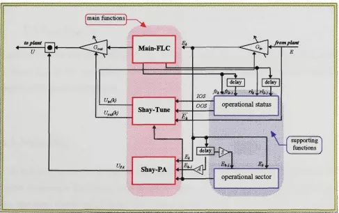
The thesis introduces a universal fuzzy logic conttoUer straeture. The stracture proposed combines three main functions and two support fimetions. The support functions are implementing novel fijzzy logic concepts developed and used in this work. These concepts represent the plant and the controller states during the operation time. The main fimetions consist of a main fiizzy logic controller refered to as Main-FLC where the initial knowledge about the system is stored. The second main function considers the phase and amplitude of the final control signal. It is called Shay-PA and it implements an implicit on-line tuning and adaptation of the Main-FLC membership functions and rales. The third mam function is called Shay-Time and is concerned with the input and output ranges of the Main-FLC. An adaptation mechanism is implemented for on-line updating of the J^in-FLC ranges. Both the support and the main functions operate in conjunction with each other. The decision meehaiusm implemented in the overall stracture is designed with the goals of robustness and reusability in mind.
LIST OF FIGURES
Figure 2.1 Figure 3.1 Figure 3.2 Figure 3.3 Figure 3.4 Figure 3.5 Figure 3.6 Figure 3.7 Figure 3.8 Figure 3.9 Figure 3.10 Figure 3.11 Figure 4.1 Figure 5.1 Figure 5.2 Figure 5.3 Figure 5.4 Figure 5.5 Figure 5.6 Figure 5.7 Figure 5.8 Figure 5.9 Figure 5.10 Figure 5.11 Figure 6.1 Figure 6.2 Figure 7.1 Figure 7.2 Figure 7.3 Figure 7.4FLC layout Page 15 power system stability analogy Page 24 power -angle curve Page 25 electrical power system stabiUty classification Page 26 input/output domains for the rale-based PSS Page 30 Hiyama' s sectors in the phase plane Page 32 gain factor dependence Page 3 3
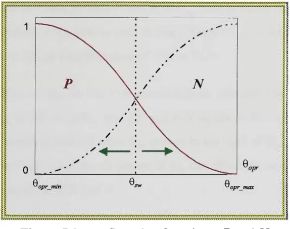
modified AO-ATO phase plane Page 34
linear P and N functions Page 34 anticipatory FLC for PSS design Page 36 input classes for the anticipatory FLC Page 37 output classes for the anticipatory FLC Page 38 Shay algorithm Page 46 second order plant Page 49 six different sectors in the unit step response of a second Page 50 order system
operational sectors, three dimensional view Page 51 operational sectors from the error signal as performance Page 52 monitor
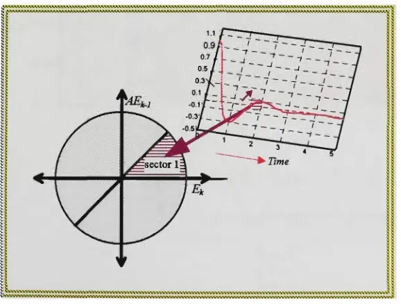
Figure 7.5 different allocations of 9^^ in sector 1 Figure 7.6 operation in sector 1
Figure 7.7 FLC used for sector 1
Figure 7.8 conttol surface for sector 1 FLC Figure 7.9 operation in sector 2
Figure 7.10 FLC used for sector 2
Figure 7.11 conttol surface for sector 2 FLC Figure 7.12 operation in sector 3
Figure 7.13 FLC used for sector 3
Figure 7.14 conttol surface for sector 3 FLC Figure 7.15 operation in sector 4
Figure 7.16 FLC used for sector 4
Figure 7.17 conttol surface for sector 4 FLC Figure 7.18 operation in sector 5
Figure 7.19 FLC used for sector 5
Figure 7.20 conttol surface for sector 5 FLC Figure 7.21 operation in sector 6
Figure 7.22 FLC used for sector 6
Figure 7.23 conttol surface for sector 6 FLC Figure 7.24 general procedures in Shay-PA
Figure 8.1 the decision ttee to select the operational modes Figure 8.2 Y, levels
Figure 8.3 updating sttategy m modes 1 and 2 Figure 8.4 input updating in modes 1 and 2 Figure 8.5 output updating in modes 1 and 2 Figure 8.6 updating sttategy in mode 3 Figure 8.7 input updating in mode 3 Figure 8.8 output updating in mode 3 Figure 8.9 overall Shay-PA operations
Figure 9.1 SALT parameters evaluation criteria
Figure 9.2 Imear third order model of a synchronous generator Figure 9.3 closed loop conttol used in the investigation study Figure 9.4 nested loops used m the investigation study
Figure 9.5 Figure 9.6 Figure 9.7 Figure 9.8 Figure 9,9 Figure 9.10 Figure 9.11 Figure 9.12 Figure 9.13 Figure 9.14 Figure 9.15 Figure 9.16 Figure 9.17 Figure 9.18 Figure 9.19 Figure 9.20 Figure 9.21 Figure 9.22 Figure 9.23 Figure 9.24 Figure 9.25 Figure 9.26 Figure 9.27 Figure 9.28 Figure 9.29 Figure 9.30 Figure 9.31 Figure 10.1 Figure 10.2 Figure 10.3 Figure 10.4 Figure 10.5 Figure 10.6
Up pattern with respect to .S* Up pattern with respect to A Pp pattern with respect to L
\ip pattern with respect to T \ip patterns
\Xn pattern with respect to S \i„ pattern with respect to A \i„ pattern with respect to L \in pattern with respect to T \in patterns
if pattern with respect to S
ty pattern with respect to A
ty pattern with respect to L tf. patterns
\eg\av pattern with respect to iS"
|e,|^ pattern with respect to A
\eg\av pattern with respect to L \e,\^ partem witii respect to T
kilov patterns
ej pattern with respect to S Cj pattern with respect to L ei pattern with respect to T ei patterns
S factor effect A factor effect L factor effect
/factor effect
torques influencing the synchronous machine P„ and Pg versus 5
variations in P^ and 5 after sudden load change P-CFLC
P-C FLC conttol surface Shay-Exciter block diagram
Figure ] Figure ] Figure ] Figure ] Figure ] Figure ] Figure ] Figure Figure Figure Figure Figure Figure Figure Figure Figure Figure Figure Figure Figure ^ Figure ] Figure ] Figure ] Figure ] Figure ] Figure ] Figure 1 Figure ] Figure I Figure 1 Figure 1 Figure 1 Figure 1 11.1 11.2 11.3 11.4 11.5 11.6 11.7 11.8 11.9 11.10 11.11 11.12 11.13 11.14 11.15 11.16 11.17 11.18 11.19 11.20 11.21 11.22 12.1 L2.2 12.3 12.4 [2.5 [2.6 2.7 2.8 2.9 2.10 2.11
general view of laboratory setup laboratory setup block diagram dc motor (prime mover)
synchronous generator (Scot 5kva) active/reactive load bank plate adjustable reactors
variable reactors circuity DPC/C40 board view DPC/C40 board layout the rectifier bridge
rectifier bridge input/output characteristics
optical shaft encoder coimected to the synchronous generator shaft
counter and D/A circuit view
^mech versus v^^ from the counter D/A circuit
counter and D/A circuit layout isolation box
field drive unit
schematic diagram of the field drive unit PC-py and DSP-Py synchronisation flowchart Shay functions flowchart
FLC drivers template FLC drivers flowchart
terminal voltage (pu), TEST-SLl
rotor angle (electtical degrees), TEST-SLl speed deviation (pu), TEST-SLl
excitation signal (volts), TEST-SLl terminal voltage (pu), TEST-SL2
rotor angle (electrical degrees), TEST-SL2 speed deviation (pu), TEST-SL2
excitation signal (volts), TEST-SL2 terminal voltage (pu), TEST-SL3
rotor angle (electrical degrees), TEST-SL3 speed deviation (pu), TEST-SL3
Figure Figure Figure Figure Figure Figure Figure Figure Figure Figure Figure Figure Figure Figure Figure Figure Figure Figure Figure Figure Figure Figure Figure Figure Figure Figure Figure Figure Figure Figure Figure Figure Figure 12.12 12.13 12.14 12.15 12.16 12.17 12.18 12.19 12.20 12.21 12.22 12.23 12.24 12.25 12.26 12.27 12.28 12.29 12.30 12.31 12.32 12.33 12.34 12.35 12.36 12.37 12.38 12.39 12.40 12.41 12.42 12.43 12.44
excitation signal (volts), TEST-SL3 terminal voltage (pu), TEST-LLl
rotor angle (electtical degrees), TEST-LLl speed deviation (pu), TEST-LLl
excitation signal (volts), TEST-LLl terminal voltage (pu), TEST-LL2
rotor angle (electrical degrees), TEST-LL2 speed deviation (pu), TEST-LL2
excitation signal (volts), TEST-LL2 terminal voltage (pu), TEST-LL3
rotor angle (electtical degrees), TEST-LL3 speed deviation (pu), TEST-LL3
excitation signal (volts), TEST-LL3 terminal voltage (pu), TEST-LL4
rotor angle (electrical degrees), TEST-LL4 speed deviation (pu), TEST-LL4
excitation signal (volts), TEST-LL4 terminal voltage (pu), TEST-VSl
rotor angle (electrical degrees), TEST-VSl speed deviation (pu), TEST-VSl
excitation signal (volts), TEST-VSl terminal voltage (pu), TEST-VS2
rotor angle (electtical degrees), TEST-VS2 speed deviation (pu), TEST-VS2
excitation signal (volts), TEST-VS2 terminal voltage (pu), TEST-VS3
rotor angle (electtical degrees), TEST-VS3 speed deviation (pu), TEST-VS3
excitation signal (volts), TEST-VS3 terminal voltage (pu), TEST-VS4
rotor angle (electrical degrees), TEST-VS4 speed deviation (pu), TEST-VS4
excitation signal (volts), TEST-VS4
Page
Page
Page ]
P ^ e ]
Page ]
Page ]
Page ]
Page ]
Page ]
P ^ e ]
Page I Page I Page 1 Page 1 Page ] Page 1 Page 1 Page 1 Page 1 Page 1 Page 1 Page 1 Page 1 Page 1 Page 1 Page 1 Page 1 Page 1 Page ] Page 1 Page I
P a g e :
Figure Figure Figure Figure Figure Figure Figure Figure Figure Figure Figure Figure Figure Figure Figure Figure Figure Figure Figure Figure Figure Figure Figure Figure Figure. Figure. Figure. 12.45 12.46 12.47 12.48 12.49 12.50 12.51 12.52 12.53 12.54 12.55 12.56 12.57 12.58 12.59 12.60 12.61 12.62 12.63 12.64 12.65 12.66 12.67 12.68 4.1 4.2 4.3 Figure ^.4
terminal voltage (pu), TEST-VLl
rotor angle (electrical degrees), TEST-VLl speed deviation (pu), TEST-VLl
excitation signal (volts), TEST-VLl terminal voltage (pu), TEST-VL2
rotor angle (electtical degrees), TEST-VL2 speed deviation (pu), TEST-VL2
excitation signal (volts), TEST-VL2 terminal voltage (pu), TEST-VL3
rotor angle (electtical degrees), TEST-VL3 speed deviation (pu), TEST-VL3
excitation signal (volts), TEST-VL3 terminal voltage (pu), TEST-VL4
rotor angle (electrical degrees), TEST-VL4 speed deviation (pu), TEST-VL4
excitation signal (volts), TEST-VL4 terminal voltage (pu), TEST-LG
rotor angle (electrical degrees), TEST-LG speed deviation (pu), TEST-LG
excitation signal (volts), TEST-LG terminal voltage (pu), TEST-LLG
rotor angle (electrical degrees), TEST-LLG speed deviation (pu), TEST-LLG
excitation signal (volts), TEST-LLG convex membership function
input^output classes
defiizzification area selected by the L/R COG L/R COG fuzzy processing
LIST OF TABLES
Table 3.1 Table 5.1 Table 5.2 Table 5.3 Table 5.4 Table 7.1 Table 8.1 Table 8.2 Table 8.3 Table 8.4 Table 8.5 Table 8.6 Table 8.7 Table 11.1 Table 12.1 Table 12.2 Table 12.3 Table 12.4 Table 12.5 Table ^.1 Table A.2 Table ^.3symmetrical rales used in the rale-based PSS
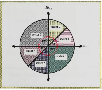
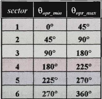
sectors division
numerical example of operational sector
rale base to derive IDS
rale base to derive OOS
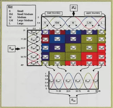
range of G^p^ for each sector
fuzzy rale base to determine the Main-FLC status
manipulating the e^s and t h e / t ^
input domain updating in modes 1 and 2
output domain updating in modes 1 and 2
input domain updating in mode 3
output domain updating in mode 3
timing and sequence in figure 8.9
synchronous generator parameters
sudden small load changes testing conditions
large load changes testing conditions
small change in reference voltage testing conditions
large change in reference voltage testing conditions
ttansmission line short circuit testing conditions
SISO system rale table
sides rale table
sides rale table for a two input one output FLC
List of Symbols
www
AI NN GA 5 Ar, Ar^ AVR PSS AGO APe ATO AQ FLC COG FM WFM L/R COG PI PID FIDE Shay ref i^P \^n set fi rl Ff Fr IV Sf \yr Sr IDS LRi LR2 LRB OOS 0 Rl 0 R2 0_Rs Gin '^ main G E,Worid Wide Web Artificial Intelligence Neural Networks Genitic Algorithms Rotor angle
Change in the synchroiusing torque Change in the damping torque Automatic Voltage Regulator Power System Stabiliser Rotor angle speed deviation Active power deviation Fhrst derivative of Ao
Actual reactive power deviation Fuzzy Logic ConttoUer
Centte Of Gravity
Fuzzy Mean defiizzification method
Weighted Fuzzy Mean defiizzification method Left/Right COG
Proportional plus Integral conttoUer
Proportional plus Integral plus Differential conttoUer Fuzzy Inference Development Environment
Stability Handling Algorithm Transient and Steady-State Reference signal
Maximum positive overshoot Maximum negative overshoot Operational sector vector
Fuzzy input mattix (fuzzification output) Fuzzy output matrix
Fired input classes flags Fired output classes flag
Degree of membership to input classes Side of fired input class
Degree of membership to output class Side for output class
Input operational status vector
Input under operation mode fiizzy value Input normal operation mode fiizzy value Input over operation mode fiizzy value Output operational status vector
Output under operation mode fiizzy value Output normal operation mode fiizzy value Output over operation mode fuzzy value Input gain
Output of the Main-FLC Output gain
'out Ui,
u
SISO VPAe.
e.
e
'opr oprjmn oprjnax L SFLG M mdl md2 mdS Fix Dec Inc S T A SALT Ufa Tj J B TB T Or P-C M H PD DSP Non-normalised E^, Input updating signal Output updating signal Final output of ShaySingle input single output FLC Shay-PA output
Operational angle The switching angle Mmimum range of Oopr Maximum range oiQ^pt Learning time
Sector flag
Total number of samples Sttengthof mode 1 Sttength of mode 2 Sttengthof mode 3 Fixing the domain range
Decrementing the domain range Increasing the domain range Sectors scale
Learning threshold Operational angle scale Shay parameters
Rise time
Absolute steady-state error Integral of error
Excitation conttol signal, field excitation Transient open loop time constant
Mechanical torque Developed inertia torque Moment of inertia
Coefficient of friction (N.m/rad/sec) Torque developed due to B
Electrical torque Damping torque Accelerating torque Rotor speed (j-ad/sec)
Mechanical speed (mech. rad/sec) Reference voltage
Terminal voltage Pre-Conttol stage Angular momentum
Normalised inertia constant Damping power
Maximum generated electrical power Digital signal processing
Direct-axis synchronous reactance
Dkect-axis ttansient reactance
x^ MIPS MOPS SRAM DPRAM DM A/D D/A
^mech
^ 0 .
PC-pp DSP-ixp
Quadrature-axis synchronous reactance Million Instractions Per Second
Million Operations Per Second Static Random Access Memory Dual-Port Random Access Memory Daughter Module
Analogue to Digital Digital to Analog
Rotor angle, mechanical degrees
Voltage output from the D/A converter Host PC driver
DSP driver
TABLE OF CONTENTS
Thesis Statement
Thesis Goals
Thesis Overview
1 Rezneiv oj Fnziy Logic Hhtorical Developtneui and
Different Ctirrent AppIiaUiojn
1.0 Inttoduction 3 1.1 Definition of Fuzzy Logic by Lotfi Zadeh as A Tool for
Representing Imprecise Information 4 1.2 Problems in the Early Days of Fuzzy Logic Development 5
1.3 Current State of Fuzzy Logic 6 1.4 Brief Review of Fuzzy Logic Applications in Different Areas 9
1.4.1 In Business and Finance 10 1.4.2 In the Medical Field 10 1.4.3 In Consumer Products 11 1.4.4 In Diagnosis Systems 11 1.4.5 In Scheduling and Process Planning 11
;r 2 Review of Fuzzy Logic Appiications In Process
Control
13
1 Revieiv of FLC Applications in Pouter System
Engineering
2.0 Inttoduction 14 2.1 Fuzzy Logic ConttoUer Stracture and Operation 14
2.1.1 Fuzzification 15 2.1.2 Fuzzy Processing 15 2.1.3 Defiizzification 16 2.2 Advanced FLC Sttiictiires 17
2.3 Analysis and Design of FLCs 18
2.4 FLC Applications 19 2.5 Fuzzy Logic Hardware 20
21
3.0 Inttoduction 22 3.1 Power System Stability Conttol Problem Description 23
3.1.1 Rotor Angle Stability 25 3.2 Conventional Methods for Stability Conttol of Power Systems 27
3.3 Power System Modeling 28 3.4 FLCs Applications in Power Systems 28
3.4.1 Non-Conttol Applications 29 3.4.2 Conttol Applications 29 3.5 Different Approaches to FLCs Design as Power System StabiUsers
(PSSs) 30 3.5.1 Rule-Based PSS 30
3.5.2 Fuzzy Logic PSS 31 3.5.3 Adaptive Fuzzy Logic PSS 35
3.7 Comments and Commitments 40
DEVELOPMENT OF THE
FUZZY LOGIC CONTROLLER
DESIGN METHODOLOGY
BASED ON A UNIVERSAL
ADAPTIVE FLC STRUCTURE
Stability Haudling .algorithm. Transient and
Steady-St ate (Shay)
42
4.0 Inttoduction 43 4.1 Brief Overview of the Proposed Shay Stracture 45
4.1.1 Main Functions 45 4.1.2 Support Functions 47
er 5 Shay Support Functions 48
5.0 Inttoduction 49 5.1 Operational Sector Concept 49
5.2 Operational Status Concept 54 5.2.1 Preliminary Discussion 55 5.2.2 FLC Ranges Evaluation Criterion 58
5.2.3 Generalised Form of the Operational Status 63
5.2.4 lUusttative Example 65
6.0 Inttoduction 70 6.1 General Overview 70
Shay Phase and Amplitude Tuner (Shay-PA)
74
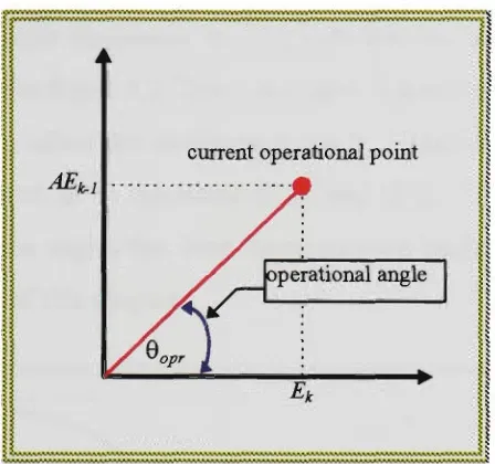
7.0 Inttoduction 75 7.1 Operational Angle Concept 75
7.1.1 Definition 75 7.1.2 Differential ConttoUer Analogy 76
7.2 Shay-PA Utilisation oftiie Operational Angle 77 7.3 Utilisation of The Operational Sector and the Operational Angle
Concepts in Shay-PA 79 7.4 Calculation of The Switching Angle 81
7.4.1 Sector 1 81 7.4.2 Sector 2 83 7.4.3 Sector 3 84 7.4.4 Sector 4 87 7.4.5 Sector 5 88 7.4.6 Sector 6 90 7.5 Derivation of CTp^ 93
8.0 Inttoduction 96 8.1 Plant Performance Considerations in Tuning 96
8.1.1 Operational Sector Information 96 8.1.1.1 Determining the Current Mode 97 8.1.2 Non-Normalised Performance Monitor Information 99
8.2 Main-FLC Performance Consideration in Tuning 100 8.3 Manipulating Main-FLC and Plant Parameters 101 8.4 Updating Sttategies for Input and Output Ranges 103
8.4.1 Modes 1 and2 103 8.4.1.1 InputDomain 103 8.4.1.2 OutputDomain 105
8.4.2.1 InputDomain 106 8.4.2.2 OutputDomain 108 8.5 Calculation of Input and Output Tuning Signals 109
8.6 Updating Input and Output Scaling Factors 110
112
Main Indicators Performance
9.0 Inttoduction 113 9.1 Evaluation Criteria 113
9.2 Evaluation Procedure 114 9.3 Domain of Sttidy 115 9.4 Criteria Patterns 117
9.4.1 Maximum Positive Overshoot Criteria 117
9.4.1.1 Effect of .S Factor 117 9.4.1.2 Effect of ^ Factor 117 9.4.1.3 Effect of Z Factor 118 9.4.1.4 Effect of TFactor 119 9.4.2 Maximum Negative Overshoot Criteria 120
9.4.2.1 Effect of ^Factor 120 9.4.2.2 Effect of ^ Factor 121 9.4.2.3 Effect of Z Factor 122 9.4.2.4 Effect of JFactor 122 9.4.3 Rise Time Criteria 124
9.4.3.1 Effect of 5'Factor 124 9.4.3.2 Effect of ^ Factor 124 9.4.3.3 Effect of Z Factor 125 9.4.3.4 Effect of ZFactor 125 9.4.4 Absolute Steady-State Error Criteria 127
9.4.5.1 Effect of ^Factor 131 9.4.5.2 Effect of ^ Factor 131 9.4.5.3 Effect of Z Factor 131 9.4.5.4 Effect of JFactor 132 9.5 Designer Guidelines for Individual Parameters Effect on
Performance Indicators 134
IMPLEMENTA TION OF A
UNIVERSAL FUZZY
CONTROLLER IN THE
EXCITA TION CONTROL
Shav in the Excitation Control
138
10.0 Inttoduction 139 10.1 Preliminary Discussion 139
10.1.1 The Swing Equation 139 10.1.2 The Equal Area Criteria 143 10.2 Conttol Sttategy and Objectives 146
10.3 Pre-Conttol Stage 149 10.3.1 Processing and Scaling of the Rotor Angle Speed
Deviation 149 10.3.2 Voltage Stability 150
10.4 Shay-Exciter 152
Hardware and Software (2'oniponents
Dei^elopment
154
11.0 Inttoduction 155 11.1 Hardware Developed and Used 156
11.1.1.2 Synchronous Generator 158
11.1.1.3 LoadBanks 159 11.1.1.4 Adjustable Reactors 159
11.1.1.5 DSP Board (TMS320C40) 160 11.1.2 Machine/Computer Interfacing Hardware 163
11.1.2.1 Rectifier Bridge 163 11.1.2.2 Optical Shaft Encoder 164 11.1.2.3 Counter and D/A Ckcuit 164
11.1.2.4 Isolation Box 167 11.1.2.5 Field Drive Unit 167 11.2 Software Development 170
11.2.1 Host Processor Driver 170 11.2.2 DSP Processor Driver 172
11.2.3 Shay Module 173 11.2.3.1 FLC Drivers 175 11.2.3.2 General Purpose Fuzzy Processing Functions 175
Laboratory Te<ls and Results 180
12.0 Inttoduction 181 12.1 Shay-Exciter Performance Tests Under Sudden Load Changes 181
12.1.1 Small Load Changes 181 12.1.1.1 TEST-SLl 182 12.1.1.2 TEST-SL2 183 12.1.1.3 TEST-SL3 185 12.1.2 Large Load Changes 187
12.1.2.1 TEST-LLl 187 12.1.2.2 TEST-LL2 189 12.1.2.3 TEST-LL3 190 12.1.2.4 TEST-LL4 192 12.2 Shay-Exciter Performance Tests Under Change in Reference
Voltage 194 12.2.1 Small Change in Reference Voltage 194
12.2.2 Large Change m Reference Voltage 200
12.2.2.1 TEST-VLl 201 12.2.2.2 TEST-VL2 202 12.2.2.3 TEST-VL3 204 12.2.2.4 TEST-VL4 205 12.3 Shay-Exciter Performance Tests Under Transmission Line Short
Cu-cuits 207 12.3.1 TEST-LG 207
12.3.2 TEST-LLG 209
MAIN RESULTS AND
CONCLUSION
13.0 Inttoduction 213 13.1 Main Results and Achievements 213
13.2 Publications and Presentations 217 13.3 Directions of Future Development 219
Main Restdis and Conclusion
>mdiK B.3 OSP-Up Driver Soyrce Code
Shay Module Source Code
lijc B.S Subfunctions Source Code
FLC Drivers Source Code
Shay (i Source Code
ipeocllx B,8 Shay rl Source Code
.9 Shay bdr Source Code
THESIS STATEMENT
Fuzzy logic conttol is a fact in modem conttol applications. Since the early days of its use the technology has attracted a ttemendous amount of attention and review. It brought to reality some old expectations m automatic conttol. Fuzzy logic provided the practical means to constract smart and intelligent conttollers. These conttoUers are able to implement the already avaUable knowledge on how to operate a system in addition to learning and developing their knowledge throughout the process. The conttoUer knowledge is developed via means of dynamic data storage of conttol rales, objectives and parameters. Moreover fiizzy logic brought to life the possibility of applying modem technology ie. computers and communication systems in a more practical way. Fuzzy logic provides the mechanism for manipulatmg uncertamty and vagueness impeded in most of real time applications.
However, the success story behind fuzzy logic was shadowed with many problems. Fuzzy logic is well stractured by the fiizzy set theory proposed by Zadeh in 1964 [1]. However, practical implementation of fuzzy logic especially in automatic conttol is not a well stractured field as yet. The design procedure of a fuzzy logic conttoUer is in most cases an add-hoc procedure. The designer's experience and trial and error attempts are the mam keys to have a working conttoUer. These design procedures made it very hard to predict and forecast the future behaviour of the conttoUer. Evaluation of the designed conttoUer prior to implementation is not possible under this design procedure.
The two conttasts which were the main motivation for this thesis are as foUows: 1) The applicability of fiizzy logic in almost every aspect of our lives and what it brings of future anticipation and 2) the lack of stractured methodology, design procedures and evaluation tools resulting in uncertainty and arguments against fuzzy logic.
To be able to enjoy the fraits of fiizzy logic a stractured design methodology is requned. This methodology should give the designer the upper hand in setting the conttoUer's objectives and not to leave the conttoUer performance subject to random choices of parameters.
THESIS GOALS
The main goal of this thesis is to develop a universal fuz^ logic controller design
methodology and to test its applicability in real life applications.
To achieve the main goal of the thesis the following sub-goals and objectives were defined:
1) Develop Methods of Improving the Knowledge Representation in FLC
This goal deals with the development of ways to utilise and refine the real time inputs to the conttoUer. The objective is to provide a better representation of the system state that enhances further processing and conttol.
2) Develop and Improve Fuzzy Reasoning
This goal is concerned with the processing of fiizzy rales which serves as a base for any FLC operation. It aims to improve the performance of the reasoning mechanism in the FLC. The optimum use of the already available knowledge to the FLC is the objective of this goal.
3) Develop a Structured On-Line FLC Parameter Tuning Procedure
This is one of this thesis's main goals. The main objective here is to develop a method of an automatic adaptation to plant and/or environment changes. The designer should not need to rebuild the FLC due to changes in its operational environment. The timing mechanism should be simple in use and fast in operation.
4) Develop a Universal FLC Structure
for different applications and it should encapsulate all the objectives of the thesis. The developed uruversal FLC stracture should have the minimum possible number of variables that require alterations when the stracture is used in different applications.
5) Develop the Tools of Parameter Tuning and Evaluation of their Influence on the Performance Indicator
The uruversal FLC stracture should be equipped with tools and parameters that are accessible by the designer. These tools should aUow the designer to inttoduce changes in the FLC design. The change should have a clear effect on the conttoUer performance according to some predefined criteria. This goal is set in order to give the designer a better view of the proposed FLC performance prior to the implementation and an ability to evaluate different design ideas.
6) Develop an Evaluation Criteria of the Controller Performance
This goal emerged as a major goal while mvestigating goal 3. The questions of when, what and how to tune were raised and an answer was set as the goal of defining measurable values used to enhance the tuning process.
7) Develop Practical Guidelines for FLC Design
This goal aims at providing practical guidelines for using the universal FLC developed in the thesis (see goal 4) in different conttol applications. There should be clear directions of how and where to use it as well as what the designer should do to use it in different cases.
8) Prove the Applicability and Effectiveness of the Proposed Methodology in Real Time Applications
The objective of this goal is to prove the appUcability of the intended universal FLC stracture in real industrial applications. To achieve this the proposed methodology should be comprehensively tested by simulation and phototyping and by the design of a real conttol system implementing
this methodology.
10) Develop an FLC System for the Stability Control of Electrical Power Generator
This goal was derived from goal 9. A classical and very important application chosen was the excitation conttol of a synchronous generator connected to an infmite bus through a ttansmission line. A fully fiizzy logic based excitation system is to be built based on the universal FLC stracture in goal 4. This goal was set to prove that the intended universal FLC stracture is able to replace classical FLCs and conventional
conttollers in standard and advanced applications. This is to be proven by replacing the power system stabiliser and the automatic voltage regulator in the excitation conttol loop with one single conttoUer.
11) Develop Methods and Means for Practical Implementation of the Universal FLC Structure Proposed
General purpose software and conttol protocols are needed to achieve this goal. This software and firmware system will allow implementing the FLC developed in the thesis. The practical implementation should be performed via generalised software and conttol protocols. These programs and protocols should be applicable to different envu-oiunents.
THESIS OVERVIEW
The thesis consists of four main sections with a total of 14 chapters and includes 10 appendices. The division of the sections and chapters is based on a logical flow starting with a general analysis of the current situation in FLC design and extending towards the development of a methodology for FLC design, description of a universal FLC stracture, its analysis and research, then an implementation and design of the FLC system for the excitation conttol of electric power generation is presented.
Section 1: Analytical Review of Fuzzy Logic Methodologies and
Applications
An analytical review of fuzzy logic conttol methods based on the literature survey is provided in this section. The early days as well as the fundamentals of fuzzy logic are presented in chapter 1. The chapter gives a brief description of the current status of fiizzy logic and its areas of application.
Fuzzy logic in process conttol is mttoduced in chapter 2. A survey on fiizzy processing, simple and advanced FLC stractures, FLC stability and fuzzy hardware is included in the chapter. Chapter 3 reviews the appUcation of fiizzy logic in power systems with the emphasis on its applications in the excitation conttol.
Section 2: Development of the Fuzzy Logic Controller Design
Methodology Based on Universal Adaptive FLC Structure
This section inttoduces the proposed universal FLC stracture. Chapter 4 gives an overview of the stracture which is called Stability handling Algorithm,
ttansient and steady-state (Shay). The stracture comprises three mam fimetions and two support functions.
Chapter 5 describes the support functions where the innovative concepts of
measuring the plant and the FLC status are inttodueed. Shay main fimetions are inttodueed in chapters 6,7 and 8. Chapter 6 inttoduces the Main-FLC which is one of the main Shay fimetions. Shay-PA which is the second main fiinction in Shay is presented in chapter 7. Shay-PA is responsible for the implicit updating and tuning of the Main-FLC classes and rales. The operational angle concept and its analogy to the proportional plus differential conttoUer algorithm is presented m chapter 7. Chapter 8 inttoduces Shay-Tune which is the third main function in Shay. Shay-Shay-Tune is responsible for the updating and tuning of the input and output ranges of the Main-FLC. The relationship between the main and support functions is clearly defmed and explained along with the description of the main functions operations.
Chapter 9 provides the complete evaluation and design considerations based
on pre-defmed performance criteria. The chapter explains with the aid of examples obtained by computer simulations the effect of each of the designer free variables included in Shay on the system performance.
Section 3: Implementation of A Universal Fuzzy Controller in the
Excitation Control
The practical implementation of Shay-FLC is explamed in this section.
Chapter 10 explains, in detail, the knowledge engineering techniques used to
Chapter 11 describes m detail the hardware developed and used for the
practical implementation of the Shay-FLC in the excitation conttol. The software developed and applied for the practical implementation is also inttodueed in chapter 11. Chapter 12 presents the laboratory tests and cases studied along with the real time implementation results.
Section 4: Main Results and Conclusion
The conclusion, project achievements, publications and future work directions are presented in this section.
ANAL YTICAL REVIEW
OF FUZZY LOGIC
METHODOLOGIES AND
APPLICA TIONS
Review of Fuzzy Logic Historical
Development and Different
Curren t Applicatio ns
Review of Fuzzy Logic
Applications in Process Control
[evtew
Development and,
Current AppUcations
^l^.^nA".^^^^^s^AnA.^V^V
1.0
LI
1.2
1.3
1.4
1
1
1
1
1
1
Introduction
Definition of Fuzzy Logic by Lotfi Zadeh as A Tool for
Representing Imprecise Information
Problems in the Early Days of Fuzzy Logic Development
Current State of Fuzzy Logic
Brief Review of Fuzzy Logic Applications in Different
Areas
,4.1 In Business and Finance
,4.2 In the Medical Field
,4.3 In Consumer Products
,4.4 In Diagnosis Systems
Chapter 1: Review of Fuzzy Logic Methodologies and Applications Page 3
1.0 INTRODUCTION
Fuzzy logic is becoming one of the main stteams in today's research bibUography. There
is an ocean of references and resources explaining or dealing with the topic. The IEEE
pubUshed over 2,266 conference and joumal papers related to fuzzy logic in one way or
another between the years 1990-1996. The keyword fuzzy logic results in over 13,000
sites in the Internet, which can be easily seen as the only competitor to fiizzy logic m the
speed of popularity amongst technical issues this decade. This alone is an enough reason
for research to commence in this area. However, one has to ask why? And how this term
"fuzzy" became of such great importance and popularity so quickly?.
Fuzzy logic existed along time ago, even before Zadeh's first paper in 1965 [1] when he
defmed the famous ''fuzzy sef\ This is not meant to dishonour Professor Lotfi Zadeh from
his novelty. It is just surprising, that it took the human mind so long to realise the existence
of such an idea, which is one of the main essence of human life on this planet. On the
conttary, around 300 B.C. Aristotles, the famous Greek philosopher, stated that " every
thing either to be or not to be". It was this very basic idea where the binary system (the 0
and 1 logic) came from. Things are either trae or false. It is very hard to draw a clear line
between elderly and youth. Is it trae that a man at 60 year of age is old? Can we draw a
clear border line here? And if so, what classification does a 59 year old man have? Or do
we need to consider the age of retirement to be fiizzy? Considering health and ability to
work as a measure? If this is trae, we may classify a healthy 60 year old man as young and
an ill 25 year old man as old.
A general overview of fuzzy logic is provided in this chapter. The chapter describes the
very basic concepts of fiizzy logic. Followed by the early days of opposition to the fiizzy
logic idea and the current status of the technology. Description of different domains where
fiizzy logic is currentiy being used concludes the chapter.
Chajjpter 1: Review of Fuzzy Logic Methodologies and j^pttcations Page 4
1.1 DEFINITION OF FUZZY LOGIC BY Lotfi Zadeh
AS A TOOL FOR REPRESENTING IMPRECISE
Lotfil Zadeh, the father of fiizzy logic, came up with the idea of graded sets and labeUed it as th(? fiizzy sets in 1965 [1]. In this paper, Zadeh wrote
i
' " Afuzxy set is a class of objects with a continuum of grades of membership.
^Such a set is characterised by a membership (characteristic) function which
^assigns to each object a grade of membership ranging between zero and
one*'.
The paper defined and formulated the basis of fuzzy logic. The most important definition
i
was C|>f the fuzzy set in the form of
^ A fiizxy set (class) A in X is characterised by a membership function (fA(x))
which associates with each point inXa real number in the interval [0,1 J with
the value (fA(x)) atx representing the "grade of membership" ofXin A.
The piaper went into deeper defmitions and operations related to the fiizzy sets, among which^ one can mention are:
Empty fuzzy set
A fiizzy set is empty if and only if its membership fimction is identically zero.
Equality between two fuzzy sets
Two fuzzy sets A and B are equal, A=B, if and only ^fA(^)=fB(^) for all x'mX.
The complement of a fuzzy set
The complement of a fiizzy set A (denoted A")
i&fA=l-fA-Containment of a set into another set
A is contained in B (or equivalentiy, ^ is a subset of .B or ^4 is smaller than or
^/B)-Chapter 1: Review of Fuzzy Logic Methodologies and Applications Page 5
Union of two fuzzy sets
The union of two fiizzy sets A and B with membership functions ^(^xj and^^xj respectively is a fuzzy set C (written as C-A u B) whose membership function is related to those of ^ and B hyfc(x)=max[fA(x) , f^(x) ],x &X.
Intersection of two fuzzy sets
The intersection of two fiizzy sets A and B with respective membership functions fA(x) and fB(x) is a fuzzy set C written as C=A n B whose membership function is related to those of ^ and B hy fc(x)=min[fA(x) , fs(x) ],
x&X.
Zadeh described the use of some algebraic operations on fiizzy sets. These operations can be derived as the corresponding algebraic operations on the corresponding membership functions. Zadeh explamed the fuzzy interpolation of these algebraic operations;
Algebraic product of ^4 and B (AB):fAs
=fAfB-Algebraic sum of.4 and B (A+B):fA+B ^fA^fB-fA-fs
Absolute difference between A and B (\A-E{ ):f\a.h\ ^ IfA-fal •
Some other basic concepts and definitions where included in the paper. This paper laid down the foimdations for all the fiizzy logic oriented research. Later on in 1973, Zadeh refined these concepts in his other paper [2] in which a vision of where this newly defmed prior existing concept is applicable.
1.2 PROBLEMS IN THE EARLY DAYS OF FUZZY
LOGIC DEVELOPMENT
Chapter 1: Review of Fuzzy Logic Methodologies and Applications Page 6
successfully implemented fiizzy logic towards hiding this fact for commercial reasons. Two good examples in this sense are given by Elkan [3] when he described the talk by Takeo Kanade in irCAI'91 about Matsushita's camcorder image stabUiser system without mentioning its use of fuzzy logic. The second example was the 1994 Honda Accord automatic ttansmission with an embedded fijzzy logic conttoUer and how it was advertised as a " grade logic" conttoUer.
1.3 CURRENT STATE OF FUZZY LOGIC
We beUeve that this kind of tough fuzzy logic childhood was useful for the idea to get sttonger as it reaches its mature years. The opposition the idea had proved to be trae motivating factor for the trae believers in the fuzzy principle. They successfiiUy devoted a ttemendous amount of effort in explaining and exploring the superiority of this idea, and to demonstrate its applicability in many aspects of our life.
Zadeh, as expected, played a great role in this contest. He carefiiUy tried to prove that fiizzy logic is closer to the human way of thinking and reasoning than Boolean logic. In his paper titied "Fuzzy Logic = Computing With Words" published in 1996 [4] he stated that:
''the main contribution of fuzzy logic is a methodology for conqfuting with words".
Others tried to follow a similar path in provmg that it is more 'human like' to reason in the form of IF-THEN rales that have more states than the Aristotles two states logic. Kosko in his book "Fuzzy Thinking' [5] compared the eastern culture with its spiritual values and people's ways of thinking to the western one. He came up with the conclusion that the cultural barriers, especially m the scientific circles, were the mam reasons why the western circles rejected the idea at first and why the eastem people were those who promoted it. Mamdani [6] reached a similar conclusion.
Chapter 1: Review of Fuzzy Logic Methodologies and AppUcations Page 7
In addition to that the first evidence of its appUcabiUty in real life was established in England by Mamdani hi 1975 [7].
The picture is much different in the late nineties. Fuzzy logic became a legacy. Westem institutes and researchers are doing their best to pick up some of what they have already lost in the field. The west is sttongly promoting fuzzy logic. In fact, some people seems to be marketing it m such a way that facts are mixed with expectations and limitations or problems are ignored. This is creating a "fiizzy" idea about fuzzy logic in peoples minds. Fuzzy logic is shown as the ultimate solution and as a replacement for other techniques. One of those fiizzy logic promoters is Earl Cox. In his World Wide Web (WWW) article titled "The Seven Noble Truths of Fuzzy Logic" [8] he highlighted some very important issues about fuzzy logic, some of them are trae and others fall in the new exaggerating ttend in fiizzy literature. Cox "Noble Traths" are presented and discussed in this section because they represent most of what is being propagated about fiizzy logic. These traths can be considered as a good frame for a brief description of the current fiizzy logic state.
Truth One: "There is nothing fuzzy about fuzzy logic" [8]
This is a very solid trath and it is important to emphasise this fact. The name "fiizzy" was unfortunately misunderstood by many people. The claims that fiizzy logic violates the solid proven laws or that fuzzy logic produces a vague, or uncertain result are, until now, appearing here or there. Another WWW article [9] gave good support for this trath by stating that " fuz^ logic is not
about thinking in a fuzzy, ie. Imprecise way, as its opponents would have us
to believe, instead, fuzzy logic is about precise thinking about imprecise
things".
Truth Two: "Fuzzy logic is different from probability" [8]
Chapter 1: Review of Fuzzy Logic Methodologies and Applications Page 8
important to publicise, as the relationship between fuzzy logic and the probability theorem is stUl not very clear for many people.
Truth Three: "Designing the fuzzy set is very eas^' [8]
This is not fully accurate in practical terms. It is trae that the realisation of the problem is much easier using fuzzy sets as it is closer to the human way of thinking. However when it comes to having a working system based on fuzzy logic it needs more than just simple sketching of the problem. The defined fuzzy domains and subdomains have to be tuned to match the problem status and the required solution.
Truth Four: " Fuzzy systems are stable, easy tuned and can be conventionally
validated " [8]
The stabUity, tuning and validation of a fuzzy system is not a settled matter yet. However, in process conttol, people tend to argue the stability as industrial and behaviour requirements and not on means of mapping with conventional techniques. Sugeno and his colleagues [10] provided a good overview for this issue. This fourth trath by Cox is one of marketing statements fiizzy logic promoters are using. However, such claims when not supported with evaluation and validation tools can have negative impact on fuzzy logic progress as a branch of artificial intelligence (AI) and conttol.
Truth Five: " Fuzzy systems are different from and complementary to neural
networks" [8]
Chapter 1: Review of Fuzzy Logic Methodologies and Applications Page 9
Truth six: "Fuzzy logic "ain't" just process control any more" [8]
This can be one of the most powerfiil points in favour of fiizzy logic. The technique emerged as the solution in many different fields that were almost impossible to be computerised based on the very old Aristotles principle. Refer to section 1.4 in this chapter for various applications of fuzzy logic.
Truth seven: "Fuzzy logic is a representation arui reasoning process" [8]
Fuzzy logic provided the means to represent and model different environments in a non precise manner, while still conserving the characteristics of the particular environment. It provides this representation so that non-determiiustic parameters can be processed in a fuzzy reasoning process that mimics the human reasoning.
1.4 BRIEF REVIEW OF FUZZY LOGIC
APPLICATIONS IN DIFFERENT AREAS
Apart from these theoretical and philosophical arguments, fiizzy logic reached its adulthood m practical terms. It is very hard to fmd any new concept that was widely adopted in many fields of our modem life as quickly as fiizzy logic did. In fact the concept reached much beyond the expectations, and it became a legacy and a good marketing tool to label consumer's goods with "fuzzy logic inside". Sugeno published a book [11] on fuzzy applications and the literature is full of references to many other applications that appear every day.
The most popular field of fuzzy logic appUcations is in process conttol, where new dimensions became feasible for conttol engineers in such a way that the crowned analytical linear conttol theory is in danger of loosing its crown.
Chapter 1: Review ofFuz^; Logic Methodologies and AppUcations Page 10
technologies. Different fields of fiizzy logic appUcations are briefly presented in this section.
1.4.1 In Business and Finance
Brabazon [12] m his 1996 paper, discussed the advantages of using fuzzy logic in business computer systems. Another description of fuzzy logic emerging in the financial and business area is presented by Attaran [13] where he described the importance of fuzzy logic in removing vagueness by recognising infinite graduation between clear cut exttemes. More exploration of the power of fuzzy logic in the field is presented by Roger [14].
Business and financial appUcations of fuzzy logic involve estimation [15-17], marketing [18], scheduling [19-22], diagnosis [23] and analysis [24,25].
Other financial and business applications of fuzzy logic include insurance rate changes [26], credit card costumes forecasting [27], manufacturing, planning and decision making [28-31], risk assessment [32] and production activity control [33].
1.4.2 In the Medical Field
The very conservative medical field applied fiizzy logic in many areas. Cabello, et al. [34] used fiizzy clustering algorithms for a statistical characterisation of ECG (electtocardiogram) records. The membership function matrix of the prototype of each of the clusters, and the mattices that induce the norms in their environment give usefiil description over the ttaining set for constracting a feasible classifier for detecting ventricular arrhythmia's. Boimds et al. [35] compared the performance of a multUayer perceptton
Chapter 1: Review of Fuzzy Logic Methodologies and AppUcations Page 11
1.4.3 In Consumer Products
In his 1996 paper, Berardinis [37] gave a vision of how consumer products wiU behave in a few years time. He also described how computer and communication technologies will migrate from the domain of high standard applications to simple home appliances aUowing gas valves to communicate with gas companies and service centtes. This might be very optimistic, but looking at the currently avaUable smart dishwashers, video cameras, VCR's, microwave ovens, there is the feeling that this might happen one day, "soon". Nowadays there is even a fuzzy cooktop conttoUer on the market [38].
Fuzzy logic is also used in some heavy duty applications. For example the automatic ttain operation system in Sendi municipal subway in Japan. This system is based on a predictive fiizzy conttol [39]. Also the rale-based fiizzy logic conttoUer used to conttol the 5 MW Massachusetts Institute of Technology research reactor [40]. A fuzzy logic approach was also used in Brazil for oU recovery [41].
1.4.4 In Diagnosis Systems
The capability of the fuzzy logic principle to manipulate and deal with imprecise data in a similar fashion as a human expert gave it the boost as a great tool used in diagnosis systems. Fuzzy fault diagnosis systems have been used in [42-44]. Different fuzzy diagnosis algorithms have been described in [45,46].
1.4.5 In Scheduling and Process Planning
Chapter 1: Review of Fuzzy Logic Methodologies and Applications Page 12
1.4.6 In Expert Systems
Review of Fuzzy Logic
^rocess Co
2.0 Introduction
2.1 Fuzzy Logic Controller Structure and Operation
2.1.1 Fuzzification
2.1.2 Fuzzy Processing
2.1.3 Defuzzification
2.2 Advanced FLC Structures
2.3 Analysis and Design of FLCs
2.4 FLC AppUcations
Chapter 2: Review of Fuzzy Logic Applications in Process Control Page 14
2.0 INTRODUCTION
"It was Zadeh's paper [1]published at that time which persuaded us to use a
fiizzy rule based approach. Between reading and understanding Zadeh's
paper and having a working controller took a mere week and it was
"surprising" how easy it was to design a rule-based controller" [61.
These were the words of the first man who ever applied fiizzy logic in real time conttol applications. Mamdani published a paper about the first known fuzzy conttol application in
1975 [7]. He described his intelligent conttoUer or as he recently has preferred calling it
"non-anatyticaF conttoUer, on a laboratory prototype steam engine during his doctoral
research at Queen Mary college in the UK.
The surprising simplicity, as mentioned above, in having a working fuzzy logic conttoUer (FLC) had a negative impact on the technology in its early days. Fuzzy logic conttoUers (FLCs) did not seem to be a realistic solution in the predominant analytical conttol theory circles. Questions have been raised on the FLC stabiUty and evaluation methods.
A review of FLCs is given in this chapter with more emphasis on what is still required to be investigated. It is not scientific to go into exaggerated arguments in favour or against
FLCs. The fact is that FLCs are there and are being used in many applications.
2.1 FUZZY LOGIC CONTROLLER STRUCTURE
AIVD OPERATION
A very general definition which encompasses the majority of FLC systems may be formulated as follows:
"A FLC is a system which enhances the performance, reliability, and
robustness of control by incorporating knowledge which cannot be
accommodated in the analytical model upon which the design of a control
algorithm is based, and that is usually taken care of by manual modes of
Chapter 2: Review of Fuzzy Logic Applications in Process Control Page 15
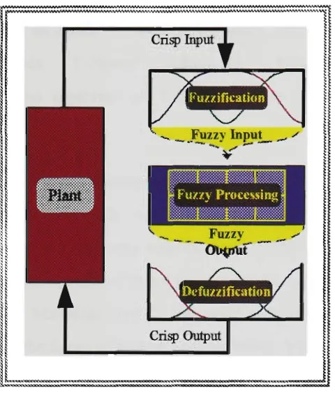
The general architecture of an FLC usually consists of three main parts as shown in figure 2.1, ie. fuzzification, fuzzy processing, and defuzzification.
Figure 2.1 FLC layout
2.1.1 Fuzzification
In this phase, the crisp input to the conttoUer is converted into a fuzzy value, symbolic representation. Grenerally, inputs to the FLC are non-fiizzy in nature, but the data manipulation in a FLC is based on the fuzzy sets theory. Hence, fuzzification of the input is necessary. To ttansform non-fuzzy (crisp) inputs into fuzzy inputs, membership functions must first be determined. Once membership functions are assigned, fuzzification takes a real input value and compares it with the stored membership function information to produce a fuzzy input value.
2.1.2 Fuzzy Processing
Chapter 2: Review of Fuzzy Logic AppUcations in Process Control Page 16
knowledge stored as a set of rales. To express knowledge by means of fiizzy rales one needs logical connectives. The most used logical connectives m standard fuzzy conttoUers are : AND and THEN [60,61]. For unplementation of the operators, the so called Norm is appUed. Some examples of the T-Norm are: Zadeh T-T-Norm; Mn(a,b), Lukasiewicz T-T-Norm
Max(a+b-1,0), and algebraic ab T-Norm (derived from the probabUity
theory) [62-64].
Although many inference methods and approaches are reported m the literature, the most frequently used inference methods are: Mamdani (symbolic) type of rales that were implemented in the first applications of fiizzy conttol. The consequence of this type of rales are symboUc, ie. conttoUer output is large. The Mamdani type of inference produces a fuzzy conttoUer output as a result of the fuzzy inference process, which has to be defiizzified to obtain a numerical conttoUer output. The other type of fiizzy rales is the Sugeno type rale [65] where the consequence of a fiizzy rale is a function (usuaUy linear) of the conttoUer inputs. Successfiil use of this type of rales in the conttol of a model car was reported by Sugeno [66,67].
2.1.3 Defuzzification
This last step is the reverse of the fuzzification operation. The fuzzy output from the rale base is ttansformed into a crisp value, realisable by the plant or system under conttol. This is done by dividing the output universe of discourse into several intersecting areas (membership fimetions).
Chapter 2: Review ofFuz^ Logic Applications in Process Control Page 17
This research resulted (in addition to the main results in sections 2 and 3) in the development of a new reasoning method referred to as L/R COG (Left/Right COG) see [73] and appendk^.
Choosing the wrong defuzzification method can adversely affect the results achieved by the inference of fuzzy rales. It appears that applying a specific defiizzification method can also affect the characteristics of a fuzzy conttoUer. For example, using the Weighted Fuzzy Mean (WFM) method ttansforms a Mamdani type conttoUer to a Sugeno type [68,69,74]. Speed and accuracy are the most important criteria for vaUdating any defiizzification techtuque applied.
2.2
A D V A N C E DFLC STRUCTURES
Recently, the designers of FLCs started using more complicated stractures of FLC to enhance and improve the performance of the conttoUers. One of these advanced stractures is the adaptive FLC stracture, where some of the conttoUer parameters are altered and modified throughout the process. The parameters that can be altered are:
1) scaling factors for both mputs and outputs of the FLC,
2) membership functions representing the meaning of linguistic values,
3) the rales set.
Chapter 2: Review of Fuzzy Logic Applications in Process Control Page 18
Hierarchical schemes are also used in recent FLCs [87,88], where the conttoUer has a stracture which changes continuously according to the input signal levels. A hierarchal stracture can have fast and sttong conttol sttategy imder large performance degrading, and a slow and smooth conttol sttategy under steady-state conditions. This scheme improves the system's robustness, and makes it less sensitive to external or internal disturbances. A comparison between adaptive and hierarchical schemes is given in [89].
2.3
ANALYSIS ANDDESIGN OF FLCs
The design of a FLC is a very "fuzzy" issue. It is hard to fmd a well stractured design methodology that the designer can follow and stiU meet the requirements of the design,
one of this thesis commitments and contributions is the development of a FLC design
methodology (see section 2). There are already many attempts in this path, however, most
of them are either recommendations or insufficient enough to be considered as a general FLC design methodology.
In [90] Kim and Yun, described the use of Genetic Algorithms (GA) in the design of proportional plus integral (Pl-like) FLC, where the conttoUer design space is coded in base-7 strings (chromosomes). Each gene matches one of 7 discrete fiizzy values. Another GA based design has been presented [91]. Input and output mapping factors are also used m the design [92].
The big-bang design, is another style in FLC design and the most popular one. As presented m many papers, this approach is based on the designer's experience and own observations. An overview of this style is given in [93]. Some recommendations on the choice of the FLC parameters are given in [94].
Chapter 2: Review of Fuzzy Logic Applications in Process Control Page 19
However, the best stabiUty requirement and security is the "performance stability" defmed by Mamdani in [6] as the "industrial requirements and the set of rules that enccpsulate a
stability requirement following the logical approach". This thesis presents a stability tool
that is based not only on a philosophical approach but on realising continuous
monitoring of the controller and the plant performance, (see section 2 for details).
2.4 FLC APPLICATIONS
From a practical point of view, one can distinguish between two major classes of FLCs for closed loop conttol:
1) a class where the FLC is involved in the supervision of the closed loop operation, thus completing and extending the conventional conttol algorithm,
2) a class where the FLC directly reaUses the closed loop operation, thus completely replacing the conventional conttol algorithm [59].
Both types of FLCs were implemented in the conttol of linear and non-linear systems. The FLC, with a particular choice of membership functions, logical operators and inputs/outputs scales, can emulate a linear conttoUer. From this point of view linear
control can be seen as a subset of fuzzy control. The best known linear conttollers are the
proportional plus integral plus differential (PID) conttollers. PID-like FLCs were implemented and demonsttated a significant performance improvement over conventional PID conttollers [98-100]. The conttol signal generated from a PID-like FLC is not an optimal average for the whole input space as in the case with conventional PID conttollers, but an interpolation between more local optimal averages.
Chapter 2: Review of Fuzzy Logic Applications in Process Control Page 20
2.5 FUZZY LOGIC HARDWARE
WITH fast growth of fuzzy logic applications in real time conttol there emerged the need for fast fuzzy processing tools. Two types of fuzzy hardware are available nowadays in the market. The first is the digital hardware with the first processors inttodueed by Togai Infralogic. The second type of fuzzy hardware is the analog type. Digital processors are performing very well in many fields. However, the digitisation process and the conversion on the other side of the output are consuming large amounts of processor time and power, this is why the analog type is becoming more feasible for fiiture growth. Analog CMOS fiizzy hardware is presented in [110], fuzzy implementations on PLAs, FPGAs, VHDL and VLSI are reported [111-115].
''Vie'.
iver System tngtneering
3.0 Introduction
3.1 Power System Stability Control Problem Description
3.1.1 Rotor Angle Stability
3.2 Conventional Methods for StabiUty Control of Power
Systems
3.3 Power System Modeling
3.4 FLCs Applications in Power Systems
3.4.1 Non-Control Applications
3.4.2 Control AppUcations
3.5 Different Approaches to FLCs Design as Power System
Stabilisers (PSSs)
3.5.1 Rule-Based PSS
3.5.2 Fuzzy Logic PSS
3.5.3 Adaptive Fuzzy Logic PSS
3.6 FLCs Design for the Excitation System
Chapter 3: Review of FLC AppUcations in Power System Engineering Page 22
3.0 INTRODUCTION
Highly integrated power networks were the solution to resolve cost efficiency and natural resources distribution problems faced by electrical power utUities since the early days of power system generation for domestic consumption\ However, as these large networks evolved, new problems and considerations for conttol engineers to maintain the operational requurements of the system emerged.
The electrical power system is highly nonlinear m nature, moreover the system parameters are largely influenced by the operational conditions which combines both generation and distribution. Load variations, faults and other disturbances (can alter the generation unit mode severely) are likely to happen quite often.
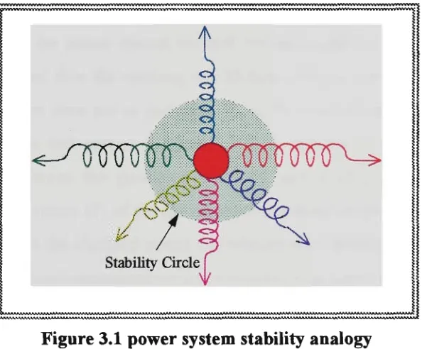
Voltage stability and synchronism are the two main problems that should be attended to when dealmg with the problem of power system conttol. Voltage stability is the abUity of the system to maintain the terminal voltage of the generator and different busses in the system within certain limits during steady-state conditions. Plus the ability to regain these margins after subjecting the system to any perturbation. Synchronism or rotor angle stability is the ability of the system to maintain synchrorusm between its rotating components. Both phenomena are linked in one way or another, which adds more complications to the conttol problem.
Power generation is a mean of energy conversion from mechanical power provided by the prime mover mto electrical power by the generator. Altering the mechanical parameters in order to meet different load demands is not the optimal solution in the short term consideration. This is due to the large time constants of the mechanical components of the system. Excitation conttol is seen as the solution for the short term stability problem. It is known that large conttol effect can be implemented in a very short time period using small amount of conttol action through conttoUing the field of the synchronous generator. The excitation system generally consists of an automatic voltage regulator (AVR) and power system stabiliser (PSS).