Copyright to IJIRSET www.ijirset.com 2748
Empirical relations to predict the probable
percentage of reduction in root fillet stress in
spur gear with circular stress relief feature
Prof Vijaykumar Chalwa1, Mr.Nagesh Kamanna2, Asst Prof Prasad Nayak3
Dean of R&D, Prof. Department of Mechanical Engineering, SMSMPITR, Akluj, Maharashtra, India1
Mechanical Engineer, Safran Engineering Services,Bangalore, India2
Asst prof,Department of Mechanical Engineering, Basava Academy,Bangalore,India3
Abstract: This work presents the possibilities of percentage of reduction in the root fillet stress of spur gear by introducing circular stress relieving feature of various sizes at different locations. Two categories of systematic analyses are carried out using finite element model of spur gear. In the first category of analyses emphasize is given to determine the maximum root fillet stress which is required as reference to determine the stress reduction factor. In addition to this, the effect of number of teeth, pressure angle, and basic parameters of rack cutter on root fillet stress is investigated. In second category which is the prime focus of this work; the effect of introducing geometric stress relief feature is carried out. Circular stress relief feature of different size at strategic locations on a spur gear tooth are introduced. This reduces the root fillet stress. The magnitude of the load shared by a gear tooth depends on the position of the point of contact of teeth engagement along the line of action. It also depends on contact ratio. High contact ratio gear teeth pairs are subjected low load in comparison low contact ratio gear for transmitting same amount of torque. A tooth is released from the load as soon as it disengages with the mating gear tooth and it is taken by the next conjugate tooth. Therefore the gear teeth are subjected varying (fatigue) load. If a gear fails by bending fatigue, the failure is catastrophic and occurs with little or no warnings. The maximum root fillet tensile stress is one of the key factors which determine the fatigue life of the gear. Therefore the magnitude of the maximum value of the root fillet tensile stress can be treated as the index of fatigue life of gear. Even slight reduction in root fillet stress leads to a large increase in fatigue life of the gears designed for the stress level above endurance limit. This type of design consideration is very common, where safety and light weight are the principal design criteria. Therefore for all the reasons cited above, this work is of more practical importance.
The program is coded in ANSYS Parametric Design Language (APDL). It automates the task of creation of model, meshing, applying boundary conditions, choosing the appropriate density of the mesh depending on the stress gradient. It also provides a means for defining the diameter and location of the circular stress relief features.
Keywords: Spur gear, nomenclature of gear, FEM etc.
I. INTRODUCTION 1.1 Overview
Copyright to IJIRSET www.ijirset.com 2749 The gear geometry required for Finite Element Analysis (FEA) can be created in any CAD software but due to geometric data loss and necessity of the transfer of geometric data from other modeling environment the geometric tooth profile is created in Ansys environment using APDL.
1.2 Classifications of gears
Generally gears are categorized into three distinct types based on relative positions of axes of shafts: 1. The transmission of power and motion between the parallel shafts. Ex: Spur and Helical gears.
2. The transmission of power and motion between those shafts whose axes are intersecting and angle between them is 90°. Ex: Bevel and Spiral bevel gears
3. The transmission of power and motion between those shafts which neither parallel nor intersecting the angle between axes is 90° but they are in different planes. Ex: Worm and Worm wheel, Crossed helical gears, Hypoid gears.
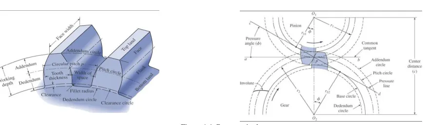
1.3 Gear terminology
Figure 1.1 Gear terminology
Addendum: -is the height by which a tooth projectsbeyond the pitch circle or pitch line.
Dedendum: -is the depth of a tooth space below the pitch line. It is normally greater than the addendum of the mating gear to provide clearance.
Base Diameter: -is the diameter of the base cylinder from which the involute portion of a tooth profile is generated.
Circular pitch: -is the arc length along the pitch circle circumference measured from a point on one tooth to the same point on the next which defines the tooth size.
1.4 Objective of the Present work
The principal objective of the work is to establish an empirical relation for spur gear to predict the root fillet stress induced in the gear geometry by introducing the stress relieving features at the stressed zone. The load is applied at Highest Point of single Tooth Contact (HPSTC). This is accomplished by the following sequential objectives:
The prime objective of the present work is to establish empirical relations to predict the percentage of reduction in root fillet stress in spur gear by introducing circular stress relief feature.
To develop an efficient and reliable program in ANSYS Parametric Design Language (APDL) to automate the process of finite element analyses. The data obtained by these analyses is used to establishing the empirical relations specified above.
1.5 Scope of the present work
Copyright to IJIRSET www.ijirset.com 2750
Material (steel): Modulus of Elasticity =2.1x10⁵ N/mm², Poisson’s ratio=0.28. Here an analysis is carried out in ANSYS environment using APD Language by considering the list of parameters for
the spur gear geometry like the number of teeth from 30 to 80, profile shift factor from -0.2 to 0.2, tool tip radius from 0 to 0.3 and the pressure angle from 20° to 25° and the circular hole with different diameter and at different locations within the gear geometry can be used.
II. LITERATURE REVIEW 2.1 Literature review
Wilcox L. and Coleman W. [1] successfully applied the finite element method to determine the stress distribution in a spur gear at the fillet region of the tooth and the maximum surface stress at the fillet. The author is of the opinion that the accuracy with which the root fillet stress can be measured experimentally has limitations. In addition to this in experimental method a physical model of the spur gear teeth is to be constructed. He also figures out that some assumptions are inevitable in analytical approach of determining the stress.
Fredette L. and Brown M. [2] presents the possibility of reducing the gear tooth root fillet stress by adding the internal stress relief features. The theory that harshness of the stress concentration can be reduced by the placement of the holes at the low stressed zone was based on the idea that the stress will be displaced away from the critical area. This would most likely transfer more of the stress to the compressive side of the gear. For his analysis he has chosen a gear which is (the gears with 10 to 12 diameter pitch are more common in aerospace gears) used in the accessory gear box of commercial jet engine.
Srinivasalu B. [3]prepared a computer program to generate a finite element model of spur gear. The aim of his study was to investigate the effects of module, pressure angle, number of teeth of drivers and driven gears and fillet radius on the root fillet stress and compare the results with the results of other investigators. The author used 6 node quadratic plain strain triangular elements to mesh the model and applied the fixed and radial guided displacement boundary conditions along base and both sides of the gear tooth respectively. He carried out the analysis on single tooth spur gear segment using MSC/NASTRAN as well as the computer program developed by him. In his investigation he considered three load conditions namely (a) point load, (b) distributed load along the width of gear face, and (c) simulated the contact between mating gears using gap elements. According to his report the difference between the root fillet stresses in the gear is less than 1%.
III. FINITE ELEMENT METHOD 3.1 Introduction to FEM
FEA consists of a computer model of a material or design that is loaded and analyzed for specific results. It is used in new product design, and existing product refinement. A Company is able to verify that a proposed design will be able to perform to the client's specifications prior to manufacturing or construction. Modifying an existing product or structure is utilized to qualify the product or structure for a new service condition. In case of structural failure, FEA may be used to help determine the design modifications to meet the new condition.
The finite element method is a numerical method, which can be implemented to solve many problems. The FEM was first developed in 1956 for the analysis of aircraft structural problems there after within a decade, the potential of the method for the solution of different types of applied sciences and engineering problems were recognized. Over the years, the finite technique has been so well established that today it is considered to be one of the best methods for solving a wide variety of practical problems efficiently.
3.2 FEM procedure
1. Discretization of given domain into a collection of prescribed finite elements. 2. Derivation of element equations for all typical elements in the mesh
3. Assemble element equations to obtain the equations of the whole problem. 4. Solution of the assembled equations
5. Post Processing of the results.
Copyright to IJIRSET www.ijirset.com 2751 7. Represent the results in tabular or graphical form.
3.3 Element type used for Meshing the Model
The element type used for the current analyses is PLANE82. It is a 2D 8-Node Structural Solid element. It is the higher order version of the 2-D, four-node element (PLANE42). It provides more accurate results for mixed (quadrilateral-triangular) automatic meshes and can tolerate irregular shapes without as much loss of accuracy. The 8-node elements have compatible displacement shapes and are well suited to model curved boundaries.The 8-8-node element is defined by eight nodes having two degrees of freedom at each node: translations in the nodal x and y directions. The element may be used as a plane element or as an axisymmetric element. The element has plasticity, creep, swelling, stress stiffening, large deflection, and large strain capabilities. The following represents the geometry of PLANE82 element.
Figure 3.1 PLANE82 Element
IV.GEOMETRIC MODELING OF SPUR GEAR
This chapter primarily deals with geometry of a spur gear tooth. The study begins with the brief history of evolution of the gear tooth profile till date. It covers possible working profiles of gear tooth, significance, and characteristic of different working profiles of gears. The prime focus of this chapter is to develop an efficient and reliable computer aided technique to generate gear geometry. This geometric model is essential to compute the root fillet stress, in a static loaded spur gear using finite element methods (FEM). To determine the percentage of reduction in root fillet stress accurately, the estimation of root fillet stresses with and without internal geometric stress relief feature must be sufficiently precise.
4.1 Gear tooth profile
A B C D
AB- Root circle BC- Root fillet profile CD- Involute profile
Fig 4.3Details of gear tooth profile
During the process of tooth profile generation using rack-cutter, the profile generated constitutes three curves namely: involute (the functional part of the tooth profile responsible for conjugate action) and the secondary trochoid- (normally the non-functional part of gear profile) and root circle. The secondary trochoid connects the root circle and the involute. The involute, root circle and secondary trochoid (root fillet curve) are depicted in figure 4.2.
4.2Involute Profile
Andrews J.D. [10]the below equations are used to determine the normalized coordinates (with respect to the module), of the points corresponding to the involute profile. The involute profile is the locus of the point
fi,
fi
E
1
0 0 0
1
1 sin
sin
tan
cos cos
2
sin
2
ii i i i
Z
Z
h
s
r
Copyright to IJIRSET www.ijirset.com 2752
1
0 0 0
1
1 sin
cos
tan
cos sin
2
sin
2
ii i i i
Z
Z
h
s
r
Fig. 4.5 Illustrates the flow chart of the computer program developed to compute the coordinates of the points on involute profile
NoYES
Fig. 4.5 Process chart for involute profile
Using the procedure above one tooth profile is created and the same is used to create the remaining number of teeth in ANSYS, using ANSYS Parametric Design Language (APDL) as required.
4.3 Parameters considered
The basic parameters such as pressure angle, addendum factor, dedendum factor, radius factor of normal service gears are taken from Bureau of Indian Standard IS 2535 (Part-1) :2004 ISO 53:1998. A point load of 400 N is applied at the Highest Point of single Tooth Contact (HPSTC).
The parameters are considered for the study is listed in the following table:
Parameter Notation Values taken
Pressure angle α 20°, 22.5°, 25°
Addendum factor hf 1.25
Dedendum factor af 1
Tooth fillet radius factor rf 0.2, 0.25, 0.3
No. of teeth z 30,40,50,60,70,80
Module m 10
Profile shift factor sf 0, 0.1, 0.2, -0.1, -0.2 Hole location radius h1lr 6.5, 6.75,7, 7.5, 8, 8.5 Hole radius h1r 1.25, 1.5, 1.75, 2, 2.125, 2.5 Hole location angle h1la 315º
Table 4.1: The parameters considered for the study
Inputsα, z, hf, af, sf, rf, br, gr, m
ComputeΦ, rcf, acr, pcr, rcr
Compute Riusing new Φi
Increment Φ
i Is|R-rcf|≤0.0001Φ=Φ
i
Compute ξii, ηii for i=0 to 21Using new φi where Φi=Φ+Φixi/22Using eqn. 4.3 & 4.4
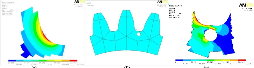
Copyright to IJIRSET www.ijirset.com 2753 (a)(b) (c) (d)
Fig.4.2.(a)Spur gear three teeth gear segment,(b). Finite Element Analysis of three teeth gear segmentsubjected to mesh,(c)Finite Element Analysis of three teeth gear segment subjected to boundary conditions,(d)Finite Element Analysis of three teeth gear segment subjected to load
(e) (f ) (g)
Fig.4.2.(e) Finite Element Analysis of three teethgear segment representing the principal stresses at different location,(f)Three teeth gear segment with stress relieving features,(g)Finite Element Analysis of three teeth gear segment with circular stressrelief features representing the principal stresses at different location
V. RESULTS AND DISCUSSIONS 5.1 To establish an empirical relation
This chapter deals withto establish an empirical relation for spur gear to predict the root fillet stress induced in gear geometry by consideringthree teeth segmentwith fully constrained conditions are discussed.
(a) (b) (c)
Fig. 5.1(a)Finite Element Analysis of three teeth gear segment subjected to load,(b)Percentage of reduction in root fillet stress v/s no. of teeth (c)Residual V/s Number of teeth
The graph in fig. depicts the third order polynomial fit to the data obtained by finite element analysis. It shows percentage of reduction in root fillet stress (maximum principal stress) verses number of teeth for the given rack cutter and the parameters of rack cutter considered for analysis are used. Pressure angle = 20° and tool tip radius = 0.2. The gears are generated using profile shift factor i.e., -0.2 to 0.2.
From fig(b) it can be seen that it is possible to predict the percentage of reduction in root fillet stress using the empirical relation proposed within a maximum error of 2%.
0 5 10 15 20
20 70
P
er
ce
n
tag
…
Number of teeth
0 0.3 0.6 0.9 1.2 1.5
20 30 40 50 60 70 80 90
R
es
idual
Number of teeth
Copyright to IJIRSET www.ijirset.com 2754 Fig. (c)Shows the variation of residual verses number of teeth for the different polynomial namely 2nd order, 3rd order and 4th order polynomial respectively. The graph shows the maximum residual is at number of teeth Between 60 to 70 and minimum residual is at number of teeth Between 40 to 50 for the 2nd order polynomial. The 3rd order polynomial shows that the maximum residual is at number of teeth at 80 and minimum residual is at 30 similarly for the 4th order polynomial the maximum residual is at number of teeth 40 and minimum residual is at number of teeth 30. Finally from the graph it is observed that the maximum deviation is in 2nd order polynomial and it is in accurate, also due to large data computation problem involved in the 4th order polynomial hence 3rd order polynomial eliminates inaccuracy and it performs the data computation easily so it is concluded that usage of 3rd order polynomial is essential.
VI. CONCLUSION AND SCOPE OF FUTURE WORK 6.1 Conclusion
Introduction of stress relieving features can be adopted without affecting the interchangeability and functionality of the gear of existing gear systems.
Slight reduction in root fillet stress results in large increase in fatigue life of gear.
It is possible to predict the percentage of reduction in root fillet stress with a maximum deviation of 2%. It also meets out the necessary kinematic constraints as the functional part of the gear profile is unaltered. The geometry of the spur gear created in an Ansys environment using APD Language and it eliminates the
problem of geometric data loss and time required to transfer the data from one modeling environment to analysis environment.
The analysis gives the maximum percentage of reduction in root fillet stress in spur gear is obtained about 18.032% for the gear parameters no. of teeth, profile shift factor, tool tip radius and pressure angle (80, -0.2, 0.2 and 25°).
It is desirable to use the 3rd order polynomial instead of 2nd and 4th order polynomial because it eliminates the problem of inaccuracy and large data computations which are involved in the 2nd and 4th order polynomial. The technique can be employed to improve further even on gears in which the stress reductions are already
achieved by modifying nonfunctional portion of the tooth profile.
6.2 Scope of future work
For further continuation of this work the following scope are specified:
The work presented is carried for static condition the method can be extended for dynamic analysis by defining the contact element.
The method can be extended for the fatigue analysis of gear. The comparative study can also be done by using three dimensional models and two dimensional models.
The method presented herein can be extended for the analysis of helical gears.
The method can be extended for the study the effect of bending stress for spur gear tooth with spokes. The method can be extended for wear analysis of gear tooth.
The method can be extended for vibration analysis and noise reduction. The method can be extended for the deflection analysis of spur gear.
REFERENCES
[1] Wilcox L. and Coleman W., "Application of Finite Elements to the Analysis of Gear Tooth Stresses," Journal of Engineering for Industry, Vol. 95, No. 4, Dec. 1973, pp. 1139-1148.
[2] Ferretted, L., Brown M., “Gear Stress Reduction Using Internal Stress Relief Feature”, Transaction of ASME Journal of Mechanical Design, Vol. 119, December 1997, PP. 518 – 521.
[3] Srinivasalu B, “Spur Gears- A new Approach in to Tooth Design” American Gear Manufacturers Association, Technical Paper 92FTMSI.
[4] Parker, R. G., Vijayakar, S. M., and Imajo, T., “Non-Linear Dynamic Response of a Spur Gear Pair: Modeling and Experimental Comparison”, Journal of Sound and Vibration, vol. 237, No. 3, pp. 433-455, 2000.
[5]Vijayarangan S. and Ganesan N., “Stress Analysis of Composite Spur Gear Using the Finite Element Approach”, Computers and Structures,
vol. 46, No. 5, pp. 869-875, 1993.
Copyright to IJIRSET www.ijirset.com 2755
[7] Math, V. B., and Chand, S., 2004, “An Approach to the Determination of Spur Gear Tooth Root Fillet,” ASME J. Mech. Des., 126_2_, pp. 336–340.
[8]Litwin, F.L., L. Qiming and A.L. Kapelvich, Asymmetric Modified Spur Gear Drives: Reduction of Noise, Localization of Contact, Simulation of Meshing and Stress Analysis. Computer Methods in App. Mechanics and Eng.,188:363-390, 2000.
[9] Hebbal .M.S., V.B.Math, B.G.Sheeparmatti “The reduction of root fillet stress in spur gear using circular and elliptical stress relieving
features”, International Conference, USNational Congress on Computational Mechanics, San Francisco USA, 22-26 July 2007.
[10]J.D.Andrews., “Finite Element Analysis of Bending Stress Induced in External and Internal Spur Gear”. Journal of Strain Analysis, vol.26,
No.3, 1991 PP153-163.
BIOGRAPHY