IJEDR1801078
International Journal of Engineering Development and Research (
www.ijedr.org
)
452
Analysis And Simulation Of Adaptive Power System
With Dc Motor Type Dynamic Loads
Ravi Kumar¹, Dr.Manish Kumar Srivastava² Department of Electrical Engineering
Sam Higginbottom University of Agriculture, Technology & Sciences, Allahabad, U.P, India
Abstract-In this paper proposes an Adaptive Power System (APS), it is used to mitigate the negative impacts levied on the platforms resulting from large dynamic loads. Here we are using dc motor because it has several advantages. Such as, Speed control over a wide range both above and below the rated speed High starting torque, Accurate steep less speed with constant torque etc. The Navy’s future and near-term high-energy sensors and energy weapons will consume a large portion of the resources of the intended ship platform. The APS has used to maintain generator/prime-mover reliability, and also it is used to improve sensor/weapon performance or improve metrics such as system weight, cooling demands, and ship fueling costs. A DC motor is any of a class of electrical machines that converts direct current electrical power into mechanical power. Many of these new systems will have extreme dynamic power profiles, including both periodic and aperiodic characteristics. By using the simulation results we can analyze the proposed method.
Keywords: AC/DC converter, DC/DC converter, synchronous machine, Adaptive Power System, Dc Motor, Simulink (Matlab).
________________________________________________________________________________________________________
INTRODUCTION
The APS is similar to the active filter concept whereby the active filter provides the current needed to maintain the quality of the load current required by the upstream power system. Duty cycles can vary from small to continuous and, for some cases, the peak power demands can be above the capability of the ship power plant. A DC motor is any of a class of rotary electrical machines that converts direct current electrical power into mechanical power. The most common types rely on the forces produced by magnetic fields. Nearly all types of DC motors have some internal mechanism, either electromechanical or electronic, to periodically change the direction of current flow in part of the motor. These types of extreme power profiles cannot be supported with conventional power systems.
The Adaptive Power System (APS) concept presented in this paper can be an enabling technology for sensors or weapons with large dynamic loads, which without the APS would be incompatible with the upstream shipboard generator and distribution bus. The APS consists of energy storage, a bidirectional current source, and innovative control
techniques. These innovative control techniques increase the energy storage utilization, thus minimizing the energy storage size. A block diagram of a conventional shipboard power system is shown in the Figure 1. Conventional systems have focused heavily on providing well-regulated voltages and clean power to the corresponding load. If the voltage dynamics seen at the load are to be minimized, the output impedance of each converter stage is minimized by using small series inductance values, large shunt capacitance values, and control loops with high bandwidths. However, to prevent the mid to low frequency load dynamics this type of system is presented from propagating back to the distribution bus and generator.
When compared with the passive filter method (brute-force method) the APS can support the pulsed load at a fraction of the size and weight needed. If using the active load method without excessive power dissipation as would exist (throw-away method), and for some specific applications without timeline restrictions as would be needed if using a refresh or recharging type system (restricted-timeline method).
Fig. 1. A block diagram of a notional power system with the APS attached
IJEDR1801078
International Journal of Engineering Development and Research (
www.ijedr.org
)
453
gensets by converting the dynamic power load seen by the shipboard power system into an equivalent rolling time average – essentially serving as an active low pass filter to the load dynamics. As shown in Figure 1, the APS can be added to an existing system. The APS consists of energy storage, a passive power filter, a bi-directional current source, and innovative control loops, as shown in Figure 2.Fig. 2. An overview of the functionality of the APS system.
The bi-directional current source efficiently delivers the pulsed power demand from the APS energy storage to the desired sensor or weapon system, thus providing a buffer to the upstream power equipment.
The APS is similar to the active filter concept whereby the active filter provides the current needed to maintain the quality of the load current required by the upstream power system. Active filters have been used for years in alternating current (AC) power systems to reduce the current harmonics and improve the power factor presented to the source when the loads are nonlinear and electrically noisy [10]–[12]. Induction motors ruled out all the motors in industries in every application. But DC motors were still used in certain applications where induction motors cannot fulfill the need. so, dc motors have its own significance in industries. This is because some special characteristics they possess.
DC motors were the first type widely used, since they could be powered from existing direct-current lighting power distribution systems. A DC motor's speed can be controlled over a wide range, using either a variable supply voltage or by changing the strength of current in its field windings. Small DC motors are used in tools, toys, and appliances.
With the proper use of control loops and energy storage, the APS can reduce the rate at which the power demand on the generator changes, thus limiting the dynamics and spectral content seen by the generator - transforming a weapon or sensor system that had otherwise been incompatible with the platform’s power system into one that is now feasible.
ADAPTIVE POWER S YSTEM (APS) A. Overview
The goal of the APS is to minimize bus disturbances and stress to prime-power equipment by converting the dynamic power load into an equivalent rolling average of the power demand. The APS is designed to meet the proposed requirement as shown in Figure 3.
Fig. 3. The power ripple filtering requirement of the APS
The APS implementation must also not interfere with maintaining a stiff voltage (tightly regulated voltage) to the load. The top-level components of the APS include the energy storage capacitance and two control loops. One loop controls the APS output current to provide the required dynamic current to the load using the energy from the storage capacitance, and the other loop maintains the voltage across the energy storage capacitance to within the allowed rating.
IJEDR1801078
International Journal of Engineering Development and Research (
www.ijedr.org
)
454
Operation of the Adaptive Power System is as follows:• The current provided from the upstream power system is regulated by the APS to be equal to the filtered (0.13 Hz) current profile of the load demand. The compensation block regulates Ibus to be equal to Iref by controlling the output current of the bi-directional current source (BDCS); see the bus-current and BDCS-current waveforms in Figure 2. The BDCS is a DC/DC converter that can process power in both directions – it can both absorb and deliver power.
• Hence, the AC component or dynamics of the load profile is not part of Ibus but is provided by the energy-storage capacitance via the BDCS.
• The energy-storage capacitance value is selected to be large enough to provide the source and sink currents to support the pulsed load demand. The value for the energy-storage capacitance is minimized by allowing the voltage across Cstore to vary significantly, where Udelivered = 1 2 Cstore(Vt20 − Vt2+), minimizing the energy storage capacitance required.
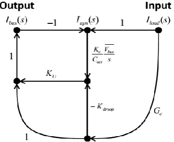
Fig. 4. Signal flow graph of APS for low frequency energy loop design where Ib u s = Iref and Iload = Iload.
– This provides significant weight and size savings compared to using an in-line high-powered low- pass filter (brute-force method).
– The voltage variation across Cstore is also decoupled from the load, allowing tight regulation of the bus voltage seen by the load to be maintained. Udelivered is the energy delivered or absorbed by the storage capacitance, and Vt0 and Vt+ are the corresponding voltages across the energy-storage capacitance just prior to the load disturbance and after the energy-storage capacitance has delivered or absorbed the desired energy.
B.APS Requirements for Notional System
To demonstrate the APS functionality and performance, a top-level design and simulation for a notional 300-kW systemwas performed. For this specific system the APS interfaces with the 375-VDC bus, as shown in Figure 1. The system was designed to support the following load and input–output performance specifications:
• Duty Cycle of Load: 0 to continuous • Average Load Power: 0 to 300 kW • Peak Load Power: 0 to 300 kW
• Input Voltage: 4160 VAC per MIL-STD-1399-680 • Input Interface Power Ripple Requirements: Figure 3
• Voltage Transients at the 375-V Bus Load Interface: maintain to better than ±5% C.APS Design Details for Notional System
Control Loop Bandwidth Considerations:
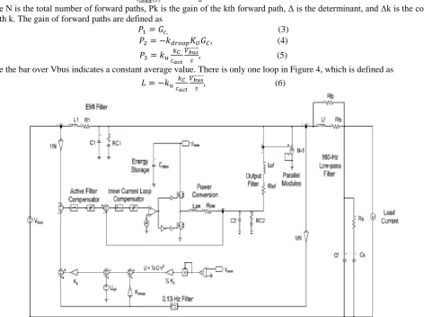
Figure 5 provides the schematic details for the APS. The bi-directional current source is a modular design consisting of thirty-eight 8-kW modules.
The sizing and performance for the BDCS is based on the bi-directional buck topology [17], using a 100-kHz switching frequency and average current-mode control. The switching frequency is chosen high enough to obtain the needed control loop bandwidths (which will give the desired APS filtering performance) but low enough to maintain acceptable switching losses. The inner current loop bandwidth of the bi-directional current source is set to be between 15 and 25 kHz (varies with the voltage across Cstore), allowing the outer current loop of the APS to be set at 4 kHz.
To simplify the analysis, the preceding assumptions have been used, and therefore this signal flow graph is only valid for low frequencies. In Figure 4, Ibus is the controlled upstream bus current coming from the 375-V converter, Iload is the current to the load before the 160-Hz filter, and Gc is the transfer function of the 0.13-Hz filter, which has been selected to be a second order filter defined as
𝐺𝑐 =
𝜔𝑐2
𝑠2+(2(𝜔𝑐)𝑠)+𝜔 𝑐
2 (1)
where ω c is the corner frequency (in rad/s) and ζ is the damping ratio. In this example, ζ is equal to 0.9.
IJEDR1801078
International Journal of Engineering Development and Research (
www.ijedr.org
)
455
𝐼𝑏𝑢𝑠(𝑠) 𝐼𝑙𝑜𝑎𝑑(𝑆)= ∑
𝑃𝑘∆𝑘 ∆ 𝑁
𝑘=1 (2)
where N is the total number of forward paths, Pk is the gain of the kth forward path, Δ is the determinant, and Δk is the cofactor of path k. The gain of forward paths are defined as
𝑃1= 𝐺𝑐, (3)
𝑃2= −𝑘𝑑𝑟𝑜𝑜𝑝𝐾𝑈𝐺𝐶, (4)
𝑃3= 𝑘𝑢 𝑘𝐶 𝑐𝑎𝑐𝑡
𝑉𝑏𝑢𝑠 ̅̅̅̅̅̅̅
𝑠 , (5)
where the bar over Vbus indicates a constant average value. There is only one loop in Figure 4, which is defined as
𝐿 = −𝑘𝑢
𝑘𝐶
𝑐𝑎𝑐𝑡
𝑉𝑏𝑢𝑠
̅̅̅̅̅̅̅
𝑠 , (6)
Fig. 5. The high-level schematic of an APS system used for simulation, where N is the total number of parallel modules (N=)38
The determinant is then
∆= 1 − 𝐿 = 1 + 𝑘𝑢
𝑘𝐶
𝑐𝑎𝑐𝑡
𝑉𝑏𝑢𝑠
̅̅̅̅̅̅̅
𝑠 (7)
Because the loop, L, touches all the forward paths, the cofactor for each forward path is simplify defined by ∆1= ∆2= ∆3= 1 (8)
Fig. 6. The bus current filtering performance of the APS with the proposed requirement overlaid (for example, a 100 kW average load is allowed 3 kW peak ripple at 1 Hz). Because the bus voltage is approximately constant, current filtering directly relates to
power filtering.
Figure 6 demonstrates that this equation’s predictions (black dashed line) are nearly identical to the detailed simulation results (solid blue line) up to 4 Hz, at which point interactions with the current control-loop compensator begins to appear. Figure 6 provides the time-constant requirement via the frequency-domain specification needed to determine the storage-capacitance nominal value, Cdesign.
This results since K droop’s units are Joules/Ampere. Knowing the amount of energy used, 𝑈𝑡𝑜𝑡𝑎𝑙= 𝐼𝑙𝑜𝑎𝑑𝑚𝑎𝑥𝐾𝑑𝑟𝑜𝑜𝑝 (9)
along with the maximum available energy for use
𝑈𝑚𝑎𝑥 =
1
2𝐶𝑑𝑒𝑠𝑖𝑔𝑛(𝑉𝑚𝑎𝑥
2 − 𝑉
𝑚𝑖𝑛2 ) (10)
IJEDR1801078
International Journal of Engineering Development and Research (
www.ijedr.org
)
456
𝐶𝑑𝑒𝑠𝑖𝑔𝑛=2𝐼𝑙𝑜𝑎𝑑𝑚𝑎𝑥𝐾𝑑𝑟𝑜𝑜𝑝
(𝑉𝑚𝑎𝑥2 −𝑉𝑚𝑖𝑛2 ) (11)
Here, Iloadmax is the designed maximum load current of the module, Vmax is the maximum allowed capacitor voltage, Vmin is the minimum allowed capacitor voltage.
TABLE I
SIZE ANDWEIGHT OF THEAPS SYSTEM
Table II provides a summary of predicted component losses. The MOSFETs used in the implementation of the BDCS are silicon carbide devices. Silicon carbide devices are selected because of the inherently low drain to source parasitic capacitance, which is crucial to minimizing the switching losses when operating at the high voltage levels with hard switching.
TABLE II
POWERLOSSES OF THEAPS SYSTEM
PROPOSED REQUIREMENTS
The Navy’s MIL-STD-1399-680 addresses pulse loading requirements, but only deals with pulses that occur infrequently – less than once every 45 seconds [14]. A requirement is needed that protects the genset and distribution bus against the dynamics resulting from frequent and repetitive pulsing loads but which is not as restrictive as the present requirement of only allowing a single pulse once every 45 seconds. Meeting the following requirement would provide this protection, and with the use of the APS, this requirement is feasible to implement, even for systems with large dynamic power profiles.
Proposed Pulsed Load Requirement:
The combined three-phase peak power ripple as seen by the shipboard generator(s) at any single frequency generated by the load shall be less than the limits defined by Figure 3. The resulting allowed load profile proposed in Figure 3 has been matched to the generator and prime mover performance. Typical gensets’ response times to a significant load change are on the order of 1.0 to 1.5 sec [15], [16]. If the rise and fall times for power changes (ramp rate) seen by the generator are controlled to be slower than the genset’s response times, the generator and prime-mover control loops will be able to maintain the voltage and speed regulation, bus disturbances will be kept to a minimum for such a slow-changing power profile, and sub-synchronous resonances will not be excited because the disturbances are at lower frequencies
DC MOTOR
A DC motor is any of a class of electrical machines that converts direct current electrical power into mechanical power. The most common types rely on the forces produced by magnetic fields. early all types of DC motors have some internal mechanism, either electromechanical or ctronic, to periodically change the direction of current flow in part of the motor. Most types produce rotary motion; a linear motor directly produces force and motion in a straight line.
Principle of DC Motor
This DC or direct current motor works on the principal, when a current carrying conductor is placed in a magnetic field, it experiences a torque and has a tendency to move. This is known as motoring action. If the direction of current in the wire is reversed, the direction of rotation also reverses. When magnetic field and electric field interact they produce a mechanical force, and based on that the working principle of dc motor established.
Fig.7 block diagram of motor energy conversions
IJEDR1801078
International Journal of Engineering Development and Research (
www.ijedr.org
)
457
The input and output port variables of the direct current motor are related by the parameter K.𝑇 = 𝐾𝐼 𝑎𝑛𝑑 𝐸 = 𝐾𝜔 (12) Description of a DC Motor
To understand the DC motor in details lets consider the diagram below,
Fig.8 Motor circuit diagram
The direct current motor is represented by the circle in the center, on which is mounted the brushes, where we connect the external terminals, from where supply voltage is given. On the mechanical terminal we have a shaft coming out of the Motor, and connected to the armature, and the armature-shaft is coupled to the mechanical load. On the supply terminals we represent the armature resistance Ra in series. Now, let the input voltage E, is applied across the brushes. Electric current which flows through the rotor armature via brushes, in presence of the magnetic field, produces a torque Tg . Due to this torque Tg the dc motor armature rotates.
The back emf like in case of a generator is represented by 𝐸𝑏=
𝑃.∅.𝑍.𝑁
60.𝐴 (13)
Where, P = no of poles φ = flux per pole Z= No. of conductors A = No. of parallel paths
and N is the speed of the DC Motor.
Due to this increased voltage difference, armature current will increase and therefore torque and hence speed increases. Thus a DC Motor is capable of maintaining the same speed under variable load. Now armature current Ia is represented by
𝐼𝑎= 𝐸−𝐸𝑏
𝑅𝑎 (14)
Now at starting, speed ω = 0 so at starting Eb = 0. 𝐼𝑎=
𝐸
𝑅𝑎 (15) B. Simulation results for Notional System
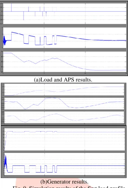
The DC/DC converter voltage control loop is set at 100 Hz. To demonstrate the effectiveness and benefits of the APS, Figures 9(a) and 9(b) provide simulation results for various waveforms in the system when a dynamic load is applied both with and without use of the APS.
IJEDR1801078
International Journal of Engineering Development and Research (
www.ijedr.org
)
458
(a)Load and APS results.(b)Generator results.
Fig. 9. Simulation results of the first load profile.
Figure 9(a) also shows the voltage waveform of the storage capacitor and the current waveform of the bi-directional current source, demonstrating the APS’s capability of providing the dynamic demand of the load resulting in the generator only having to provide the rolling average of the load power profile.
IV. CONCLUSION
In this paper the Adaptive Power System (APS) concept presented can be an enabling technology for sensors or weapons with large dynamic loads, which without the APS would be incompatible with the upstream shipboard generator and distribution bus. The APS consists of energy storage, a bidirectional current source, and innovative control techniques. A DC motor is any of a class of rotary electrical machines that converts direct current electrical power into mechanical power. The most common types rely on the forces produced by magnetic fields. These innovative control techniques increase the energy storage utilization, thus minimizing the energy storage size. The APS has used to maintain generator/prime-mover reliability, and also it is used to improve sensor/weapon performance or improve metrics such as system weight, cooling demands, and ship fueling costs. DC motors were the first type widely used, since they could be powered from existing direct-current lighting power distribution systems.The APS design is presented along with simulation results verifying the concept. By using the simulation results we can analyze the proposed method.
REFERENCES
[1] F. Kanellos, I. Hatzilau, and J. Prousalidis, “Investigation of voltage/frequency modulation in ship electric networks with pulsed loads according to stanag 1008 design constraints,” in All Electric Ship Conference, 2007.
[2] IEEE Recommended Practices and Requirements for Harmonic Control in Electrical Power Systems, IEEE Industry Applications Society/Power Engineering Society Std. 519-1992, 1993.
[3] M. Baldwin, “Electric arc furnace impact on generator torque,” in Power Systems Conference and Exposition, 2004. IEEE PES, 2004, pp. 776– 780 vol.2.
[4] G. J. Tsekouras, F. D. Kanellos, J. M. Prousalidis, and I. K. Hatzilau, “Stanag 1008 design constraints for pulsed loads in the frame of the all electric ship concept,” Nausivios Chora, vol. 3, pp. 113–152, 2010. [Online]. Available: http://nausivios.snd.edu.gr/nausivios/docs/b3 2010. pdf
[5] H. Smolleck, S. Ranade, N. R. Prasad, and R. Velasco, “Effects of pulsed-power loads upon an electric power grid,” Power Delivery, IEEE Transactions on, vol. 6, no. 4, pp. 1629–1640, Oct 1991.
[6] D. N. Walker, S. L. Adams, and R. J. Placek, “Torsional vibration and fatigue of turbine-generator shafts,” Power Apparatus and Systems, IEEE Transactions on, vol. PAS-100, no. 11, pp. 4373–4380, 1981.
[7] M. Butler, G. Dakermanji, L. Goliaszewski, D. Kusnierkiewicz, J. Tarr, D. Temkin, and U. Carlsson, “Fault tolerant shunt regulator for a spacecraft thermionic nuclear reactor,” AIP Conference Proceedings, vol. 324, no. 1, pp. 39–44, 1995. [Online]. Available: http: //scitation.aip.org/content/aip/proceeding/aipcp/10.1063/1.47196