Flow Visualization of a Scramjet Inlet - Isolator Model in Supersonic Flow
S. Seckin1, K.B. Yuceil2 1
Graduate Student, Dept. of Astronautical Engineering, Istanbul Technical University, 34469 Maslak, Istanbul, Turkey 2
Asst Prof., Dept. of Astronautical Engineering, Istanbul Technical University, 34469 Maslak, Istanbul, Turkey
Abstract. Understanding the physical mechanisms and having insight to the complex flowfield involving unstart phenomena in supersonic inlets has gained considerable attention especially in the area of scramjet inlet/isolator aerothermodynamics. In this study, Schlieren visualization and computational analysis of shock wave structures in ramjet/scramjet inlet/isolator models in supersonic flow have been performed. Experiments were performed in the supersonic wind tunnel at the Trisonic Research Laboratory in Istanbul Technical University. The test section floor and the existing mechanism underneath have been modified to be able to mount the designed inlet/isolator model on the floor of the test section. The inlet/isolator model with a 12-degree compression ramp is investigated at Mach 2 both computationally and experimentally. Computations were performed using Star-CCM+ software to investigate shock wave structures in and around the three dimensional inlet/isolator model as mounted on the test section floor as a guide for designing the experimental model. In the results, the effects of shock wave – boundary layer interactions with flow separations with were observed. Ensemble average of the density distributions on a series of planes from one side wall to the other from the CFD results agreed well with the Schlieren images obtained experimentally. The structure of the shock waves and angles obtained from the Schlieren images agree quite well with those obtained from the CFD results. The effects of lambda-shock formations which indicate possible boundary layer separations, reflections of shock waves, and shock wave – boundary layer interactions on inlet unstart phenomena have been discussed. In order to investigate inlet unstart mechanism further, different experimental setups have been suggested for future work.
1 Introduction
Developing reliable and affordable ramjet and scramjet propulsion technologies is vital for realizing routine supersonic and hypersonic transport. Ramjet/Scramjet engines are air-breathing engines that use the surrounding air as a working fluid. High Mach number air is first slowed down and compressed by the inlet/isolator prior to mixing with fuel and then sent to the combustor. Hot exhaust gases pass through a nozzle and produce thrust. Ramjet/Scramjet uses forward motion of the vehicle to compress incoming air at the inlet instead of a rotary compressor in conventional jet engines. Therefore, they have less moving parts and they are much lighter than turbine engines.
In ramjet, air is slowed down to subsonic speeds by a system of shock waves in the inlet/isolator. Therefore, the combustion takes place at subsonic speeds. Hot combustion gases are accelerated through a convergent-divergent nozzle to supersonic speeds. Inefficiencies regarding performance loses occur due to shock waves in the inlet/isolator. Also, thermal and mechanical loads
increase on the combustion chamber walls. Because of these performance limitations, ramjet propulsion is not suitable speeds above Mach 5 [1].
In scramjet (supersonic combustion ramjet), although the incoming flow is slowed down and compressed through the inlet, combustion process occurs supersonically. Therefore, the engine is less susceptible to total pressure losses than the ramjet due to weaker shock waves and is relatively more efficient for hypersonic flight. Also compared to rockets, which must carry their own oxidizer, scramjet engines are more efficient for a flight in the atmosphere [2]. Developing scramjet technologies will lead to vehicles with affordable and reusable air-breathing hypersonic engines such as cruise missiles; long range aircraft and space-access vehicles for taking off and landing such as airliners [3].
In figure 1 a schematic of a scramjet is shown. Forebody provides the first compression of airflow. Shock waves in the inlet/isolator convert the dynamic pressure due to the velocity of incoming air into higher
This is an Open Access article distributed under the terms of the Creative Commons Attribution License 2 0 , which . permits unrestricted use, distributi and reproduction in any medium, provided the original work is properly cited.
on, C
static pressur figure 1 and pressure and through shock
F
For ram that adjusts th the combustio precombustio in figure 2 [ process, static pressure rise of the isolato unstart which may lead to engine failure
Hyperso extraordinary aspects. Thes
‐ Very high ‐ Heating o ‐ Steady-sta
shock wav ‐ High aero ‐ High fluct ‐ The poten and therm ‐ Erosion fr
the engine
By dev materials and
re. The shock d Mach num d temperature
k waves.
Fig. 1. Schemat
Fig. 2. Scramj
mjet/scramjet, he static back on, boundary on shock appe [3]. Due to i c back-pressu can force the or and inlet. h produces un more catast e.
onic vehicle y challenges fo
e are [3]:
h temperatures f the whole ve ate and tran ves
dynamic load tuating pressu ntial for sever mally induced s from air flow
e
veloping tec d more exper
k train can b mber is redu e increase al
tic of a scramje
jet components
isolator is a c k-pressure. At layer starts t ears in the iso nstabilities in ure changes in shock waves This conditio ndesirable inl trophic conse
es are subj for both struct
s ehicle
sient localize
ds ure loads
re flutter, vibr stresses
over the veh
chnology, ne riments are d
e seen clearl uced while s long the isol
et [4].
[3].
critical compo t the beginnin to separate an olator as show
n the combus n the isolator. s to be pushed on is called i et conditions equences such
ject to sev tural and mat
ed heating f
ration, fluctua
hicle and thro
ew research done on scram
y in tatic lator nent ng of nd a wn in stion The d out inlet and h as veral erial from ating ough on mjet prop spa futu Cur con mod tran hyp prop und imp dev Mo spe the and geo wav
In o stud Uni curr to a floo cap sum incl and imp exp 2 E 2.1 Exp Win is a ach with stud the exp of q perf tran floo prev wal The axis How suit axis the the floo pulsion, hype ce access an ure.
rran and Stu ncept in which
de at lower su nsition to sc personic fligh posal in 19 derstanding proving the veloping metho re recently, ed Schlieren unstart proce d found out th ometry and th
ve boundary la
order to initi dies on scram iversity a pre rent study. W allow for mo or and provi
abilities to in mmarizes som
luding shock d the computa prove the proc perimental mo
Experimenta
Mounting a
periments wer nd Tunnel at I a blow-down hieved by usin h ranges of 0 dy, the test sec Mach numb periments. The quartz for sch
forated floor a nsonic flow r or and ceilin vents mountin lls.
e tunnel has symmetric m wever, the inl table for mou symmetric sha back of the m
inlet/isolator or using a set
ersonic flight nd long dista
ull [5] propos h the engine upersonic flig ramjet mode ht Mach numb
63, much w the comple performance ods of practic
optical flow and PIV hav ess in an inlet at unstart was he separated
ayer interactio
ate and build mjet inlet uns eliminary wo ind tunnel tes ounting super sions have b itiate unstart i me of the effo wave visualiz ational analys cess of design
del to be used
al Setup
apparatus se
re carried out Istanbul Techn type and has g two differen 0.4 – 2.1, and ction with the ber is set to
e tunnel has t hlieren visualiz
and ceiling fo regime. The p ng and the b
ng the model
s a stick-typ odels in the let model use unting to the ape and off-ce model. Becau model is mo t of floor plu
will be avai ance transpor
sed the dual-is allowed to ght Mach num e at higher
bers. Since t work has be ex flowfield e of such
al implementa
diagnostics ve been used
t-isolator mod s strongly infl
flow resultin ons [21,22].
d the infrastru start at Istan ork has been st section has b rsonic inlet m been made to in such mode orts made in
zation by sch sis which are ning and man d in the wind t
etup and mo
in the 151 nical Universi s two Mach n nt nozzle-test d 0.4 – 4.0. I e range 0.4 – 2 2.0 for the two circular w
zation on its s or boundary la presence of t boundary laye ls on either u
pe support center of the ed in the expe
e support du enter point of use of these in ounted on the ugs, which wa
lable both fo rtation in the
-mode engine o act in ramje mbers and then
supersonic to the dual-mode een done fo ds involved engines, and ation [6–20].
such as high to investigate del at Mach 5 luenced by the g from shock
ucture for the nbul Technica n done in the
been modified models on the o add furthe
ls. This study that direction hlieren method performed to nufacturing the tunnel. odifications
5 cm Trisonic ity. The tunne number range section block In the presen 2.1 is used and e visualization windows made side walls and ayer suction in the perforated er mechanism upper or lowe
for mounting e test section eriments is no ue to its non f attachment in
nconvenience e wind tunne as designed to
replace the o suction mech stainless steel original perfo redesigned as inner plug (l model from shown in figu different mod piece and can access.
Fig. 3. Mount
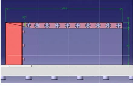
In the presen an inlet with of incoming representing scramjet eng represents a r the body of an acts as the f photo of the m
Fig. 4. Test
2.2 Inlet/Iso
Inlet de primary sho compression creates shock flow. As show through an ob
riginal tunnel hanism. Figu l floor plug (la orated brass f s having a sl labeled as 2 the bottom ure 3. This in dels without h n be replaced
ting apparatus a
t study, the m a ramp provid air flow, an the link to t gine. The d ramjet/scramj n aircraft. The forebody of th model mounte
t section modul inlet/isolator
olator design
esign of a ram ock wave f
of the incom k wave is a ram
wn in figure 5 blique shock
l floor with it ure 3 shows abeled as 1) w floor of the w lot to accomm in figure 3)
and underne nner plug also having to chan
with another
and inlet/isolato
model is a sim ding entrance nd a straight the combustio designed inle et inlet that i e lower wall o he vehicle. F ed on the wind
le for Mach 2 a r model assemb
n and calcul
mjet/scramjet formation an ming air. The mp which defl 5, incoming ai wave with an
ts boundary l s the new s which replaces wind tunnel.
modate a thi for attaching eath the floor
allows moun nge the new f r one with op
or model assemb
mple duct that and compres t isolator sec on chamber o et/isolator m
is mounted un of the wind tu Figure 4 show d tunnel.
and the designed ly.
lations
is critical du nd the resul e mechanism flects incoming
ir flow at M1 g ngle due to
layer solid s the It is icker g the
r as nting
floor tical
bly.
t has ssion ction of a model
nder unnel ws a
d
ue to lting
that g air goes o the
ram
M2 norm Rel and
max abo mod max exc Det ram flow
in s cho dire obs inle refl inte with ana
can sho
mp and the flo where Mn1 an mal to the lationship betw d the incoming
tan
Fig
Since the ex ximum determ out 22.97° for
del facing the ximum angle eeded, a de tached bow sh mjet/scramjet b w behind the s
In order to supersonic ra osen as 12° a
ection is from serve shock w et/isolator mo lections, and eractions and h the help of alyses which w
Fig. 6. Schem
For the firs n be obtained f ock wave theor
w deflects by nd Mn2 are the shock for M ween the def g Mach numbe
2 cot
g. 5. Oblique Sh
xperiments ar mined ramp an
air. Therefor e freestream, because whe etached bow
hock wave is because it can shock wave be
keep the velo ange, ramp an as shown in m left to the ri wave reflectio del is 160 mm
to prevent sh inlet unstart, f Computation will be discuss
matic side view o
t shock wave, for M1 = 2an ry as 1.565 wh
y an angle of θ
e Mach numbe
M1 and M2, flection angle er is given by
hock Geometry.
re carried out ngle θ from e re, all the ram
should be sm en the maximu
shock wav an undesired lead to inlet u ecomes subso
ocity behind t ngle of the i figure 6 wh ight. In order ons, the total
m. To observ hock wave b the height is nal Fluid Dyn sed in further s
of the inlet/isola
, downstream nd θ = 12° ram
hich is still su
θ with a speed er component
respectively e, shock angle
(1)
.
at Mach 2, the equation (1) i mps of the inle maller than thi um θ angle i e is formed d condition fo unstart and the
nic.
the first shock inlet model i here the flow r to be able to length of the ve at least two oundary laye
set to 50 mm namics (CFD sections.
ator model.
Mach numbe mp angle using upersonic.
d s y. e
e s et s s d. or e
k s w o e o er m D)
When v the side wall which is again To be able to which is the t test section ar designed inl satisfies the re
Fig.
The inle of 5 pieces fo parts numbere due to streng made of Ple visualize shoc
Also to the fasteners differences o outside of th between the leakage. In or model the sm with model w
F
viewed from th ls of the mo n below θmax f o start the wi total projectio rea, should be let/isolator m equired condi
7. Top view of
et/isolator mo or the sake of ed by 4 and 5 gth considera exiglas since ck waves with
minimize th s were embe on the walls he inlet/isola
connections rder to provid mall cavities in wax as shown i
Fig. 8. Inlet/isola
he top, the out del have bee for M = 2 as s ind tunnel, th on area of the e below 15%. model is abo
tion.
f the inlet/isolato
odel was desig f manufacturin in figure 3 w ations and th it had to b h the Schlieren
he interference edded. Due between the ator liquid s
of the parts de a smooth a n the heads of in figure 8.
ator model asse
ter ramp angle en chosen as shown in figur he blockage r
model divided . The ratio for out 5.7% w
or model.
gned as consis ng simplicity. were made of b e number 3 be transparen n method.
e in the flow to the pres e inside and
ealant was u s to prevent airflow around f bolts were fi
embly.
es of 20° re 7. ratio, d by r the which
sting The brass was nt to
w, all ssure
the used any d the filled
3 C
For inle CCM the cha Aft thes
3.1
The For
‐ ‐ ‐ ‐ ‐ ‐ ‐
dec sho Sin eno som situ
Fig.
3.2
Sin muc flui imp
Computation
r the analys et/isolator mod
M+ software problem w aracteristics o
erwards, a 3D se studies will
2D CFD An
e problem wa r Mach 2, the p
Two Dimens Inviscid Gas Coupled Flo Ideal Gas Coupled Ene Steady
This fast so ide the dime own in figure
ce y-momentu ough, solution mewhat artific uation.
. 9. Mach numb
3D CFD An
ce the actual ch better defi id flows is mo ported into Sta
nal Configur
sis of the f del and the wi was used. Fir was carried of shock wav D fine solution
l be explained
nalysis
as run with 43 physical mode
sional
ow
ergy
lution with a ensions of th 9 at least two um of the re n at the back cial and does
ber distribution
nalysis
l flow is 3D ned case was odeled as soli ar-CCM+ as s
rations
flow in and ind tunnel test rst, a 2D coar out to un ves and expa n was employ d in further sec
3293 cells and el was selecte
a coarse mesh he experiment o reflections w esiduals was n side area of s not represen
of the 2D inlet
D, viscous and run. First, th id and the CA
hown in figur
d around the t section, Star rse solution o nderstand the
ansion waves yed. Details o ctions.
d 86198 faces d as:
h was done to tal model. A were observed
not converged the isolator i nt the correc
t/isolator model
d turbulent, a he volume tha AD model wa
re 10.
e r-of
e s. of
s.
o s d. d s ct
l.
Fig
For the was selected Since the fl boundary lay Layer Meshe option. Also selected for a
Fine me computationa number of ce were created step. Maximu 16, 32 and 64 on the walls w was set as 1. 20, which cre layer thicknes size between set to 1.1 and
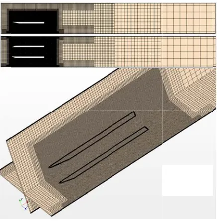
The res 21864559 fa different view in order to ha this also pre iteration.
For the were chosen t
‐ Three Di ‐ Gas ‐ Coupled ‐ Ideal Gas ‐ Coupled ‐ Turbulen ‐ Reynolds ‐ Spalart-A ‐ Standard ‐ All y+ W ‐ Steady
g. 10. CAD mo
computation since it was s low is visco yer interaction er was selec o Trimmer a good volume
esh is not requ al domain; the ells and save c
with mesh si um Cell Sizes 4 mm in that o were set to 2 m
1. Number of eated twenty l ss. Also for a different reg Template Gro
sulting mesh aces as show ws. The back s
ave better con evented the r
Physical Mo to define the p
mensional
Flow s
Energy nt
s-Averaged N Allmaras Turb Spalart-Allm Wall Treatment
del of the flow
nal grid hexah suitable for th ous, to obser ns and flow s cted in the M and Surface e mesh.
uired in every erefore in orde computation t izes becoming
of the region order. Prism L mm and Prism f Prism Layer layers in the a slow transiti gions, Surface
ow Rate was s
consists of 7 wn in figure side of the mo nvergence for reverse flow
odels selectio physical condi
Navier-Stokes bulence maras
t
region.
hedral mesh his kind of flo rve the shoc separations, Pr Meshing Mo
Remesher w
ywhere within er to decrease time, five reg g bigger in ev s were set to Layer Thickne m Layer Stretch
rs was define defined boun on of surface e Grow Rate
set as slow.
307598 cells e 11 from t odel was kept l
better results warnings du
on, the follow itions in the co
type ows. ck -
rism odels were
n the e the gions very 1, 4, esses hing ed as dary cell was
and three long and uring
wing ode:
assu stea the mod Wa
tunn defi con are con con tem Ref defi init clos init
con CFL step
3.3
Ma Acr with aga num with the dow incr
Fig. 11. G
This proble umptions. Firs ady and the f
flow is turb del was used all Treatment w
In the CFD nel is defined fined as outl nditions for in used for a nditions which nditions are mperature of th ference Pressu fined as 288 K ial 500 m/s v se to the two
ial condition.
Even if it nvergence, Co L number, is t ps, it was obse
3D CFD An
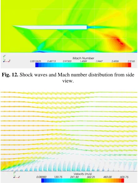
When view ch number dis ross the first s h the help o ain where it r mber. But, in h boundary la
pressure d wnstream of th
reases signific
Grid structure f
em is analy st of all it was fluid was stan bulent and S d. For the tur
was selected.
model the e d as inlet and let. In order nlet and outlet freestream M h are selected
obtained as he airflow at ure Also out K. For a fast s velocity in the times the sp
takes more t ourant Numbe taken as 0.1 f erved that sho
nalysis Resu
wed from the stribution clea shock wave M f the expansi reaches nearly the regions w ayer, the flow ifference bet he shock wav cantly especia
from different v
yzed using t s assumed tha ndard air as id Spalart-Allmar rbulent bound
entrance of th the exit from r to define
t, isentropic f Mach number d to match the
s 160 K fo the inlet and tlet static tem solution of th e x-direction, peed of sound
time to solve er, which is a for this proble ck waves settl
ults
side as shown arly shows the Mach number ion wave, flo y to the free where shock w w slows down tween upstre ve, boundary l ally in the area
views.
the following at the flow wa
deal gas. Also ras turbulence dary layer y+
he flow to the m the tunnel i
the boundary flow equation
r of 2. Flow e experimenta
or the static d 33670 Pa a mperature wa he problem, an
which is very d is defined a
e, for a bette also known a em. After 1270
led enough.
n in figure 12 e shock waves
decreases bu ow speeds up
stream Mach wave interact n. Because o eam and the
ayer thicknes a of interaction
g s o e +
e s y s w al c s s n y s
er s 0
x
with the first shock waves. on the wall appears. Sho direction and figure 13 bo clearly for t interaction. T
x-direction is separation. Th because due t reflection fro number appea represent the wind tunnel.
Fig. 12. Shock
Fig.
When v observed as angle at the ti of the ramp f to be stronger
t shock wave . This thick b and for this ck waves co d their strengt oundary layer the first sho The velocity ve s the indica he red region to the expans m the side w ars as maximu
real situatio
k waves and Ma v
13. Boundary l
viewed from t shown in fig ip from the to from the side r as shown cle
since it is th boundary laye s reason anot ontinue by re
th decrease. A r separation ock wave –
ectors that poi ation for the
in figure 12 c sion waves at walls of the w
um in this are n in the flow
ach number dis view.
layer separation
the top, simil gure 14. Sinc op view is high view, the sho early in figure
he strongest o er acts as a bu
ther shock w eflecting along Also as show
can be obser boundary l int in the nega
boundary l can be mislea the back and wind tunnel, M
ea which does w rather than
tribution from
n vectors.
lar conditions ce the deflec her than the a ock wave app
14.
f all ump wave g x -wn in
rved layer ative layer ding d the Mach s not n the
side
s are ction angle pears
the the As side bett wav sect num num the spa mm is a to th prob refl Num inle pro fron stru win Sch ima The one wer crea exp com sect
Fig. 14. Mach
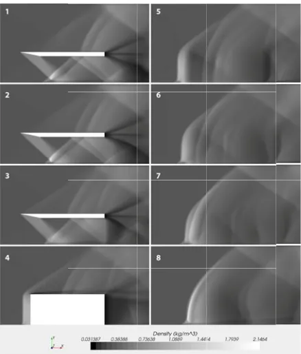
Using dens CFD analysi Schlieren met shown in figu e view help ter due to the ve. By startin tions of the d mbered from mber 2 represe
center in th cing continue m away from th
at 75 mm. Sinc he center plan blem. From n lections can b mber 4 is the et/isolator ver
file of the 20 nt. Numbers ucture betwee nd tunnel sid hlieren method age is affec erefore, the av e side to the o
re calculated ating the ave pected Schlier mpared with
tions.
h number distrib
sity distributio is has been co
thod is related ure 15, the de understand t sudden densi ng from the c density distribu 1 to 8. Numb ents the cross he spanwise es until numb he center and ce the solution ne, only one si number 1 to n be clearly obs e cross sectio rtical wall. Th
angle tip ra from 5 to en outside of de wall. Sin d go through t cted by all verage of all th
other side of by exportin rage final im en image is s experimenta
bution from the
on to visualize onsidered app d with the den ensity distribu the shock wa ity change acr centerline, sid ution are show ber 1 represen s section 10 m
z-direction. ber 8 which
the wall of th n is symmetri ide is enough number 3, sho served in the on where oute
his shows the amp of the sid
8 show the f the inlet/iso nce the light the z-direction
cross sectio he solution of
the wind tun ng results to mage by using
shown in figur al results in
e top view.
e the results o propriate since nsity gradients utions from the
ave structure ross the shock de view cros wn in figure 9 nts center and mm away from The 10 mm represents 70 he wind tunne
ic with respec to analyze the ock waves and inlet/isolator er side of the e shock wave de walls in the shock wave olator and the t rays in the n, the resultan
onal regions f the cells from nnel side wall
Tecplot and g Matlab. The re 16 and it i n the furthe of
Fig. 15
Fig. 36. A
4 Experime
Experiments w wind tunnel Faculty of A Technical Un the same resu
As calc and 12 ramp Also for Mach as:
The str schematically exact values. line originatin
. Density distrib
Average density
ntal Results
were perform in the Trison Aeronautics a niversity. In th ults were obtai
culated in the p angle, from h 2 the angle
sin
ructure of t y in figure 18 According t ng from the tip
butions from th
distribution alo
s
med at Mach 2 nic Research L
and Astronau he repeated ex ined as shown
previous sec equation (1), of the Mach w
1
sin 12
the shock w and the angle o the approx p of the 12 r
he side view.
ong z-direction.
in the supers Laboratory at utics of Istan xperiments ne n in figure 17.
ctions for Mac
β angle is 41 wave is calcul
30°
waves is dr s do not repre imate sketch, ramp as numb
onic t the nbul early
ch 2 1.6°. lated
rawn esent , the ered
by calc this tunn form stru the sma the com sho laye bou with exp occ form
F
sho con the look is c wal 6 is Ma the inle win obs
1 is a shock culated β ang s shock wave nel floor. Bec ms in this re ucture of the C experimenta aller lambda-s boundary la mpared to th ocks are the in
er separations undary layer h the reverse v periments an urs as indic mation.
Fig. 47. Schlie
Fig. 18. Shock w
The shock ock wave nu ntinues on unt
shock waves ks as if they a caused by the lls of the inlet s very close to ch wave or a outer tip with et/isolator and nd tunnel inn served better in
wave becaus gle compared e interacts w cause of this i egion. It is CFD results in al results in
shock is form ayer in CFD
at of the wi ndicators of t s. As mention separations w velocity vecto extensive b cated by su
eren image of th
wave structure f
wave numbe umber 2 is
il the shock n numbered by are different fr refraction of t/isolator. The o that of a Mac weak shock. h an angle of d it is betwe ner walls. T n figure 15 fro
se the angle i to the Mach ith boundary interaction, a
clearly show n figure 19 is v
figure 18. A ed in the CFD analysis is ind tunnel w the possibility ed in the prev were observed or profiles. Th boundary lay uch a big la
he inlet/isolator
from the experim
ered by 1 ref formed. Th number 4 is fo y 4 and 5 are t from each othe f the light by e angle of the
ch wave and i Number 7 is 20 of the sid een inlet/isola This shock w
om images thr
is close to the angle, , and layer on the lambda-shock wn that shock very similar to A similar bu D results since
much thinne walls. Lambda
y of boundary vious sections d in figure 13 herefore, in the yer separation ambda shock
r at Mach 2.
mental result.
flects and the his reflection ormed. In fact the same but i er because thi Plexiglas side
wave numbe it is probably a
formed due to de walls of the ator walls and wave can be rough 5 to 8.
e d e k k o ut e er a y s, 3 e n k
Fig. 19.
In sum boundary lay increases and separations. A the separated prevent un separations sh
5 Conclusio
In this pape investigated experimentall wave structu interaction be shows the po waves have a thickness. Th formation of have an impo at supersonic placing a flap flap angle, investigated technique can about the fl unsteady surf can be perfor behavior of th
References
1. Ramjet from N 12/airpla 2. Scramje
from N 12/airpla 3. D. Andr
27, (200 4. How Scr
from N news/fac 5. E. T. Cu RTD-TD
. Shock wave st
mmary, when yers, the thic d lambda-sho A second sho boundary lay nstart, shock hould be inves
on
er, a supers at Mach 2 ly. With the h ure of the in etween shock ossibility of a big effect on his thickened a second sho ortant role on c Mach numb p in back of unstart cond further. Parti n be used to o
low field w face pressure rmed to gain a he flow and th
Propulsion. NASA: http
ane/ramjet.htm
et Propulsion. NASA: http ane/scramjet.h readis, The Ind 04)
ramjets Work
NASA: http://w ctsheets/X43A urran and F. E DR-63-4097, (
tructure in the C
shock wav ckness of the cks occur as ock wave form yer. In order t
k-induced b stigated in mo
sonic inlet/is 2 both com help of CFD a nlet/isolator i k waves and
flow separati n increasing th boundary lay ock wave. Al
inlet unstart bers. For the
the isolator a ditions can
cle Image V obtain quantit within the in
measurement a better idea a he unstart proc
(n.d.). Retrie ://www.grc.na ml
. (n.d.). Retri ://www.grc.na html
dustrial Physi
k. (n.d.). Retri www.nasa.go A_2006_5.htm
E. Stull, Aero (1964)
CFD results.
ves interact w e boundary l
a result of f ms at the bac
to understand boundary l ore detail.
solator mode mputationally
analysis the sh is obtained. boundary la ions. Also sh he boundary l yer can cause ll of these eff which may o future work and adjusting be induced Velocimetry (P tative informa let/isolator. A ts within the i about the dyna cess.
eved April 2 asa.gov/WWW
eved April 2 asa.gov/WWW
icist, AugSep,
ieved April 2 v/centers/lang ml
o Propulsion L with layer flow k of
and layer
l is and hock The ayers hock layer e the fects
ccur k, by
g the and PIV) ation Also inlet amic
012,
W/k-012,
W/k-,
24-012, gley/
Lab., 6.
7.
8.
9.
10
11
12
13
14
15
16
17
18
19
20
21
22
E. T. Curr Annual Rev (1996) W. H. Hei
Breathing
AIAA, Was S. Emami,, Weidner, NA C.-P. Wang
Paper 2006
. N. Bachcha
4716, (2004 . K. Matsuo, in Aerospac . P. J. Waltru
10, 1404–14 . P. J. Waltru
and Rockets . B. U. Reina Journal of (2003) . G. Sullins,
5104, (1992 . C.-J. Tam
Behdadnia, . S. K. Stouf
2001-0519, . J. A. Hudge
3101, (1991 . G. Masuy Shinozaki, A of Propulsio . D. M. Van W
Paper 96-29
. J. L. Wagn Clemens, an 1528-1542, . J. L. Wagn AIAA Journ
ran, W. H. , view of Fluid
iser, and D.
Propulsion, shington, D.C
C. A. Trexler
NASA TP-3502
g, K.-Y. Zhan
6-818, (2006) an, and R. H 4)
Y. Miyazato ce Sciences, 3
up, and F. S. 408, (1973). up, and F. S. B
s, 10, 9, 620–6 artz, C. D. Her
Propulsion an
and G. Mc 2)
, K-C. Lin,
AIAA Paper 2
ffer and M. A (2001) ens, and C. A 1)
ya, T. Kom A. Nakamura, on and Power, Wie, F. T. Kw
914, (1996) ner, K. B. Y
nd D. S. Dol (2009) ner, K. B. Y nal, 48, 9, 187
Heiser, and d Mechanics,
T. Pratt, Hy AIAA Educ ., (1993) r, A. H. Ausle
2, May (1995) ng, and K.-M.
Hillier, AIAA
o, and H.-D. K
5, 1, 33–100, Billig, AIAA
Billig, Journal 622, (1973) rrmann, and J nd Power, 19
Lafferty, AIA
, D. L. Da
2006-4509, (2 A. Hagenmaier
A. Trexler, AI
muro, A. M , and O. Mura , 11, 2, 301–3 wok, and R. F
Yuceil, A. Va lling, AIAA J
Yuceil and N. 75-1888, (201
d D. T. Pratt
28, 323-360
Hypersonic Ai
cation Series
ender, and J. P
Cheng, AIAA
Paper 2004
Kim, Progres (1999) A Journal, 11
l of Spacecraf
. B. Ballmann
9, 5, 868–875
AA Paper 92
avis, and R 2006)
r, AIAA Pape
IAA Paper 92
Murakami, N ayama, Journa 07, (1995). . Walsh, AIAA
aldivia, N. T Journal, 47, 6
. T. Clemens 0)
t, 0,
r
s,
P.
A
4-s
1,
ft
n, 5,
2-R.
r
-N. al
A
T. 6,
![Fig. 2. Scramjjet components [3].](https://thumb-us.123doks.com/thumbv2/123dok_us/8988054.1436936/2.612.78.297.120.401/fig-scramjjet-components.webp)