4090
Influence Of Ampoule Diameter On Structure Of
TlBiTe2 Crystals
G. A. Gamal, M.A.K. El-Fayoumi, M.A. Morsi,H.S.Hamdy, M.A.Sebak
Abstract: X – ray analysis technique, for two grown crystals, was applied to obtain many crystal parameters like crystal lattice, grain size, micro-strain, dislocation density, dislocation arrangement, and the distance between two dislocations of TlBiTe2. Two crucibles (1.3 cm and 1.5 cm) were used for growing the crystals. This enabled us to compare influence of the ampoule diameter on the crystal quality in the framework of the Marangoni effect. The crystals were grown by a special modification of the well-known vertical Bridgman – Stockbarger technique. The Bragg peak line profile analysis of TlBiTe2 crystals were done by using Scherer's equation, Williamson – Hall plot, and Warren - Averbach method. We concluded that the grown crystals are rhombohedral TlBiTe2 crystals. Results showed that the n-type TlBiTe2 is a very sensitive semiconductor the growth conditions especially the ampoule diameter..
Index Terms: TlBiTe2, Crystal growth, Growth conditions, Ampoule diameter, Marangoni effect, Semiconductor crystals, Lattice parameters, Dislocation density, Crystallite size, Micro strain..
—————————— ◆ ——————————
1
INTRODUCTION
The compound TlBiTe2 belongs to materials of the type TI-V-VI2 (where V: As, Sb, Bi and VI: S, Se, Te). Several research studies have been conducted on this crystal and could reveal attractive physical properties (1-2). In fact, no extensive studies on the TlBiTe2 compound have been performed so far because of difficulties in obtaining well-defined single crystals. The literature on TlBiTe2 is rather meager. However the papers which have already been published cover many fields. In this way the compound TlBiTe2 is well known semiconductor and its properties are established. This enables us to study the influence of the growth conditions on the crystal quality (3). K. M. Yulin Chen et al.(4) have mentioned that TlBiTe2 may be a candidate for topological superconductors. Hockings and White (53) determined that melting point as 535 C and the structure was a rhombohedral (118), ordered in the sequence Tl- Te-Bi-Te. E. K. Polychroniadis et al.(5) have studied crystal growth and specimen preparation for thermoelectric materials (TEM) on bulk TlBiTe2. D. Coquillat et al.(3) have investigated thermal and optical properties of TIBiTe2 crystals. N.S. Popovich et al.(6) have investigated the conditions of TlBiTe2 formation through a thermal study. Recently (3) new results on the phase diagram of T1-Bi-Te have studied the conditions of preparation of a single-phase crystal and has been described as a rhombohedral phase with R3m space
group. The lattice parameters are aR = 8.118
A
, αR = 32.27o. Ken Kurosaki et al.(7), studied thermoelectric properties of TlBiTe2.In that work polycrystalline samples of TlBiTe2 have been prepared Also many physical properties (thermoelectric, electrical resistivity and Seebeck coefficient) have been investigated.The Seebeck coefficient of TlBiTe2 is negative in the entire the temperature range, showing n-type semiconductivity. It is concluded that ternary chalcogenide TlBiTe2 and TlBiSe2 have been proved to be promising technological insulators. F.I Akhmedovs et al.(2) have also investigated electrical properties of TlBiTe2. It is an established fact that there are many other parameters that can help for growth of high quality crystals. This is concluded from the publications of our research lab group (8-10). So we undertook we have chosen the present study to examine a new parameter which is the ampoule diameter as a complementary part to our lab project. The overall purpose of the present study, in this paper, is to:- - Grow a well-known ternary semiconductor crystals under one of the growth conditions i.e. different ampoule diameters. - Investigate the product crystal by means of X-ray analysis to evaluate the crystal structure and the crystal quality to find out the influence of the growth condition on structural properties. This is expected to show us and evaluate the amount of the presented defects inside and out of the crystal surface (the defects limit the crystal quality). Here SEM is very useful for this. The estimation of the crystal defects is essential to improvement of the crystal quality (required for applications). Literature survey proved that the current work is presented for the first time.
2. CRYSTAL GROWTH PROCEDURES AND
EXPERIMENTAL SET-UP
2.1CRYSTAL GROWTH
According to the phase diagram done by M. B. Babanly we started the present work for the growth of TlBiTe2 crystals. It is also an established fact that the Bridgman technique is suitable to obtain high-quality crystals [11]. This is why the crystal growth was done by a modification of the Bridgman technique which is close to the known traveling solvent method (TSM) technique [12]. The growth ampoules for the experiments were quartz (13 and 15 mm diameter and 20 cm length). One end of quartz tubes was sealed. The quartz tubes were cleaned by the known procedures prior to loading the charge. The feed materials were 6N- source material (high purity 99.9999) of Tl, Bi and Te. In this experiment we used 8.18 g of Tl and 8.36 g of Bi and 10.21 g of Te. The percentages of the charge elements are 30.57% Tl , 31.26% Bi, and 38.17% Te. It must be mentioned that the ampoules
————————————————
• G. A. Gamal Department of Electrical Engineering, Unaizah College of Engineering and Information Technology, Saudi Arabia ([email protected])
• .M.A.K. El-Fayoumi, M.A. Morsi and H.S.Hamdy (Department of Physics, Faculty of Science, , Sueif University, Beni-Sueif,62511, Egypt).
• M.A.Sebak Department of Physics, College of Science and Arts, Jouf University, Al-Qurayat Branch, P.O. Box 756, Saudi Arabia
were designed with a tipped conical end at its bottom to start nucleation needed for crystal growth processes. Then the ampoules were sealed under a vacuum of ̴ 10-5 Torr. After that, each sealed ampoule was placed into the three zone furnace. The temperature profile was adapted to ensure melting of the feed materials. During the growth period the temperature gradient was measured with the aid of accurate K-type thermocouples to ensure the temperature gradient as planned. In this experiment 24 h were enough to heat up the ampoule for homogenization of the materials in the melt. The ampoules were lowered with a rates of 2 mm h-1 which corresponding temperature gradient near 12 K cm-1. Even after solidification, the lowering rate was maintained at the same rate till we have the ampoule out of the furnace completely. More details about this technique have already been published [13, 14].
2.2SAMPLE CHARACTERIZATION
In the present work the product crystals were investigated by means of x-rays and electron microscopy.
2.2.1USE OF X-RAY FOR TLBITE2SAMPLES
The perfection of the product crystals was examined by means of the X-ray diffraction technique at CMRDI (Central Metallurgical Research and Development Institute) in Cairo, Egypt. For both the two grown TlBiTe2 samples, the X-ray diffraction study was done at room temperature. Indexing and refinement of obtained pattern indicated the presence of a single-phase crystalline structure for the grown materials. The X–ray measurements were carried out stepwise with angle / second value of 0.02o at ambient temperature (25oC) with the help of diffractometer model D5000 Siemens (Germany). It is designed with a copper anode for generating Cu Kα radiation (λ = 1.5406 Ao) (15).
2.2.2 Electron Microscopy
The scanning electron microscopy SEM was employed to analyze the surfaces of the two grown crystals. SEM was supported by the EDX analysis that was performed by (Elemental Analyzer EDXRF, JSX3222, JEOL Mark, Japan) in the central lab. - Qena – South Valley University- Egypt.. A set of figures and tables for the EDX for the two samples (S1 and S2) were not included in the text to avoid figures and data crowed.
3. RESULTS
3.1 Crystal Identification
After doffing the product crystals from the ampoules one predicts that sample S1 is much better quality than the crystal S2. This was based on the following:-
The brightness and the appearance. Bubble distributions. Sticking with the ampoule walls. XRD patterns obtained at room temperature for the two grown TlBiTe2 samples (S1and S2 corresponding to ampoule diameters 1.5cm and1.3cm respectively) are shown in Figs. (1, 2). The results indicated the following: Indexing and refinement of XRD pattern revealed the formation of a single crystalline phase structure for the understudy compounds. First look to the obtained two X-ray charts gives an impression that the crystal SI (grown in the tube 1.5 cm) is much better quality than crystal S2 (grown in the tube 1.3 cm). This impression is based on the following
if the main peak intensity is high and it is sharp enough, this
indicates a high quality crystal.
3.2.ELECTRON MICROSCOPY RESULTS
4092
3.3 Structural Properties of TlBiTe2 Crystal
3.3.1Determination of the Lattice Parameters (15-17)
The geometric arrangement of the crystalline lattice is completely determined by the direction of the reflective beams, and through the lattice geometry the crystalline planes are controlled in their direction and spacing. Assuming a structure cell of a specified size a, c and having a clear symmetry, the calculation of a crystalline level (hkl) by its angle of deviation .This was done to determine the quality of the resulting crystals through the use of the obtained data
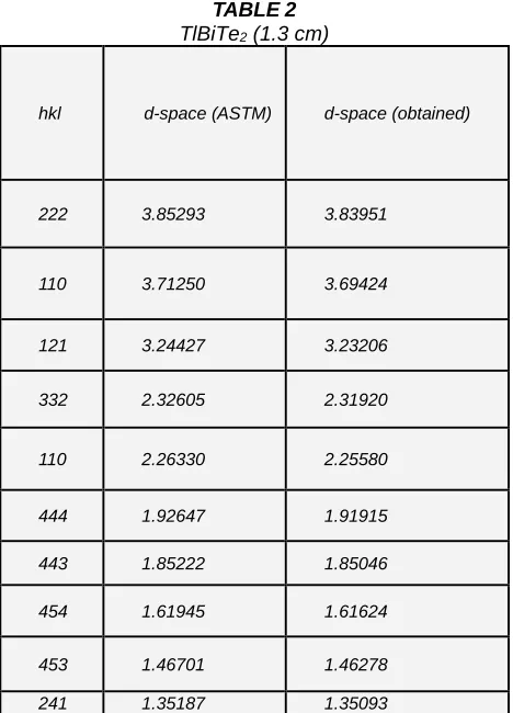
Where d represents the distance between the spaces h, k and l are Miller's indices and a , c are the lattice parameters. In table (1) and table (2) a comparison between the interplanar spaces obtained from the X-ray work and that recorded in the ASTM card is illustrated. All the reflections in the reference TlBiTe2 samples are appeared in the prepared crystals. The interplanar spacing d (Å) values were calculated for the reflecting planes and are listed in the tables. The obtained d-space values are in a good agreement to these recorded in the universal card.
Using the Bragg’s law: n λ = 2 d sin θ is important but applying the induction function F (θ) gives the unit cell a, c far from experimental errors.
This was done for measuring the exact lattice constants (a) and (c) for the two samples by plotting a and F (θ) as shown in
Fig.(5) and Fig.(6).This was based on the following equation:-
2cos
2sin
cos
)
(
=
+
F
It must be mentioned that the obtained average values of the lattice parameters of the samples S1 are (a = 8.77285 nm, c = 2.83 nm) and for S2 are (a = 4.51608 nm, c = 23.05 nm) . This is in accordance to the lattice parameters of the rhombohedral TlBiTe2 reported in the ASTM card (12). Figs. 5, 6 show the relation between the lattice parameters a and c vs.F (θ). The interception of the extrapolation of the straight line with y-axis gives the value of the lattice parameters a, and c accurately.
(
)
(
)
(
)
(
)
3 2 2 2 2 2 2 2 2cos
2
cos
3
1
cos
cos
2
sin
1
+
−
−
+
+
+
+
+
=
h
k
l
hk
kl
hl
d
TABLE 1 TlBiTe2 (1.5 cm)
hkl d-space
( ASTM) d-space (obtained)
104 3.223000 3.23813
018 2.32000 2.32193
110 2.26000 2.25804
111 1.85000 1.84959
208 1.62000 1.61771
112 1.46000 1.46294
211 1.43000 1.43161
TABLE2
TlBiTe2 (1.3 cm)
hkl d-space (ASTM) d-space (obtained)
222 3.85293 3.83951
110 3.71250 3.69424
121 3.24427 3.23206
332 2.32605 2.31920
110 2.26330 2.25580
444 1.92647 1.91915
443 1.85222 1.85046
454 1.61945 1.61624
453 1.46701 1.46278
3.3.2Determination of Grain Size and Micro-strain
Two well-known methods are used for determination the grain size and the micro-strain. This was reported as follows:-
a)
Scherrer's Method(18,19)The Scherrer's crystallite size as measured from the XRD data
for the two samples S1and S2 respectively
areDvol =46.1853 nm,42.33469 nm and
nm 31.75102 nm,
34.63898 =
v ol
L . This was based on
Equation:-
cos
94
.
0
)
(
vol
L
=
Substituting the value of Γ (the full width at half maximum) and the value of θ , we can get Lvol (column lengths). Column lengths that are obtained mainly for groups of molecules can be converted into average grain size if the group of crystals has the same shape in the sample. Spherical shape is usually a standard assumption, then:
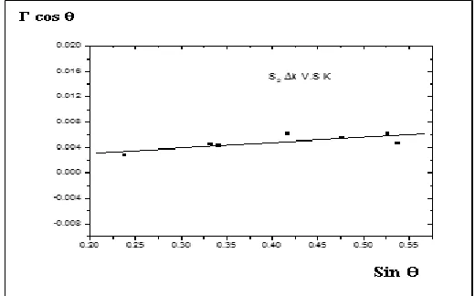
b) Williamson-Hall Method(20,21)
The Scherer formula, although approximate, has been found to be inversely proportional to the size of the unit cell with the values of Dvol and thus Lvol. The Williamson Hall equation can also be obtained as follows:
cos=0.94+4sin
vol
D
Where is the micro-strain. It is known that Williamson- Hall equation takes into account that the total width of the x-ray diffraction peak is i.e. size and strain effects. For the separation, the different dependence is helpful: finding proportional to cos-1 with the size broadening and proportional to tan with the strain broadening. Accordingly if one plot the relation between Γ cos and sin , we can get the value of Dvol from the intercept and from the slope we can
4094 T
he increment of Γ cos with sin indicates the presence of some kind of lattice distortions, however, the deviation from the linear correlation corresponds to the anisotropy.
Now the average dislocation density Re can be determined
from the following equation [22]:-
2=
(
Ab
2/
2
)
R
eC
Where (b2/2) is the Burgers vector, A is a constant defined as the effective outer cut-off radius of dislocations (ρ) and C is the contrast factor. The results of the microstrain and the dislocation density are listed in the previous table.
From the dislocation density relations, the average distance between the adjacent dislocations LC (as appeared in the previous table) can be checked simply as
L
c=
1
/
4. DISCUSSION OF THE RESULTS
Now it is clear that TlBiTe2 is a sensitive semiconductor for the growth conditions .This is evident where the results revealed that ampoule diameter is a governing factor. This diameter is only changed from 13 mm to 15mm. However results are surprising. The crystal S1 is much better than S2 according to the following remarks: The crystal quality is high because
- The sharpness of the main peak is much noticeable in case of crystal SI.
-The height of the main peak is much higher in case of crystal SI.
- It is an established fact that if the main peak intensity is high and it is sharp enough, this indicates a high quality crystal. (see figures 1,2).
- The ratio c/a (which is a function of the tetragonaliiy) is much higher in case of S1.
- The SAM images revealed a better surface in case of S1. (see figure (3,4).
- The increment of Γ cos with sin in case of S2 more than S1indicates the presence of some kind of lattice distortions higher in S2.
- When we used the data of c and a, to calculate the unit cell volume we found that the size is larger in case of S1. - Both Dvol and hence Lvo are much greater in case of S1. - Regarding to table 3 , it is clear that the dislocation density
in the sample S1 is less than in the crystal S2. It is becoming clear that using ampoule with a diameter 15mm yields a better crystal quality. In our opinion we argue this to the Marangoni effect which is based on the thermal gradient. In this respect the origin of the thermal gradient is due to the non-equal distances between the heat source (the furnace) and the points on the liquid surface in each ampoule (note that we used two ampoules with two different diameters). The following Fig. is helpful where it is easy to T1 ›T 2 › T3
TABLE 3
Quantity Values for S1 Values for S2
vol
D
119.6364 nm 94.61438 nmvol
L
89.72727 nm 70.96078 nm
0.0022375 nm 0.00204 nmThen thermal gradient cause surface tension variations. Surface tension gradients must be balanced by viscous shear stresses on either sides of the surface. Generally this is the reason of migration of the droplets and bubbles in temperature gradients. In this way, we can sum up this situation as follows:-
Thermal gradient →surface tension gradient → imbalance of forces → viscous shear stresses → motion in surface molecules → bubble formation or defects.
During achievement of this experiment, the other growth parameters were held constant. This includes the freezing rate.
5.CONCLUSION
As for the present work we have concluded the following definite points:
- The compound TlBiTe2 is an interesting and promising semiconductor.
- We grew two crystals with the aid of two different ampoule diameters in the present paper.
- A lot of investigations were done bearing in mind to compare between the two grown crystals' qualities.
- Among those investigations: X – ray line profile analysis which was applied to obtain structural parameters (crystal lattice, grain size, micro-strain, dislocation density, dislocation arrangement, and the distance between two dislocations).
- Williamson – Hall plot, and Warren - Averbach methods were applied to reveal more details about the crystal structure of the product crystals.
- Also the surfaces of the two grown crystals were analyzed by scanning electron microscopy.
- Throughout the pre-mentioned investigations we concluded that the crystals' qualities are different.
- All results showed that the n-type TlBiTe2 is a very sensitive semiconductor the growth conditions especially the ampoule diameter. In this respect the differences between the crystals were summarized in a very useful table within the text.
- The difference in the crystals' qualities were argued and explained in the framework of the Marangoni effect. - The present work opened up a new investigations according
to that appeared in the plan for the future work stated at the
- It is recommended to find out to which extent the effect of ampoule diameters is dominant? More ampoule diameters are needed to answer this question.
- Can we generalize the present result to other semiconductors? More work is needed to investigate this effect in other semiconductors.
7. REFERENCES
[1] J Paraskevopoulos,. K. M. , J. Phys. C: Solid State Phys., 18 (1985).
[2] Akhmedovs, F. I., Sorokina, I. G., Russin. phys.J., 11: (11) (1968).
[3] Coquillat, D., Pradel, A. and others, phys. stat. sol. (a), 82 (1984) 295.
[4] yulin., C, and Liu, Z.,
http://arxiv.org/pdf/1006.3843.pdf ( 2010).
[5] Polychroniadis,E. K., Stoemenos, J., J. of Crystal Growth, 55 (1981) 388-391.
[6] Popovich, N. S., Shura, V. K. and Gitsu., D. V. Jour.O. Cryst., 61, Issue 2, March, (1983), 406–408.
[7] Kurosaki, K., Kosuga, A., J. Alloys Comp., 351 (2003) 279–282.
[8] Ebnalwaled, A. A., Gamal, G. A., ELshaikh, H. A., & Mahasen, M. M. Journal of Applied Physical Science International (2015). 5(1), 1-8.
[9] G. A. Gamal, A.El-Taher and A.A. Ebnalwaled , International Journal of Scientific & Engineering Research –IJSER, Volume 8, Issue 4, April-2017 page1279
[10]G. A. Gamal , F. A. Al-Mufadi , Salah M. M. Salman, Hussein Zein, Journal of Scientific Engineering and Research, Volume 6 Issue 7, July 2018,103-109 [11]Winter, M.; Brodd, R. J., Chem. Rev, 104 (2004) 4245. [12]Rowe, D. M., In Thermoelectrics Handbook: Macro to Nano; Ed, CRC Press: Boca Raton, FL, (2006) 1-2.
[13]Nolas, G. S.; Sharp, J.; Goldsmid, H. J., In Thermoelectircs, Basic Principlesand New Materials Developments; Springer: Verlag, Berlin, Heidelberg, (2001) 5.
[14]Nolas, G. S.; Sharp, J.; Goldsmid, H. J., In Thermoelectircs, Basic Principles and New Materials Developments; Springer: Verlag, Berlin, Heidelberg, (2001) 12-13.
[15]Natl.Bur.Stand. 539, U.S., Circular, 6 ( 1956) 30. [16]Isenberg, Russell, B. R and Greene, R. F, Improved
Method for Measuring Hall Coefficient, Rev. Sci., 19, 685 (1918).
[17]T.A. Taha, A.A. Azab, M.A. Sebak, Glycerol-assisted sol-gel synthesis, optical, and magnetic properties of NiFe2O4 nanoparticles. J. Mol. Struct. 1181, 14–18 (2019)
[18]Paul., B, Simon Jacques & Martin Vickers., Crystallite
Size and Strain.
http://pd.chem.ucl.ac.uk/pdnn/peaks/size.htm. [Online] (2006).
[19]Scherrer., P.,Gottinger Nachrichten, (1918) 98. [20]Hall.,W.H.. Williamson, G.K., Acta Metall, (1953) 22. [21]Martin, J. D., A software Package for Powder x-ray
4096 from broadened X-ray diffraction profiles”, Physica