59
A Survey On Physical Methods For Deformation
Modeling
Huda BasloomAbstract: Much effort has been dedicated to achieving realism in the simulation of deformable objects such as cloth, hair, rubber, sea water, smoke and human soft tissue in surgical simulation. However, the deformable object in these simulations will exhibit physically correct behaviors true to the behavior of real objects when any force is applied to it, and sometimes this requires real-time simulation. No matter how complex the geometry is, real-time simulation is still required in some applications. Surgery simulation is an example of the need for real-time simulation. This situation has attracted the attention of a wide community of researchers such as computer scientists, mechanical engineers, biomechanics and computational geometers. This paper presents a review of the existing techniques for modeling deformable objects which have been developed within the last three decades for different computer graphics interactive applications.
Index Terms: Real-time simulation, Deformation modeling, Finite Element Method, Soft tissue modeling, Physical models, soft tissue modeling, surgery simulation.
————————————————————
1
I
NTRODUCTIONThe simulation of deformable objects is essential for many applications. For example, computer aided design uses deformable models to simulate the deformation of industrial materials. In image analysis, deformable models are used for boundary smoothing, registration and image segmentation. Later, deformable models have been used in realistic simulations of skin, clothing and for animating human or animal characters in games. Moreover, the modeling of deformable soft tissue is of great interest for a wide range of medical imaging applications, where a realistic interaction with virtual objects is required. The model used for constructing objects with deformable behavior is known as the deformable model. Many methods have been developed for model deformation, which can be categorized as non-physical based methods and physical based methods [1]. Non-physical methods are usually based on pure geometric techniques or the use of simplified physical principles to achieve the simulation of reality. Splines technique like Bezier-curves, B-splines, and NURBS (Non-Uniform rational B-Splines) use sets of control points – called landmarks – to represent 3D curves and surfaces [2]. Another example is FFD (Free-Form Deformation), which deforms the shape of an object by deforming the space in which it is embedded. In applications demanding of the realistic simulation of deformable bodies, there is no alternative to consistent physical modelling. Numerically, it solves PDEs (Partial Differential Equations) of elasticity theory, but PDEs are also used to formulate problems involving functions of several variables, such as the propagation of sound or heat, electrostatics, electrodynamics, fluid flow and elasticity. There are many different methodologies for solving systems of PDEs. The most widely used methods for physical based modeling of deformable objects are: MSD (Mass-Spring-Damper) systems, the BEM (Boundary Element Method), the FDM (Finite Difference Method), FVM (Finite Volume Method) and the FEM (Finite Element Method) [1].
This paper deals with physical models which use the numerical method for solving PDE such as MSD (Mass-Spring-Damper) systems, the BEM (Boundary Element Method), the FDM (Finite Difference Method), FVM (Finite Volume Method) and the FEM (Finite Element Method). This paper will analyze each of the mentioned methods briefly, and will emphasize concerning the use of the FEM.
2
B
ACKGROUND2.1 Deformation
Deformation is a general term that includes all changes in the shape or volume of a deformable object. However, the deformable object is an object combined with the material properties which define how the object will deform under any applied force. The applied force could be pressure, external load, body force, temperature change or any other force. The material could be metal, plastic, rubber, soft tissue of the human body or any other material.
There are two types of deformation:
Elastic deformation: the deformation is reversible in this type – that is it is not permanent - in that the deformation will recover, and the object will return to its original shape and size after the applied force has been released. Plastic deformation: this type of deformation is irreversible, in that the object will not return to its original shape, even after the force is no longer being applied.
____________________________
Deformation is measured by strain (see equation 2.1), whereby strain is a measure of the changes in length, volume and shape in a stressed material. Deformation is synonymous with strain [3].
𝜀 = 𝑑𝑙 𝑙 ⁄ = 𝜎 𝐸⁄ (1)
Where:
𝑑𝑙 is the change of length (m) 𝑙 is the initial length (m) 𝜀 is the strain
𝐸 is the Young's modulus (Pa)
From equation 1, we find that the deformation is a function of displacement, where it represents the displacement between particles in the deformed body. However, the shape of the body is determined by the distances between nearby particles. As the body deforms, these distances change. The stress is a measure of the magnitude and direction of a deforming force (see equation 2). Stress is used rather than pressure because stress includes the concept of direction [3].
𝜎 = 𝐹 𝐴⁄ (2)
Where:
𝜎 is the stress ((Pascal)or N/𝑚 ) 𝐹 is the applied force (Newton) 𝐴 is the area (𝑚 )
2.2 Deformable model
The deformable model is used for constructing objects displaying deformable behavior. Generally, the existing modeling techniques can be arranged into two major categories: physical models and non-physical models. The physical models are based on solving continuum mechanics problems under consideration of material properties and other environmental constraints. All other modeling techniques, even if they are related to mathematical physics, are known as non-physical models [4].
3
N
ON-
PHYSICAL MODELSNon-physical methods are usually based on pure heuristic geometric techniques, where individual or groups of control points or shape parameters are manually adjusted for shape editing and design purposes. These techniques are very popular in computer graphics and sometimes are used in real time applications, since they are computationally efficient in comparison with expensive physical approaches. The output relies on the designer's skills. Accuracy is not guaranteed in this approach because of the ignorance of physical properties. Splines techniques [5], like Bezier-curves, B-splines and NURBS use set of control points - called landmarks -to represent 3D curves and surfaces. The main idea of spline is to modify the shape of complex objects by varying the position of few control points. Also, the number of landmarks, as well as their weights, can be used for adjustment of the object deformation (see Error! Reference source not found.). [1] In 1986, Sederberg [6] developed FFD technique, where the shape of an object is changed by deforming the space in which the object lies. This technique can be applied to many different graphical representations, including: points, polygons, splines, parametric patches, and implicit surfaces. The basic FFD method has been extended by several others [6, 5].
4
P
HYSICAL MODELSPhysical based modeling uses physical principles and computational power to model realistic behaviour of deformable models that would be difficult or impossible to model with purely geometric techniques. However, the results are more convincing than the non-physical based methods. In the applications, which demand the realistic simulation of deformable physical bodies, there is no alternative from using physical modeling which solves the PDE (Partial Differential Equation) of elasticity theory. PDEs are used to formulate problems involving functions of several variables; such as the propagation of sound or heat, electrostatics, electrodynamics, fluid flow, and elasticity. There are many different methodologies for solving system of PDEs. The most widely used methods for physically based modeling of deformable objects are: the MSD systems, the FVM, the FDM, the BEM and the FEM.
4.1 Mass-Spring-Damper
Mass-spring systems have been used widely and effectively for modeling deformable objects. The object under consideration is represented by a set of mass-points connected by springs in a lattice structure (see Figure 2). It is the simplest computational method. However, MSD was the first model to be applied to the field of surgery simulation. In 1993, Cover and Ezquerra [2] presented the first real-time models for surgery simulation. They used a simple surface-based mass-spring model to simulate the deformation of a gall bladder. They produced a prototype system that lets the user interactively manipulate models of the gall bladder and its surrounding organs.
Figure 2 A portion of a mass-spring model. Springs connecting point masses. [1]
61 4.2 Finite Difference Method
The FDM is the oldest of the methods for numerical solution for the PDE. It subdivides the domain into small discrete segments separated by nodal points where the unknown variable –for example, fluid flow domain- is defined only on these nodal points. The most attractive feature of this method is that it is very easy to implement.
Figure 3 Persian carpet falling over immobile obstacles [7].
In the late Eighties, Terzopoulos et al. proposed the use of physical models for animating elastic and plastic objects [7] and fracture effects which pioneered the use of physically-based models in the field of computer graphics (see Error! Reference source not found.). They used surfaces to represent deformable objects and solved the governing partial differential equations using finite difference schemes. They focused on the correct modeling of physical effects, but the speed of the simulation was of secondary importance and computations were done offline. The first point to make about the FDM is that it is best suited to problems that have relatively simple geometries. However, the discretization of objects with irregular geometry is not accurate using this method [7]. The quality of a FEM approximation is often higher than in the corresponding FDM as shown in Error! Reference source not found.. The other methods presented in this section are often more efficient than the FDM.
Figure 1 Domain discretization. Left: FEM, right: FDM[7]
4.3 Finite Element Method
FEM is a state-of-the-art technique in physical modeling and simulation. It is superior to all methods when accurate solutions of continuum mechanics problems with complex geometry have to be found. "It also provides the most flexible modeling platform free of all limitations with respect to the material type and the boundary conditions" [4]. The FEM divides the object into a set of elements which could be tetrahedrons or hexahedrons (see Error! Reference source not found.). It is an effective technique for solving elasticity problems. The most attractive feature of the FEM is its ability to handle complicated geometries (and boundaries) –which make it sounder -with relative ease [8]. Moreover, it is widely used in the simulation of virtual surgery since it can model elasticity behavior of soft tissues accurately. Generally, FEM is the method of choice in all types of analysis in structural mechanics (i.e. solving for deformation and stresses in solid bodies or in the dynamics of structures) while CFD (Computational Fluid Dynamics) tends to use the FDM or the FVM.
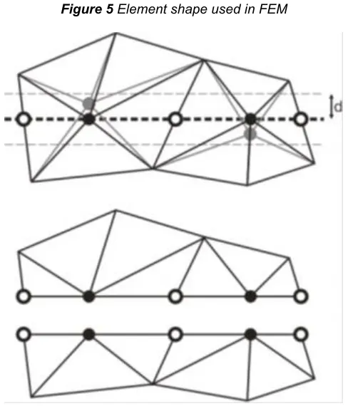
Figure 5 Element shape used in FEM
Figure 2 New cut node and cutting path [18].
performance of the FEM is not satisfactory because of the computational time [4]. Much research has been done into improving the time required in simulating deformation, and now we are approaching the possibility of reach real-time deformation. Cotin and Delingette (1998) [9] presented three physical models based on linear elasticity theory and finite elements modeling. The first model pre-computed the deformations and forces applied on a FEM, therefore allowed the deformation of large structures in real-time. The second physical model is the tensor-mass model- it was analogous to MSD -, which allowed simulating cutting and tearing. This model allowed volumetric deformations and cuttings but it is slower and less stable. In the third model, they combined those two approaches into a hybrid model to take the advantages of real time deformations and cuttings of large enough anatomical structures. BroNielsen and Cotin (2001) [10] introduced three ways to speed up the FEM with their algorithm. They inverted the system matrix and used matrix vector multiplication with this matrix. This improvement led to the achievement of very low calculation time. They then used condensation which compressed the system matrix, and resulted in a system with the complexity of surface model but the behavior of a volumetric model. Muller and Gross (2004) [11] extended the warped stiffness finite element approach for linear elasticity and combined it with a strain-state-based plasticity model. They proposed an algorithm to consistently animate and fracture a high resolution surface mesh based on a coarser underlying volumetric mesh. This multi-resolution strategy produces realistic animations of a wide spectrum of materials, and enables the simulation of geometrically complex objects in real time. Garcia and Robles (2008) [12] presented a technique called MSRS (Matrix System Reduction Solver) which accelerates the real-time simulation of deformable objects using FEM. An initial solution is first computed combining a precalculated solver and the global mesh rotation then, the nodes that show large errors are solved separately, using a matrix smaller than the whole system matrix. The initial solution given by the system is sufficient when the object has small deformations. When the object is highly deformed, extra time is needed. This extra time depends on the magnitude of the deformation. An improved version of the prior cutting methods, based on Stiffness-Warped FEM, which perfectly utilised, in real-time virtual surgery applications, was presented by Cakir and Yazici (2009) [12].The prior cutting algorithm is based on determination of cut nodes and cut edges. If the distance between cutting surface and a node is smaller than threshold d, this node is selected as a cut node and duplicated. Otherwise, the cutting surface splits the cut edge into two new edges. The improved version selects the average point of two intersection points close to the cut node. Thus, cut nodes are translated into the cutting path to avoid the degeneration of the original path. This is illustrated in Figure 6. This cutting simulation framework depicts the behaviour of soft tissue, realistically. Namima and Wang (2009) [13] developed a new model to simulate the grasping and rolling motion between two soft fingers and an object (see Figure 7and Figure 8) Using FEM and CSM (Constraint Stabilisation Methods), they were able to simulate the stable complex motions of human fingertips, which has complex structure.
Figure 7 Simulation of grasping and rotating an object. Left: grasping object, right: rotating object.[13]
Figure 8 Human index finger meshing [13]
Dick and Georgii (2010) [14] presented a multi-grid approach for simulating elastic deformable objects in real time on recent NVIDIA GPU (Graphics Processing Units) architectures (see Error! Reference source not found.). Their method is based on an FEM discretization of the deformable object using hexahedra. They exploit the GPU’s parallel processing units and high memory bandwidth via the CUDA (Computer Unified Device Architecture) parallel programming API (Application Programming Interface). The CUDA API is used because, in contrast to graphics APIs like OpenGL or Direct3D, it gives the programmer direct control over all available computing and memory resources. The performance gains up to a factor of 27 and 4, compared to a highly optimised CPU implementation on a single CPU core and 8 CPU cores, respectively.
63 4.4 Finite Volume Method
FVM is an alternative way for approximating the solutions to differential equations. This method discretizes the domain into a finite number of non-overlapping control volumes. At the centroid of each of the control volumes, the transport variables values are calculated and stored. Since the spars matrix of the resulting algebraic equations is always diagonally-dominated [8], the FVM is generally faster than the FEM in a three dimensional simulation. It is widely used in fluid dynamics, but rarely used in human body deformation. Teran and Sifakis (2005) [15], presented a framework for extracting and simulating high resolution musculoskeletal geometry from the segmented visible human data set using the FVM (Error! Reference source not found.). They simulated 30 collision coupled muscles in the upper limb. The presented framework allowed for the creation of highly detailed geometry as well as for realistic anisotropies and heterogeneities. Unfortunately, the computational time was very great.
Figure 10 Musculoskeletal model created from the visible human data set. Tendons are shown in pink. There are about
10 million [15]
4.5 Boundary Element Method
The BEM is a straight-forward approach to discretizing the boundary of an object into a set of N non-overlapping elements. It requires less time for the solution of a problem than other methods due to the small system of the equation, because the process of discretization takes place only on the surface of a body. Consequently, the system of equations is much smaller. Such a technique could achieve real-time simulation since the discretization is only on the surface, which is why it is not costly. [13] An example of the application of the BEM for the modeling of deformable objects is given in [13], where James and Pai (1999) designed the first system to simulate elastic objects at interactive rates (see Error! Reference source not found.). They use a linear BEM with pre-computed modes for a fixed geometry. BEM has not been successfully applied to non-linear fluid flow problems and the mathematics used in the BEM is unfamiliar to the engineering community, so they are not interested in such mathematics. Moreover, the system matrix when using the BEM is fully occupied which makes the application of efficient iterative solving techniques difficult or even impossible [4]. Non-homogeneous materials cannot be modeled by the BEM and it is not suitable for soft tissue modeling [4].
Figure 11 An example of using BEM. Left: initial state, right: after force applied. [13]
5
C
ONCLUSIONFEM is the widely used method in physical modeling and simulation especially for human body deformation and surgery simulation. It is superior to all methods when an accurate solution with regard to irregular geometry has to be found. Real-time deformation has now been achieved through a great deal of research and by using recent NVIDIA GPU. The new technology and speeds of memory also helps. The MSD model is the simplest computationally. Therefore it was widely used in real time applications such as surgery simulation but it does not allow accurate modeling of material properties. In addition, the accuracy of modeling is poor. Both the FDM and the FVM, widely used in CFD, are rarely used in modeling human body deformation. FDM achieves efficiency and accuracy when the geometry of the problem is regular, but discretization becomes extremely dense when approximating the boundary of an irregular object. The FEM is superior to the FDM when handling geometric approximation. The BEM has very long history in engineering analysis applications. However, it is not widely used in computer graphics for simulating deformable objects. It considers the boundary of the object only, which makes it faster but less accurate than FEM. The following table summarize the comparison between all methods:
As a result of this literature review, the FEM is widely used because of its accuracy when it comes to simulating the real interaction with the human tissue. The measure of deformation which has occurred in the liver according to the patient's record will help the doctor to take the right decision, and will support him by the information which will result due to the application of a specific applied load.
References
[1] Mirtich, S.F.F.G.B., A Survey of Deformable Modeling in Computer Graphics, in A Mitsubishi Electric Research Laboratory. 1997, MERL.
[2] Cover, S.A., et al., Interactively deformable models for surgery simulation. Computer Graphics and Applications, IEEE, 1993. 13(6): p. 68-75.
[3] Wulpi, D.J., Understanding how components fail, ed. 1. 1985, Metals Park, Ohio: American Society for Metals. 39-42.
[4] Manohar, V., et al. Modeling Facial Skin Motion Properties in Video and Its Application to Matching Faces across Expressions. in Pattern Recognition (ICPR), 2010 20th International Conference on.
[5] Yu-Kuang, C. and P.R. Alyn, A generalized de Casteljau approach to 3D free-form deformation, in Proceedings of the 21st annual conference on Computer graphics and interactive techniques. 1994, ACM.
[6] Sabine, C., Extended free-form deformation: a sculpturing tool for 3D geometric modeling. SIGGRAPH Comput. Graph., 1990. 24(4): p. 187-196.
[7] Demetri, T., et al., Elastically deformable models, in Proceedings of the 14th annual conference on Computer graphics and interactive techniques. 1987, ACM.
[8] Huang Maosong, Y.X., Huang Yu, Soil dynamics and earthquake engineering. 2010, Shanghai, China: American Society of Civil Engineers
[9] Delingette, H., S. Cotin, and N. Ayache, Efficient linear elastic models of soft tissues for real-time surgery simulation. Vol. 62. 1999. 100-1.
[10] M. Bro-Nielsen, S.C., Real-time volumetric deformable models for surgery simulation using finite elements and condensation, in Computer Graphics Forum. 1996: University of Denmark.
[11] Matthias, M., ller, and G. Markus, Interactive virtual materials, in Proceedings of Graphics Interface 2004. 2004, Canadian Human-Computer Communications Society: London, Ontario, Canada.
[12] Marcos, G., et al., Technical Section: MSRS: A fast linear solver for the real-time simulation of deformable objects. Comput. Graph., 2008. 32(3): p. 293-306.
[13] Kazuki, N., W. Zhongkui, and H. Shinichi, Simulation of soft fingertip deformation under contact and rolling
constraints using FEM and CSM, in Proceedings of the 2009 international conference on Robotics and biomimetics. 2009, IEEE Press: Guilin, China.
[14] Christian Dick, J.G., Rudiger Westermann, A real-time multigrid finite hexahedra method for elasticity simulation using CUDA. 2011. 19(2): p. 801-816.
![Figure 2 A portion of a mass-spring model. Springs connecting point masses. [1]](https://thumb-us.123doks.com/thumbv2/123dok_us/9001812.1437860/2.612.330.561.410.582/figure-portion-spring-model-springs-connecting-point-masses.webp)
![Figure 7 Simulation of grasping and rotating an object. Left: grasping object, right: rotating object.[13]](https://thumb-us.123doks.com/thumbv2/123dok_us/9001812.1437860/4.612.312.573.562.657/figure-simulation-grasping-rotating-object-grasping-object-rotating.webp)
![Figure 11 An example of using BEM. Left: initial state, right: after force applied. [13]](https://thumb-us.123doks.com/thumbv2/123dok_us/9001812.1437860/5.612.315.569.519.726/figure-example-using-left-initial-state-right-applied.webp)
