© 2015 IJSRST | Volume 1 | Issue 5 | Print ISSN: 2395-6011 | Online ISSN: 2395-602X Themed Section: Science and Technology
Permanent Magnetic Theory and Design Methodology of Variable Field Spiral
Efficient Motor
Dr. A. Rashid, Komal Saleem, Dr. Mohsin Amin, Sifat Shah
Electrical Engineering Department. COMSATS Institute of Information Technology, Abbottabad, Pakistan
ABSTRACT
Design methodology of Permanent Magnetic Motion is presented in this work. Experimental proves are given that how magnetic energy is efficiently converted into mechanical energy. The motivation of present research is to develop efficient motor by using available magnetic energy. Spiral Efficient Motor (VFSEM) is a permanent magnetic motor which is more efficient than conventional DC motors because of more than 90% flux linkage. VFSEM possess unique characteristics from typical DC motors. Principle is based on variable stator field and electromagnetic rotor and is accomplished by varying distance; as distance is proportional to field. In the attractive mode the radial magnetic field's strength increases or in repulsive mode strength decreases as the rotor turns through one complete cycle. Variable magnetic field is applied to a finite distance after words it repeats itself hence rotor get locked between minimum and maximum field strength. In order to help the rotor to traverse the gap an electromagnet pulsed switch is used. Mathematical and experimental proof of this theory is mentioned in this work.
Keywords : Permanent Magnet Motor; Variable Filed Motor; Spiral Efficient Motor
I.
INTRODUCTION
Electric motors perform a variety of functions; almost every mechanical movement that we see around us is accomplished by an electric motor. Electric motors are used at almost every industry in production of nearly every admissible product. In addition to running a very large portion of manufacturing processes electric motors are extensively used in daily use common place appliances. Electric motors are used as a means of converting energy usually electrical energy to mechanical energy. Almost 70% of power is consumed by these motors, Conventional motors efficiency is estimated up to 80%.
Taking in account the surge in power demand and continuous energy consumption growth due to inductive load authors felt in need of energy efficient motors. Increasing the efficiency will decrease the power consumption of motors. The basic ambition of this research is just to develop an energy efficient motor. Energy free motors [6] are practically impracticable and violate the law of thermodynamics. Motors actually involve conversion of energy from one form to another,
rather than creation of energy from nothing. Two media concept [1] claimed was somehow practically impossible. Literature shows that instead of two media concept a mechanical push to rotor is exhibited at lock point which contributes to mechanical losses [1]. Electromechanical push draws fewer losses than giving a mechanical push explained in this paper. An electrical pulse is used to unlock the rotor.
Magnets do have indeed energy stored in them and also distinctive property of attraction or repulsion between magnets, and also from some materials called ferromagnetic [12]. By employing this property of magnets such an arrangement was made in which motion befalls due to force of attraction of magnets. Basic principal of VFSEM is that, it uses the force of attraction of magnets and rotates.
point (lock point). If we use permanent magnets on both rotor and stator problem is faced in unlocking, that's why electromagnetic rotor is preferred.
For the economical implementation of the theory, we made a discrete length of variable magnetic field (can be increasing or decreasing) and electromagnetic rotor with more than 90% of flux linkage. Magnetic field is extended to a finite distance after which it repeats itself. At point of repetition rotor get locked. In order to detent rotor at lock point, demagnetize rotor through a proximity sensor and let it move under inertia and magnetize it again when reaches the area of minimum flux density.
II.
METHODS AND MATERIAL
Literature Review
With the invention of the battery (Allessandro Volta, 1800), the generation of a magnetic field from electric current (Hans Christian Oersted, 1820) and the electromagnet (William Sturgeon, 1825) the foundation for building electric motors
was started. The first rotating device driven by
electromagnetism was built by the Englishman Peter Barlow [10] in 1822 (Barlow's Wheel). After many other more or less successful attempts with relatively weak rotating and reciprocating apparatus the German speaking Prussian Moritz Jacobi [11] created the first real rotating electric motor in May 1834 that actually developed a remarkable mechanical output power.
After the invention of different motors scientists
put their heads together to create a motor with remarkable efficiency. The Stern Gerlach [2] performed an experiment in 1921 on an inhomogeneous magnetic field. In his experiment the magnetic field is stronger at one end of the track weaker at the other end same as that of our case, whether the inhomogeneous magnetic field is linear or circular. The equation of gradient force is
dz dB Fz scos
Inhomogeneous magnetic field
creates the circumferential force. A net deflecting force exerted on each magnetic moment is μs.
Hartman [3] in Dec 1977 uses the variable field of permanent magnets to move a steel ball upward along a 10 degree inclined plane. This shows that linearly we can claim concept is energy free. According to Volone's Rule electric input
energy or its substitute is always necessary with a basic Archimedean spiral magnetic motor (field varies with distance).
Japanese Firm of Kure Tekkoshi in 1970's secured a number of Japanese patent towards spiral set of magnetic motors with name Magnetic Wankel Motor. In June 1970 Scott David [4] invent Magnetic Wankel motor by using permanent ferrite magnets in stator and give electrical pulse to unlock rotor but because of weak coercive force of ferrite magnets Magnetic Wankel was not a successful attempt as self-powered motor. Paul Monous [5] in 1982 inspired by Japanese firm of Kure Tekkosho build another Magnetic Wankel Motor which turn to 1400 rpm and uses only 80 mW. Historically an electromagnetic pulsed mechanical switching has been used to assist the rotor to traverse the gap in between the end and start of the magnetic stator (Kure Tekko, 1980)
Later energy free Permanent Magnetic Motor was invented by Johnson Howard [6] in 1979 and J. Lawon [7] in 1986. Due to complicated design these motors ware difficult to engineer. Motors have also defect to get locked at many points on load.
Latest in year 2012 A. Rashid [1] proposed a motor Variable
Field Permanent magnetic motor they practice an
electromechanical actuator to unlock. It has variable field rotor and a magnetic mounted on actuator as stator, Switching arrangement is used to give a mechanical push to unlock rotor but their motor have mechanical losses and they presented 2 media concept which is practically impossible. Despite of all above mentioned researches it is obvious that free energy motors are practically impossible. Inhomogeneous magnetic field motors also have some defects and complicated construction. Cost effective and highly efficient motors are needed now days for ease and compatibility. For this we are working on VFSEM.
Proposed Design
Before indulging to core concept of this motor let we summarize the innovation. Variable Field Spiral Efficient Motor (VFSEM) can be exercised both as linearly and circulatory. VFSEM does not only provide rotational energy for useful work, its linearly concept also helps in moving weight upward on an inclined path, for drilling purpose, in guns, as mass conveyor etc.
researches. South Pole of fixed magnet is downward as shown in figure (1).
III.
RESULT AND DISCUSSION
Figure (1): Movement of movable magnet towards fixed magnet
Figure (2): Movement of movable magnet towards fixed magnet
Figure (3): Movement of movable magnet towards fixed magnet
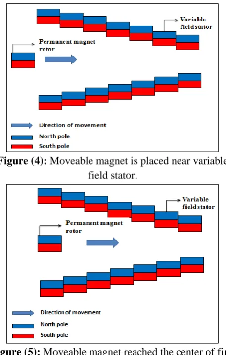
Figure (4): Moveable magnet is placed near variable field stator.
Figure (5): Moveable magnet reached the center of first slot of stator.
Figure (6): Rotor continuous its motion till it reaches at the center of last slot of Rotor
2.1 Linear Concept
towards each other. Let North Pole of moveable magnet B is upward and South Pole of fixed magnet is downward as shown in figure (1).
If movable magnet is fixed on rail and is only allowed to move in X-axis direction rightwards then due to the force of attraction between these two magnets, magnet B moves towards magnet A as shown in figure (2). Magnet stops when reaches below the fixed magnet .For continuous motion, the increase the magnetic field of fixed magnet by decreasing the distance of every next slot. Increasing field with decreasing distance is shown below in figure (3).
Minimizing the distance between two bar magnets increases the flux lines which contributes in increase of magnetic field density „B‟. By using the above concept we design a linear model of variable field Spiral Efficient motor (VFSEM) shown in figure (4).
Each magnet of stator is termed as a slot. Moveable magnet (rotor) moves due to the change of magnetic field. Rotor always experiences a forward force because of increase in magnetic field due to decrease in distance. Rotor moves towards first slot as shown below in figure (5). This motion continuous till last slot after which rotor stop experiencing any forward force. Infinitely increase in field gives infinite Rotor's motion as shown in figure (6).
If stator field increase infinitely than rotor will continuous to move forever without any input source. But practically it is impossible; rotor will stop at the last magnet which is named as lock point. In order to unlock the rotor electrical pulse is provided. As per Coulomb's law:
We have two isolated North Pole magnets, m1 and m2 are strengths (intensity) of magnets and r is the distance between them as shown in figure (7).
Figure (7) : 'm1' and 'm2' are strength of magnets
separated by distance 'r'
Mathematically it is stated as
Where K is the constant of proportionality and is equal to
4
hence
(1)
Equation (1) shows the inverse relation between the distance and force of attraction between two isolated magnets.
Graphical representation of Coulomb's law is shown in following Figure (8).
Figure (8): Graphical representation of coulomb's law for linear motor.
Graph shows that Force decreases exponentially as distance increases. Force increases as strength of magnets increases, similarly force increases as the distance decreases. An inverse relation is seen between Force and distance. We can create variable field by changing the distance to increase force of attraction between magnets as shown in the graph.
2.3 Construction
Locking of rotor at lock point is shown in figure (10). Rotor gets lock because it experiences no forward force which results in locking of Rotor.
In order to unlock the rotor, an electromagnetic rotor has been employed instead of a permanent magnet Rotor. Power supply is disconnected at lock point and let the rotor move under its own inertia without any force of attraction or repulsion of magnets. When rotor again reached first slot (first magnet) supply is reconnected. Rotor again start experiencing a forward force and continuous its motion. Each time at lock point supply is disconnected. An electromagnetic type Rotor motor is shown in figure (11).
To magnetize and demagnetize the rotor at lock point and for the determination of continuous motion Proximity sensor has been used as shown in figure (12), which detects metals magnets etc. At lock point it disconnects the circuit by detecting a metallic strip placed at lock point.
Figure (9): Practical arrangement of circular motor.
Figure (10): Lock point of motor.
Figure (11): Electromagnetic Stator and permanent magnet Rotor
Figure (12): Proximity sensor
3. VFSEM fundamentals:
The linear concept made in section (4) served as introduction to Variable Field Spiral Efficient Motor (VFSEM). Its behavior closely resembles to conventional DC motor. Variable Field Spiral Efficient Motor has variable field, and conventional DC motor has constant field (flux). The mathematical equations of Variable Field Spiral Efficient Motor are derived.
3.1 VFSEM advance equations:
As magnetic field of VFSEM is not uniform, field varies with distance. Equation below shows that how value of B varies with distance.
n
i
i i i
i r
n i
i
x x x
x B
B
1 2
1 2
1
1 2( 1) 4( 3)
1 tan
) 2 4 ( 2
1 tan
2
x1,x2, ...xnv shows the change in distance between magnet and
material. Considering the average effect of all magnets denoted by Bavg. For convenience B is used instead of Bavg.
E.m.f induced in rotor is
2
1) cos
sin ( )
(v B l vB
l
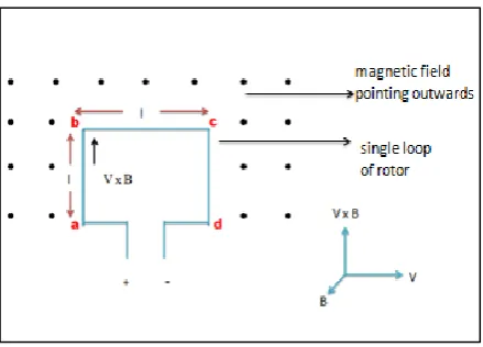
eind Vector explanation of cross sectional view of motor is given below in figure (13).
Figure (13):Cross sectional view of motors and Vector representation of magnetic field density B and velocity V
By analyzing all the angles the final equation which shows the e.m.f induced is twice in whole loop, same is that for torque [9].
da ind cd
ind bc
ind ab
ind
ind
e
e
e
e
e
vBl
vBl
e
ind
vBl
e
ind
2
(3)
Using equations of area'A2rl', velocity
'
v
r
'
and flux '
AB'in equation (3) final equation become.
vind
K
e
(4)
Where
K
vis voltage constant and is equal to
1 .
Thus voltage induced in motor is equal to the product of variable flux and angular velocity of machine. In general voltage induced in VFSEM depends on the following three factors.
1. Variable flux of the motor 2. Angular velocity
3. A constant represents the construction of machine Force on loop shown in figure (13) is
)
(
l
B
i
F
(5)Same as that of e.m.f induced force on loop is also twice. ilB
F2
Torque induced in the motor is
rF 2ilBr (6)
Using the equation of area
'
A
2
rl
'
and flux ''
AB in equation (6) final equation become.i
K
t
(7) WhereKtis torque constant and is equal to
1 same as
that of voltage constant.
Thus torque produced in motor is equal to the product of variable flux and current in the machine. In general torque in VFSEM depends on the following three factors. 1. Variable flux of the motor
2. Current in the machine
3. A constant represents the construction of machine
3.2 Theoretical Efficiency:
Using above derived equations and following practical parameters:
Neodymium magnets have been used whose Br value is
1000. Total number of slots are 8 mean n=8. Every next magnet is 0.3inches nearer than previous one to electromagnetic rotor.
Length of wire l=10 m, input voltage V=30 volts, radius of motor r=0.25 m, resistance of winding R=0.5Ω, current drawn by winding i=5A, mechanical losses Pm=1W, stray losses Ps=1W.
Through calculation the efficiency of VEFEM comes as 90.3% which higher compared with conventional D.C motor.
4. Modeling and simulation of VFSEM:
Applying a voltage V to the coil causes a current i to flow in presence of magnetic field, which according to equation (6) produces a proportional torque, which accelerates the rotor (Newton‟s law). As the rotor gathers speed, a proportional e.m.f is generated, according to equation (3), which tends to oppose the current. Rotor gathers sufficient speed such that the back e.m.f. just equals the applied voltage. In the steady state,
when Va = e.m.f. no current flows in the coil so there is
no further acceleration and the rotor start rotation at a constant speed.
4.1 Modeling of Motor:
Electrical model of motor includes armature resistance, armature inductance, e.m.f. induced and input voltage as shown in figure (14a).Similarly mechanical model of motor includes inertia, torque, damping and load torques shown in figure (14b).
From Figure (14) a, b we can write the following equations based on the Newton‟s law combined with the Kirchhoff‟s law which leads to electrical and mechanical model of VFSEM.
Figure (14): (a) Equivalent electrical model of motor (b)
Equivalent mechanical model of motor
4.1.1 Electrical Model:
Where VR and VL is the voltage across the resistor and
inductor respectively and e is voltage induced in the rotor's coil, which are further equal to
Where i is the armature current, L is the inductance of the rotor coil and Kv is the velocity constant.
Rearranging the equation we get.
L K L iR L V
i v
4.1.2 Mechanical Model:
Where Te is the electromagnetic torque, Tω o
is the torque due to rotational acceleration of the rotor, Tω is the torque produced from the velocity of the rotor, and TL is the torque of the mechanical load torque, which is
further equal to
L
t B T
dt d J i
K
Where Kt is the torque constant, J is the inertia of the rotor and B is the damping coefficient associated with the mechanical rotational system of machine. Rearranging the equations we get.
4.1.3 State Space Model: State Space model of VFSEM is.
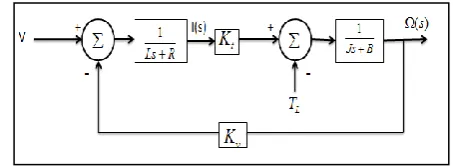
4.1.4 Block Diagram: Final Laplace equations are.
R Ls K V s I v ) ( B Js T s I K
s t L
( ) ( )
The block diagram obtained from these equations for VFSEM is shown in Figure (15).
Figure (15) Block diagram of motor
(8)
L L t v T V i y y T V J L i J B J K L K L R i 0 0 0 0 1 0 0 1 1 0 0 1 2 1 (11)
(10)
J B i J K J T J B i J K J T dt d t L t L L K L iR L V i dtd v
0
T T TL
Te
e
V
V
V
R
L
v K iR V i dt d
4.2 Simulation of VFSEM:
Above equations (10) and (11) are used to simulate the VFSEM as shown in figure (16). Simulation was done in mat lab software. System outputs are shown in figure (17).
Consider the following values for the physical parameters:
moment of inertia of the rotor J =0.05 kgm2
damping (friction) of the mechanical system B=0.01 Nms
flux per unit area Φ=9.42Wb
back electromotive force constant Kv =0.01 Nm/A
motor torque constant Kt =0.01 N.m/Amp
electric resistance R = 1 Ω
electric inductance L = 0.2 H
Figure (16) simulation diagram of motor
Figure (17): Simulation results. Graph 1: motors speed verses time. Graph 2: Current verses time. Graph 3: Input
voltage verses time.
Results of simulation are shown in figure (17), input voltage, current drawn and RPM produced are examined. Motor draws a little higher starting current and then stabilized, motor will run at a constant RPM. A constant input DC voltage produces constant torque.
5. Experimental Proof and Workability:
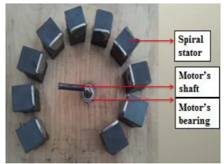
Successful prototype was made which proves the workability of idea and has many practical applications. Pictorial representation of Hardware is shown in figure (19).
As core concept of motor is magnetic field varies with distance as already explained. Variable magnetic field stator of practical motor with respect to distance is shown in figure (18). Because of variable distance stator become spiral.
A DC battery was used to magnetize and demagnetize rotor through Proximity sensor at lock point, as proximity sensor has a property to detect magnets metals etc. Using this property, sensor placed it in front of lock point as shown in figure (19). Proximity sensor is normally closed and used to energize circuitry of rotor through a relay. Whenever rotor reached lock point sensor detects it and give signal to relay which opens the circuit (demagnetize the rotor). When rotor moves forward under inertia, sensor stop detecting any metal hence signals terminated and relay closes the rotor circuit.
Figure (18): Stator having Variable field produced by variable distance.
V
w
i
voltage
speed
current Step
-K-Kt(phi)
1 s Integrator1
1 s Integrator Add1
Add
5 1/L
-K-1/J
-1 -R -K--Kv(phi)
Figure (19) Experimental motor 6. Comparison
Motor explained in our research has more flux linkage than conventional DC motor shown in figure (20). As
dt d N emf
Greater the flux linkage greater will be voltage induced. More than 90% flux linkage found in VFSEM, as shown in blue color in figure (20).
Figure (20): Flux linkage comparison between VFSEM and DC motor. (a) VFSEM. (b) DC motor. Efficiency (93.3%) of VFSEM is also greater than conventional motors, this is because of more flux linkage, no commutation losses, and no carbon brushes as used in conventional motor.
IV.
CONCLUSIONIt has been demonstrated that the VFSEM can develop significant torque and horsepower. It is also encouraging that electrostatic energy density is much lesser than magneto static energy. We can use natural energy stored in magnets than electromagnets. However, to detent the gap, several creative methods have been proposed [1] [4], but method explained in this research is more practical and efficient. It is predicted that future work in this area alone will yield enormous improvements to the point that these kinds of motors can work more efficiently than existing DC motors. With the same
output torque or work done VFSEM consumes less input power as compare to conventional DC motor. It is also obvious that there is no practical application of free energy motors. Some of Inhomogeneous magnetic field motors [4] also have some defects and complicated designs. Cost effective and highly efficient motors are needed now days for ease and compatibility and VFSEM is an alternate.
Further Research
Proper Practical motor is our next motto. This motor will replace the conventional DC motor, and consumes less power for the same work done.
V.
REFERENCES[1] Abdur. R, Kamran Y, Zeeshan A. ‟ Theory of Permanent
Magnetic Motion and Variable Field Permanent Magnetic Motor ˮ,Arabian Journal for Science and Engineering., Dec 2012,pp. 1-11.
[2] Gautreau et al., McGraw H, “Modern Physics”,
Schaumm‟s Outline Series, 1978.
[3] Hartman, Emil T, U.S.Patent 4,215,330‟Permanent
magnet propulsion systemˮ, December.20, 1977.
[4] Scott, David. “Magnetic “Wankel”for electric
cars”,Popular Science, June1979 pp.80-81.
[5] Paul M,BSEE ‟ Magneto-electric machinesˮchap 09,
1982.
[6] Johnson, Howard R.,U.S. Patent 4,151,431 ‟ Permanent
magnet motor ˮ, April.24, 1979.
[7] William J.L, U.S Patent No 4,598,221"Permanent Magnet
Motor Having Rockable Rotor Magnets ", Jul. 1, 1986.
[8] Paul S, U.S. patent #6,954,019& #7,265,471‟ Paul
Sprain‟s Spiral Motor ˮ, October 11, 2005.
[9] Stephen J. C,“Electric machinery fundamentals” edition: 4.
[10] Barlow's wheel, 1822 Philosophical Magazine, 1822, vol. 5
[11] JacobiM.H., Mémoire sur l‟Application de
l‟Électro-Magnétisme au Mouvement des Machines, Potsdam, Spring 1835
[12] Bozorth, R. M., Ferromagnetism, J. Wiley & Sons, (2003), p. 786.
[13] Smadi, I.A,Omori H., Fujimoto, Y."On independent
position/gap control of a spiral motor" ; Dept. of Electr. & Comput. Eng., Yokohama Nat. Univ., Yokohama, Japan,. Advanced Motion Control, 11th IEEE International Workshop,2010.