http://www.sciencepublishinggroup.com/j/ijmea doi: 10.11648/j.ijmea.20180604.13
ISSN: 2330-023X (Print); ISSN: 2330-0248 (Online)
The Influences of Air Intake Temperature on the Gasoline
Engine’s Otto Cycle
Feng Liu
Department of Technology, Yinjian Automobile Repair Co., Ltd., Beijng, China
Email address:
To cite this article:
Feng Liu. The Influences of Air Intake Temperature on the Gasoline Engine’s Otto Cycle. International Journal of Mechanical Engineering and Applications. Vol. 6, No. 4, 2018, pp. 104-109. doi: 10.11648/j.ijmea.20180604.13
Received: September 20, 2018; Accepted: October 15, 2018; Published: October 18, 2018
Abstract:
This thesis is about the calculations and researches of the improved coolant system of turbocharged gasoline engine, it introduces the basic concept of gasoline engine’s turbo technology, and shows the detailed information and parameters of 486 turbocharged gasoline engine, established the formulas of the Otto cycle and its relevant parameters, emphasized to analyze the influences of the intake air temperature on the engine’s Otto cycle. The effects of the turbo gasoline intake temperature mainly contains 2 points: the outlet temperature of the turbo and the temperature decline effect of the coolant system; This thesis compares the effects of gasoline’s Otto Cycle which configures or not with a middle cooler, utilized a thermal dynamics calculation method to research, calculate and analysis the parameters of the turbocharged engine’s Otto cycle, the results are corresponding with the experiment(the thermal balance experiment), the property indices are included circulate thermal efficiency, exergy efficiency and average valid pressure. Through the contrasts and analysis, it obviously shows that, with the middle coolant, it has an advantage in the average valid pressure, intake temperature, and exergy efficiency. Absolutely it is necessary and efficient configured with middle coolant on the turbocharged gasoline engine.Keywords:
Intake Air Temperature, Gasoline Engine, Middle Cooler, Otto Cycle1. Introduction
The maximum power that can be provided by a gasoline engine is mainly determined by the heat released by the effective combustion of the fuel in the cylinder. The pressurization system allows the air to be compressed before entering the cylinder, increasing its density. Under the same cylinder working volume, it has more new air to enter the cylinder, which can increase the circulating heat absorption, that is, the oil supply, and obtain larger output power [1, 2].
Basic concept of gasoline engine turbo technology
Gasoline engine turbocharging technology is recently quite mature, and with the continuous improvement of the automobile manufacturing industry, many high-performance
gasoline engines are currently using turbocharging technology. Generally speaking, the turbocharged power can be increased by 40-60% or more than the original machine, and the fuel economy and the average effective pressure can be improved, which is an effective way to strengthen the gasoline engine.
2. Structures and Principles of Gasoline
Engine Turbocharger Cooling System
486 turbocharged gasoline engine overview:
The development of the gasoline engine was carried out on the 486 turbocharged gasoline engine [2]. The relevant parameters of the gasoline engine are shown in Table 1:
Table 1. Relevant parameters of 486 turbocharged gasoline engine.
Model 486 Turbocharged Gasoline
Type 4 Cylinder 16V, DOHC Turbocharged(Middle Coolant) Multiple sequential injection: 1-3-4-2
Exhaust Volume 1.998L
Turbocharged ratio 1.75:1
Model 486 Turbocharged Gasoline
Rated Power/Speed (kW/rpm) 125/5000
Maximum Net Torque/Speed (N·m/rpm) 250/2000-4000
Low Speed Torque (1500rpm) 200N·m
External characteristic minimum fuel consumption rate 265g/(kW·h)
Compress Ratio 8.5:1
Related with the table above, The turbocharger is an exhaust turbocharger system [2]: the compressor is co axially connected with the turbine to form a turbocharger, and the turbine is driven by the exhaust energy to drive the compressor to work to achieve intake boost. The gasoline engine exhaust turbocharger system includes [3]: compressor, turbocharger, ( middle cooler) and other components.
Turbocharger Coolant System
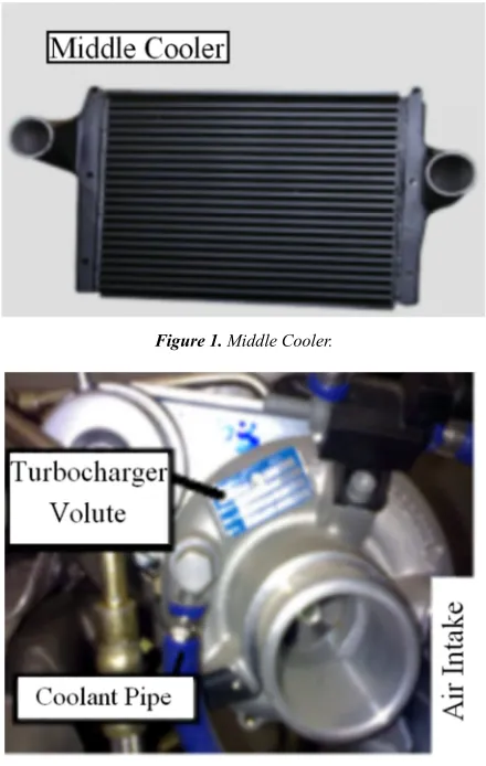
Turbocharger coolant system consists of the following aspects: mainly including cooling water pipes: connecting water jackets and turbochargers; air-cooled middle coolers, turbochargers, etc. In Figure 1 is an middle cooler and Figure 2 shows a turbocharger [4, 5, 6].
Figure 1. Middle Cooler.
Figure 2. Turbocharger.
Equipped with a middle cooler, the high-temperature gas is cooled before being injected into the cylinder, and the high-temperature and high-pressure air is dispersed into many small pipes, and the high-temperature air flows through the normal temperature outside the pipe to achieve the purpose of cooling and improve the charging efficiency [7].
3. Method of the Researches on the
Influences of the Intake Air
Temperature on the Otto Cycle
The Otto cycle refers to the ideal reversible cycle of constant volume heating of a gasoline engine: an irreversible constant volume heat release, a reversible constant volume heat absorption and an ideal inner reversible cycle composed of two degenerative processes. The intake air temperature has a fairly direct impact on the Otto cycle of the gasoline engine. The maximum torque of the gasoline engine is the maximum torque speed, the natural inhalation temperature is 290K, 17°C, without the middle cooler, the temperature of the pressurized air can reach 77°C, that is 350K, and in the case of equipment middle cooler, The intake air temperature can be reduced by 30°C, that is 47°C, 320K.Details are shown in table 2[8].
Basic Formulas
(1)Cycle Heat Efficiency
1
1 1
t c κ η
ε −
= − ----Only for Otto Cycle (1)
(2)Average Valid Pressure of the Cycle
a a
1
1 1
t t B c
V c
p Q
p c T
η ε
κ ε
=
− −
(2)
(3)Exergy and Exergy Efficiency
Heat Exergy in Heat Absorption Capacity QB :
0
, , 0 1
1
(1 )
x Q B n Q B B
m T
e Q a Q Q T s
T
= − = − = − ∆ (3)
Average Temperature of Heat Absorption:
1 1 B m
Q T
s
=
∆ (4)
Exergy Efficiency:
,
x net e
x Q w e
η = (5)
Among: ex Q, - Heat Exergy, kJ/kg; an Q, - Heat Anergy,
kJ/kg; T1m - Average Temperature of Heat Absorption, K;
B
Q - Cycle Heat Absorption Capacity, kJ/kg; T0 -
Exergy(Cycle Work), kJ/kg; Exergy Loss:
2
0 0 2 0 0 1 2 , 2 0 1
0
( ) ( )
g n Q
Q
i T s T s s T s Q a Q T s
T
= = ∆ + ∆ = −∆ + = − = − ∆ (6)
Among them: i-Exergy Loss, kJ/kg; sg -Entropy
Generation, kJ/(kg.K); ∆s0- Environment Entropy Increase
during Exothermic Process, kJ/(kg.K); Q2 -Cycle Heat
Release, kJ/kg; ∆s2 -Entropy Increase during Exothermic Process, kJ/(kg.K)
4. Results of the Researches on the
Influences of the Intake Air
Temperature on the Otto Cycle
Boundary Conditions and Research Results
Table 2 is the air intake temperature condition.
Table 2. Air Intake Condition.
Intake Temperature Temp. before Turbocharged
Temp. after Turbocharged without Middle Cooler 290K 350K
with Middle Cooler 290K 320K
The article mainly researches and analysis the cycle heat efficiency, cycle average valid pressure and exergy efficiency in the Otto cycle with and without middle cooler.
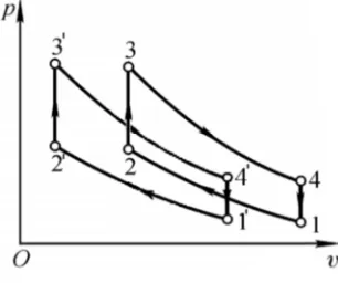
Figure 3 and figure 4 show p-v and T-s charts of the Otto cycle, among them, the number with a ‘’’ refers to be with a middle coolant, without a ‘’’ refers to be without one. Thus, it will lead the air charging efficiency increase, at the same time, acquire larger output power.
There are several relevant parameters below: Compression ratio:
c
ε =8.5 (7)
Constant Entropy index:
κ=1.4 (8)
0.718 / ( )
V
c = kJ kg Ki (9)
1.005 / ( )
p
c = kJ kg Ki (10)
Without middle cooler, point 1 state:
a 1.75
p = bar (11)
a 350
T = K (12)
With middle cooler, point 1’ state:
a' 1.75
p = bar (13)
a' 320
T = K (14)
Highest pressure:
3 3' 80
p = p = bar (15)
Comment: 1→1’ Entropy Increase:
1 1
11'
1 1
' ' 320
ln ln 1.005 ln 0.09 / ( ) 0
350
p g
T p
s c R kJ kg K
T p
∆ = − = = − <
i (16)
Therefore, 1→1’ Entropy Increase is minus value, point 1’ is at the left down side in T-s chart (Figure 3).
Figure 3. p-v chart of Otto cycle.
Figure 4. T-s chart of Otto cycle.
From formula (2) could be concluded that the cycle heat efficiency ηt is only related to the compression ratio εc,so
the cycle heat efficiency is equal whether the middle cooler is installed. Substituting data,
t
Calculation of the Cycle Heat absorption QB
1→2 constant entropy process,
1 1
2 2 a a
T vκ− =T vκ− (19)
Then,
1
2 a
−
= c
T Tεκ (20)
Substitute relevant data,
2 824
T = K
T2'=753K (21)
Through
2 2 a a
p vκ = p vκ (22)
Substitute relevant data,
2 2' a c 35
p = p = p
ε
κ = bar (23)2→3 reversible constant volume
3 2
3 2
p p
T = T (24)
Substitute relevant data ,
3 1883
T = K (25)
3' 1721
T = K (26)
3 2
( ) 0.718 (1883 724) 760.4 /
B V
Q =c T −T = × − = kJ kg (27)
3 2
' ( ' ') 0.718 (1721 753) 695.0 /
B V
Q =c T −T = × − = kJ kg (28)
Cycle average valid pressure
Substitute relevant data to formula (2),
8.63
t
p = bar (29)
' 8.73
t t
p = bar> p (30)
It is worth mentioning that: in the theoretical calculation, the average valid pressure pt of the cycle is equal whether or
not equipped with an middle cooler; but in actual experiments, the intake air temperature will rise due to the absence of the middle cooler, and the time will cause the intake pipe seal softened, the intake seal will be not tight, and a small amount
t
p of gas is leaked, resulting in the average valid pressure of
the cycle being lower than the average valid pressure pt' of the cycle equipped with the middle cooler. The specific experimental conditions can be referred to the reference [8, 9].
3→4 constant entropy process,
1 1
4 4 3 3
T vκ− =T vκ− (31)
1 4 3 1 c T T κ
ε
− = (32)
Substitute relevant data,
4 800
T = K (33)
4' 731
T = K (34)
Heat Release,
2 V( 4 1) 0.718 (850 350) 323.1 /
Q =c T −T = × − = kJ kg (35)
2' V( 4' 1') 0.718 (731 320) 295.1 /
Q =c T −T = × − = kJ kg (36)
Efficient Exergy,
2 760.4 323.1 437.3 /
net B
w =Q −Q = − = kJ kg (37)
2
' ' ' 695.0 295.1 399.9 /
net B
w =Q −Q = − = kJ kg (38)
Entropy Increase during Heat Absorption Process:
3 3 3
23 2'3'
2 2 2
1883
ln ln 0.718 ln 0.718 ln 0.593 / ( )
824
V g
T v T
s c R kJ kg K s
T v T
∆ = + = = = = ∆
i (39)
Heat Anergy in Heat Absorption Capacity:
, = ∆0 23=290 0.593 172.0× = / = , '
n Q n Q
a T s kJ kg a (40)
Heat Exergy in Heat Absorption Capacity:
, , 760.4 172.0 588 /
x Q B n Q
e =Q −a = − = kJ kg (41)
, ' ' , ' 695.0 172.0 523 / x Q B n Q
e =Q −a = − = kJ kg (42)
Average Temperature of Heat Absorption:
1 23 760.4 1282 0.593 B m Q T K s = = =
∆ (43)
1 2'3' ' 695.0 ' 1172 0.593 B m Q T K s = = =
∆ (44)
Exergy Efficiency: ' 399.9 ' 76.46% ' 523 x net e x,Q w η = = =
e (45)
437.3 74.37% 588 x net e x,Q w η = = =
e (46)
ambient temperature , T0 and there will be an exergy loss,
the same below.
Exergy Loss:
0 g 2 n Q, 323.1 172.0 151.1 /
i=T s =Q −a = − = kJ kg (47)
0 2 ,
' g' ' n Q' 295.1 172.0 123.1 /
i =T s =Q −a = − = kJ kg (48)
Table 3 is the contrast of the Otto cycle research results, under Otto cycle, in addition to the lifting compression ratio
c
ε , all the measures to improve the theoretical cycle thermal
efficiency ηt of the gasoline engine, and increase the inlet pressure pa of the cycle starting point, reduce the intake air
temperature Ta, and improve the charging efficiency are all
beneficial to the increase of the cycle average effective pressure pt, the efficiency of the exergy ηex and the output
power.
In addition, the turbocharged gasoline engine equipped with an middle cooler has an intake air temperature and a circulating average valid pressure and exergy efficiency also have certain advantages.
Table 3. Contrasts of research results of Otto cycle.
Middle coolant Thermal Efficiency Heat absorption Average valid p. Exergy Efficiency
N 57,5% 760.4kJ/kg 8.63bar 74.37%
Y 57.5% 695.0kJ/kg 8.73bar 76.46%
Experiment Comparison
Table 4 shows the contrasts of the calculation results and the experiment result, through the thermal balance experiment, the basic data is corresponding with each other, it can be concluded that the calculation method and results are convincing and corresponding basically.
Table 4. Comparison of the calculation results and thermal balance results.
Parameter(rated speed) Calculation Experiment Error Rate
Intake Pressure 1.75bar 1.85bar 20%
Outlet Pressure 1074mbar 849mbar 15%
Water Inlet Temp. 105°C 92.7°C 11%
Water Outlet Temp. 109.2°C 99.1°C 12%
Difference Temp. between Water inlet and outlet 4.2°C 6.4°C 25%
Through the table above, there are still some error rates between the calculation and experiment results, they’re mainly caused from the situation of the experiment, however, the rates are basically within the limits of the acceptance and reasonable, could be ignored[9].
Additional Introductions
The above are the effects and advantages of the middle cooler on the turbocharged gasoline engine; in addition to the advantages of improving the power and economy of the gasoline engine, the turbocharging technology itself also reflects:
(1)The quality and design size of the turbocharger are relatively small compared with that of the gasoline engine. When the turbocharged pressure can make the total mass and volume of the gasoline engine basically unchanged, the output power is greatly improved, the power is increased, the specific power is The specific volume power is greatly improved, which can reduce the cost per unit of power and enhance the utilization rate of materials;
(2)Compared with naturally aspirated gasoline engines, the exhaust gas can be further expanded in the turbine to reduce exhaust noise[10, 11, 12];
(3)After the gasoline engine is turbocharged, it is beneficial to the power recovery under the condition of thin air in the plateau, so that it can reach or approach the lower altitude performance, more stable, enhanced and efficient.
5. Conclusions
The concepts of the gasoline engine turbocharged system and the structure and working principle of the 486 turbocharged gasoline engine turbocharged system are introduced. The difference in structure and working principle of the gasoline engine turbocharged system equipped with the middle cooler and without middle cooler is after calculation and experimental research, the intake air temperature, exergy efficiency and average valid pressure of the gasoline engine Otto cycle are obtained. The calculation and experimental results show correction of the calculation process, and the middle cooler has the intake air temperature and the exergy efficiency.
And the average effective pressure has certain advantages; introduce the advantages of the gasoline engine turbocharged system on all aspects of the gasoline engine.
References
[1] Liu Feng 2018(Jan.) Research on the Exergy of Automobile Engine inner Cylinder Thermal Cycle J. Automobile Parts. 41-45.
[2] Liu Feng 2017(Nov.) Research on the Exergy of Automotive Engine inner Cylinder Thermal Cycle J. Auto Time. 89-92. [3] Liu Feng 2017(Mar.) Research on the Sabah Cycle of Diesel
[4] Liu Feng 2017(Apr.) Calculation on the Sabah Cycle with a Common Rail Injection System Compared with Diesel Cycle J. Automobile Parts. 62-64.
[5] Liu Feng 2017(May) The Influences of Common Rail Pressure on Sabah Cycle J. Automobile Parts. 63-65.
[6] F Liu. Research and Analysis on the exergy of Automotive Engine Inner Cylinder Thermal Cycle[J]. International Journal of Engineering Sciences & Research Technology: Vol. 7 Iss. 2, Feb. 25th, 18: 539-545.
[7] F Liu. Analysis on the exergy of Automobile Engine Inner Cylinder Thermodynamic Cycle[J]. Global Journal of Advanced Engineering Technologies & Sciences: 5(2), Feb. 28th,18: 30-36.
[8] Liu Feng 2016(Dec.) Research on the Intake Temperature Influences of Turbocharged Gasoline’s Otto Cycle J.Auto Time. 80-81.
[9] Liu Feng 2013(Dec.) Simulation Analysis Research on the Coolant System of Turbo Gasoline Engine with Flowmaster J. Small Internal Combustion Engine and Motorcycle. 53-58. [10] Liu Feng 2017(Mar.) Researches on the Contrasts between
Sabah Cycle with a Common Rail Injection System and Diesel Cycle J. Auto Industry Research.57-62.
[11] Liu Feng 2017(Aug.) The Influences of Diesel’s Common Rail Pressure on Sabah Cycle J.Auto Industry Research. 57-62. [12] Feng Liu. Researches on the Influences of Common Rail