electronic Journal of Computer Science and Information Technology (eJCSIT), Vol. 3, No. 1, 2011
H. A. Sulaiman and A. Bade, Continuous Collision Detection for Virtual Environments: A Walkthrough of Techniques 1
Continuous Collision Detection for Virtual Environments:
A Walkthrough of Techniques
Hamzah Asyrani Sulaiman
Universiti Teknikal Malaysia Melaka 76109 Durian Tunggal, Melaka
Abdullah Bade
Universiti Malaysia Sabah 88999 Kota Kinabalu, Sabah
Abstract –Continuous Collision Detection (CCD) has been widely accepted as the common tool to detect collision between dynamic collisions of rigid and deformable models, especially for use as an accurate collision method. Performing a computationally intensive technique for detecting between two configurations that focuses on accuracy always slows detection as compared to discrete collision detection (DCD). CCD algorithms focus on the motions toward objects regarding any interpolation as long as it can be detected before it can penetrate the object. While DCD requires backtracking after collision has been detected, CCD does not suffer the same problems as DCD. CCD also avoids the tunnelling problem that exists in DCD algorithms where penetration always occurs to the object (missed the collision). This paper will provide current and future research of CCD algorithms, which eventually will become the framework of our CCD algorithm technique for our research.
Keywords – Continuous Collision Detection; Collision Detection; Bounding-Volume Hierarchies
I. INTRODUCTION
Collision detection (CD) has been widely use in various types of applications such as robotics, computer graphics and physically based modelling. For those types of applications, reliable and fast collision detection algorithms are required for such simulation in order to bring realistic force of non-penetration constraints. Collision detection has been widely studied over the past two decades based on various types of research that have been conducted in order to increase the performance of simulation especially in computer games and other virtual simulations such as avatar for motion movements and urban simulation for wide-scale interactive simulations. At the earlier age of CD approach, most prior works were on static scenes where their intersection needs to be determined. However, current research areas have focused on dynamic scenes where objects are moving. The object movement may be known in advance, as it requires determining the possible collision with certain other objects. In sampling-based robot motion planning, robot movement may need to determine its future directions in order to find the possible collision with certain objects around the robot’s area movement and eventually use the data that has been collected by sensors in order to compute a continuous collision-free path from its current position until the end of the robot’s movement position.
At an initial level of collision detection, there are two subparts of dynamic collision detection algorithms which are discrete collision detection (DCD) and continuous
collision detection (CCD). Discrete collision detection only detects collisions at discrete moments in time; see examples in [3-18]. The consequence is, it may miss the collision between two successive configurations. This is also known by researchers as the tunnelling problem. Continuous collision detection performs a higher-order check to find out if there are any intersections between two objects through the distance defined by configuration points. It happens a lot when the object has thin surfaces or fast affecting objects that eventually missed the collision. It is important for high-fidelity simulations even though it is not required for fast response simulations such as in computer games or animations. Meanwhile continuous collision detection (CCD) algorithms resolve the tunnelling problem by first using the interpolated motions to check for continuous movement in collisions, motion interpolation between successive configurations, and use the interpolated motions to check for continuous movement collisions. Thus, CCD hardly misses any potential collision between those configurations.
Most CCD algorithms are used in sampling-based motion planning [9], and robotics collision to find the first intersection to apply responsive forces [19-21]. However, the drawback of CCD algorithms is that they are slow compared to DCD algorithms because they constantly check for collisions between configurations. That is the reason why most researchers seem to put more attention on DCD algorithms compared to CCD algorithms. Most researchers that use CCD algorithms limit their attention to polyhedral or articulated models. Others just use DCD to perform collision detection as there is no connectivity information except like that of polyhedral and articulated models.
II. COLLISION DETECTION OVERVIEW
A. Overview
Detecting object interference in 3D applications is always a challenging problem for researchers. Compared to the real world, performing fast and accurate collision detection is never an easy task, as each object that contains triangles must be checked for interactions. For example, when a collision occurs between two geometric models that have 1000 triangles for each of them, the corresponding system must check every triangle on one object between triangles in another object. Thus, it is very expensive just to detect collision between only two objects that have only 1000 triangles. Any application that has a collision detection system must be aware of this limitation and find a solution to overcome it. Apart from that, memory management in any 3D application must be considered. Furthermore, there are some other criteria and important issues that need to be measured when designing a 3D application. For instance, in 3D games, animation and simulation, there is a need to maintain the application’s speed running with suitable frame rates of 30-60 fps [25-27]. Apart from that, there is a need to balance between the realism and the complexity of the applications as well [3, 28].
Theoretically, in order to simulate or design our 3D application, certain criteria and important issues need to be considered. For instance, in 3D games, animation and simulation, there is a need to maintain the application’s running speed of suitable frame rates as high as 30-60 fps [4, 11, 29]. To achieve that goal, the applications developed should undergo appropriate construction techniques to minimize memory consumption using some optimization method. Furthermore, it is necessary to balance between the realism and the complexity of the applications [4, 29].
B. Discrete Collision Detection and Distance Calculation
The virtual world differs from the real world in many terms such as how the geometric object in the virtual world behaves (physics effects, etc.), how the gravity in the real world differs from the virtual world and so on. Moreover, the big differences between the real world and the virtual environment are the objects themselves where the real world contains unlimited objects whereas the virtual environment can only generate a certain number of objects. However, the limitations of the virtual environment bring researchers to continue to produce high quality virtual worlds where the experiences in the virtual world are almost the same as the real world. Various virtual world applications such as computer games (first person shooter, racing car, etc.), online games (Second Life, World of Warcraft, etc.) and walkthrough city simulation, for example, have been developed to satisfy people using new ways of entertainment.
One of the important aspects that greatly affects the realism of the virtual world which we can experience is
the limitation of two or more objects that cannot share the same space at the same time. The constraint of this aspect will definitely result in some restrictions to our movement and this limitation has a great impact on the virtual world. However, objects that have impenetrability will enable us to perform tasks such as stacking a pile of cards and grabbing things in the virtual world.
In the virtual world, geometric objects do not have impenetrability on their own after being modelled using 3D tools. However, we are able to create a mechanism to handle impenetrability by introducing a technique called collision detection. Collision detection has a broad meaning and covers many applications; for instance in 3D simulation and animation, engineering (e.g., robotics), virtual reality environments, and even networking. According to Moller et al. [30], collision detection can be divided into three main parts: collision detection, collision determination, and collision response. Collision detection occurs when two or more solid objects (simple or complex) come into contact (e.g., cars collide with each other). Collision determination will try to find the exact contact between colliding objects. Next, collision response will react after the collision has been detected either by appointing new positions or by changes of shape for both objects.
C. Continuous Collision Detection
CCD is almost the same with DCD except in terms of how the detection process is implemented. There are various types of CCD algorithms that have been proposed in the literature. Figure 1 shows the difference between DCD and CCD algorithms.
H. A. Sulaiman and
One of the advantages of CCD from the tunnelling
missed if the simulation has low frame Furthermore, CCD is
detection data collection, such as point of contact, time of contact, and normal of contact.
and DCD methods.
accepted because of the requirement to deal with the dynamic nature of 3D applications. It has received attention from various research communities because it offers robust handling of non
rigid bodies. CCD based on
Figure 1.Differences between DCD method (a) and CCD method (b). DCD check
Figure 2.
electronic Journal of Computer Science and Information Technology (eJCSIT), Vol. 3, No. 1, 2011
and A. Bade, Continuous he advantages of CCD tunnelling effect,
missed if the simulation has low frame Furthermore, CCD is perfect
detection data collection, such as point of contact, time of contact, and normal of contact.
methods. Recently, CCD has become widely accepted because of the requirement to deal with the dynamic nature of 3D applications. It has received ttention from various research communities because it offers robust handling of non
rigid bodies. Readers are encourage n figure 2.
Differences between DCD method (a) and CCD method (b). DCD check calculation technique that continuously checks for intersection
Figure 2. CCD techniques
ronic Journal of Computer Science and Information Technology (eJCSIT), Vol. 3, No. 1, 2011
Continuous Collision Detection for Virtual Environment he advantages of CCD is it does not suffer
and no collision is going to be missed if the simulation has low frame
perfect for accurate collision detection data collection, such as point of contact, time of contact, and normal of contact. Figure 1 depicts the CCD Recently, CCD has become widely accepted because of the requirement to deal with the dynamic nature of 3D applications. It has received ttention from various research communities because it offers robust handling of non-penetration constraints fo
are encouraged to read paper
Differences between DCD method (a) and CCD method (b). DCD check calculation technique that continuously checks for intersection
echniques and implementation
ronic Journal of Computer Science and Information Technology (eJCSIT), Vol. 3, No. 1, 2011
Collision Detection for Virtual Environment it does not suffer
and no collision is going to be missed if the simulation has low frame-rates. for accurate collision detection data collection, such as point of contact, time of Figure 1 depicts the CCD Recently, CCD has become widely accepted because of the requirement to deal with the dynamic nature of 3D applications. It has received ttention from various research communities because it penetration constraints fo
to read paper
Differences between DCD method (a) and CCD method (b). DCD check calculation technique that continuously checks for intersection
mplementations
ronic Journal of Computer Science and Information Technology (eJCSIT), Vol. 3, No. 1, 2011
Collision Detection for Virtual Environment it does not suffer
and no collision is going to be rates. for accurate collision detection data collection, such as point of contact, time of Figure 1 depicts the CCD Recently, CCD has become widely accepted because of the requirement to deal with the dynamic nature of 3D applications. It has received ttention from various research communities because it penetration constraints for to read papers on
BVH
geometric models with specific bounding volumes. It works like a tree that has a root (
of leave node has it
The main idea of the BVH is to build a tree that has a primary and secondary root which each of the secondary nodes store
hierarchy is shown in Figure
Figure 3.
the right hand side image shows binary type hierarchy
BVH allow for
example, given two objects root
will not be done for both objects. However, when the root
intersection between one root of the hierarchies’ tree and the othe
it recursively checks again whether there is intersection between both objects at
correct intersection. Figure partitioned into several par
basic algorithms for detecting collision between two hierarchies
Differences between DCD method (a) and CCD method (b). DCD check calculation technique that continuously checks for intersection
ronic Journal of Computer Science and Information Technology (eJCSIT), Vol. 3, No. 1, 2011
Collision Detection for Virtual Environments: A Walkthrough of Techniques III. BOUNDING
BVH is simply a tree structure that represents geometric models with specific bounding volumes. It works like a tree that has a root (
of leaves (middle division) and a leaf (last division). Each node has its bounding
The main idea of the BVH is to build a tree that has a primary and secondary root which each of the secondary nodes stored as a leaf.
hierarchy is shown in Figure
Figure 3. The left hand side image show the right hand side image shows binary type hierarchy
BVH allows the intersection for non-colliding
example, given two objects roots of the hierarchies
will not be done for both objects. However, when the roots of both hierarchies intersect, it checks for intersection between one root of the hierarchies’ tree and the other children of objects hierarchies’ tree. In this case, it recursively checks again whether there is intersection between both objects at
correct intersection. Figure partitioned into several par
basic algorithms for detecting collision between two hierarchies [37-38]
Differences between DCD method (a) and CCD method (b). DCD checks for certain time steps, while CCD uses calculation technique that continuously checks for intersections which are more
ronic Journal of Computer Science and Information Technology (eJCSIT), Vol. 3, No. 1, 2011
Walkthrough of Techniques
OUNDING-VOLUME
simply a tree structure that represents geometric models with specific bounding volumes. It works like a tree that has a root (
s (middle division) and a leaf (last division). Each bounding-volumes that cover t
The main idea of the BVH is to build a tree that has a primary and secondary root which each of the secondary
as a leaf. An example of bounding hierarchy is shown in Figure 3.
The left hand side image show
the right hand side image shows an unbalanced hierarchical f
the intersection
colliding pairs from the hierarchy tree. For example, given two objects with their BVH, when
of the hierarchies do not intersect, the calculation will not be done for both objects. However, when the of both hierarchies intersect, it checks for intersection between one root of the hierarchies’ tree and r children of objects hierarchies’ tree. In this case, it recursively checks again whether there is intersection between both objects at the middle level until i
correct intersection. Figure 3 partitioned into several parts w
basic algorithms for detecting collision between two 38].
tain time steps, while CCD uses more computationally intensive ronic Journal of Computer Science and Information Technology (eJCSIT), Vol. 3, No. 1, 2011
Walkthrough of Techniques
OLUME HIERARCHIES
simply a tree structure that represents geometric models with specific bounding volumes. It works like a tree that has a root (upper division), a group s (middle division) and a leaf (last division). Each
volumes that cover the child node The main idea of the BVH is to build a tree that has a primary and secondary root which each of the secondary
xample of bounding .
The left hand side image shows a BVH with Sphere BV while unbalanced hierarchical f
the intersection to occur without searching pairs from the hierarchy tree. For
with their BVH, when not intersect, the calculation will not be done for both objects. However, when the of both hierarchies intersect, it checks for intersection between one root of the hierarchies’ tree and r children of objects hierarchies’ tree. In this case, it recursively checks again whether there is intersection
middle level until i 3 shows how ts while Figure
basic algorithms for detecting collision between two
tain time steps, while CCD uses an advance computationally intensive [1]
3 IERARCHIES
simply a tree structure that represents geometric models with specific bounding volumes. It upper division), a group s (middle division) and a leaf (last division). Each he child nodes The main idea of the BVH is to build a tree that has a primary and secondary root which each of the secondary xample of bounding-volume
s a BVH with Sphere BV while unbalanced hierarchical form using
without searching pairs from the hierarchy tree. For with their BVH, when the not intersect, the calculation will not be done for both objects. However, when the of both hierarchies intersect, it checks for intersection between one root of the hierarchies’ tree and r children of objects hierarchies’ tree. In this case, it recursively checks again whether there is intersection middle level until it finds the shows how the object is igure 4 depicts the basic algorithms for detecting collision between two
advanced motion
3
simply a tree structure that represents geometric models with specific bounding volumes. It upper division), a group s (middle division) and a leaf (last division). Each s. The main idea of the BVH is to build a tree that has a primary and secondary root which each of the secondary volume
s a BVH with Sphere BV while orm using
A.
Figure 4. BVH traversal algorithm proposed by
A. BVH Construction
There are multiple types of BVH construction
be used to represent hierarchical representation. Among the popular ones
definitions:-
a) Nodes
condition that represents a separate data structure or a tree of its own. In BVH, it contains bounding
may become computer science tree
the root is at the top of the tree). The node that gives
or a
height of the tree is determined by the length starting from root node down to the leaf no The depth of the tree is the length of the path to its root.
b) Root Nodes
tree is called
not have any parents. It is the starting node where all the operations of
norm
child nodes downward of a branch or
tree connect
c) Leaf Nodes
binary tree
have any child nodes and mostly contain the last value or conditions. In BVH,
contain
d) Internal Nodes
both parent
node as it still has child nodes and parent node.
e)
Sub-can be viewed as a complete tree in itself. It repres
manipulated by
Beginning at the root nodes of two given trees
1. Check for intersection between two parent nodes 2. If there is no intersection between two parents 3.
4. Else check all children of one node against all children of the other node
5. If there is intersection between any children 6.
7. 8.
9. Else
Figure 4. BVH traversal algorithm proposed by detection between two BVH
BVH Construction
There are multiple types of BVH construction
be used to represent hierarchical representation. Among ones is binary tree. Binary tree has some node
Nodes – A node may contain specific value or a
condition that represents a separate data structure or a tree of its own. In BVH, it contains bounding-volume with their tree ID. Each node may become a parent, child or leaf node (in computer science tree
the root is at the top of the tree). The node that s birth to a child node
a superior node
height of the tree is determined by the length starting from root node down to the leaf no The depth of the tree is the length of the path to its root.
Root Nodes – The topmost node in tree is called the
not have any parents. It is the starting node where all the operations of
normally. The root node is child nodes downward of
branch or sub-tree connecter is connects each node
Leaf Nodes – The bottommost node
binary tree are call
have any child nodes and mostly contain the last value or conditions. In BVH,
contain a few triangles or
Internal Nodes –
both parent nodes and child nodes. It is not node as it still has child nodes and parent node.
-tree – A portion of a tree data structure that can be viewed as a complete tree in itself. It represents some other part
nipulated by the
Beginning at the root nodes of two given trees
Check for intersection between two parent nodes If there is no intersection between two parents
Then stop and
lse check all children of one node against all hildren of the other node
If there is intersection between any children Then if at
Else go to Step 4 Else stop and report
Figure 4. BVH traversal algorithm proposed by detection between two BVH
There are multiple types of BVH construction
be used to represent hierarchical representation. Among is binary tree. Binary tree has some node
A node may contain specific value or a condition that represents a separate data structure or a tree of its own. In BVH, it contains
volume with their tree ID. Each node parent, child or leaf node (in computer science trees grow downward where the root is at the top of the tree). The node that
child node is called superior node (or an ancestor node height of the tree is determined by the length starting from root node down to the leaf no The depth of the tree is the length of the path to
The topmost node in the root node. The root node not have any parents. It is the starting node where all the operations of the
The root node is connected to each child nodes downward of the root node by using
tree connector.
connecter is an important element that s each node with their parent nodes.
The bottommost node called leaf nodes.
have any child nodes and mostly contain the last value or conditions. In BVH,
few triangles or perhaps – The functional node nodes and child nodes. It is not node as it still has child nodes and
A portion of a tree data structure that can be viewed as a complete tree in itself. It ents some other part of the tree that can be
the user in programming.
Beginning at the root nodes of two given trees
Check for intersection between two parent nodes If there is no intersection between two parents
Then stop and report “no collision” lse check all children of one node against all hildren of the other node
If there is intersection between any children f at a leaf node
Report “possible collision” Else go to Step 4
and report “no collision”
Figure 4. BVH traversal algorithm proposed by [38] for collision detection between two BVH
There are multiple types of BVH constructions that can be used to represent hierarchical representation. Among is binary tree. Binary tree has some node
A node may contain specific value or a condition that represents a separate data structure or a tree of its own. In BVH, it contains
volume with their tree ID. Each node parent, child or leaf node (in
downward where the root is at the top of the tree). The node that
called a parent node ancestor node). The height of the tree is determined by the length starting from root node down to the leaf no The depth of the tree is the length of the path to
The topmost node in the binary The root node not have any parents. It is the starting node
the tree will begin connected to each root node by using connector. A branch or
important element that with their parent nodes. The bottommost nodes in
leaf nodes. They do not have any child nodes and mostly contain the last value or conditions. In BVH, leaf nodes
perhaps one triangle. The functional node that nodes and child nodes. It is not a node as it still has child nodes and is linked by
A portion of a tree data structure that can be viewed as a complete tree in itself. It of the tree that can be user in programming.
Check for intersection between two parent nodes If there is no intersection between two parents
report “no collision” lse check all children of one node against all
If there is intersection between any children
eport “possible collision”
for collision
that can be used to represent hierarchical representation. Among is binary tree. Binary tree has some node
A node may contain specific value or a condition that represents a separate data structure or a tree of its own. In BVH, it contains a volume with their tree ID. Each node parent, child or leaf node (in downward whereas the root is at the top of the tree). The node that parent node . The height of the tree is determined by the length starting from root node down to the leaf node. The depth of the tree is the length of the path to
binary The root node does not have any parents. It is the starting node tree will begin connected to each root node by using sub-important element that
in the do not have any child nodes and mostly contain the last may one triangle.
that has a leaf linked by a
A portion of a tree data structure that can be viewed as a complete tree in itself. It of the tree that can be
There are few common operations involved in construction and implementation of binary tree for BVH construction. Among them are enumerating all the items, searching for an item which is bounding
removing a
area when performing collision dete traversing
to the root, and report
two intersected BVH that possibility
B. BVH Splitting Rules
The first step of BVH construction is choosing the splitting rules that will divide the root node into two equal parts using
axis
at the longest axis at the splitting point based on the splitting rules. According to
common solution construction:
The details will be explained more the condition:
Figure 5. (a) Object median splitting, (b) Object mean splitting,
Meanwhile,
top-primitives by
recursively partitioned the bounded objects using a There are few common operations involved in construction and implementation of binary tree for BVH construction. Among them are enumerating all the items, searching for an item which is bounding
removing a whole section of a tree for area when performing collision dete
traversing down from the root to leaf nodes or leaf nodes to the root, and report
two intersected BVH that possibility
BVH Splitting Rules
The first step of BVH construction is choosing the splitting rules that will divide the root node into two equal parts using the binary type tree. Then, by using
axis-separating plane technique, the object will be divided at the longest axis at the splitting point based on the splitting rules. According to
common solution construction:
a. Median of the object coordi
– split at the object median (evenly distributed parts) resulting
b. Mean of object coordinates (object mean) at the object mean
c. Median of the bounding extent (spatial median) into two equal parts
The details will be explained more the condition:-
Figure 5. (a) Object median splitting, (b) Object mean splitting,
Meanwhile, [32, 40]
-down approach. The first procedure enclosed all primitives by using
recursively partitioned the bounded objects using a
Figure 6. Splitting along the farthest axis of object bounded with
There are few common operations involved in construction and implementation of binary tree for BVH construction. Among them are enumerating all the items, searching for an item which is bounding
whole section of a tree for area when performing collision dete
down from the root to leaf nodes or leaf nodes to the root, and reporting any intersected area between two intersected BVH that possibility
BVH Splitting Rules
The first step of BVH construction is choosing the splitting rules that will divide the root node into two equal
binary type tree. Then, by using
separating plane technique, the object will be divided at the longest axis at the splitting point based on the splitting rules. According to
common solutions of choosing the splitting rules for BVH
Median of the object coordi
split at the object median (evenly distributed parts) resulting in a well
Mean of object coordinates (object mean) at the object mean.
Median of the bounding extent (spatial median) into two equal parts.
The details will be explained more
Figure 5. (a) Object median splitting, (b) Object mean splitting, (c) Spatial median splitting
[32, 40] constructed OBB trees using down approach. The first procedure enclosed all
using an oriented bounding
recursively partitioned the bounded objects using a
Figure 6. Splitting along the farthest axis of object bounded with OBB using centre points
There are few common operations involved in construction and implementation of binary tree for BVH construction. Among them are enumerating all the items, searching for an item which is bounding
whole section of a tree for a non
area when performing collision detection (called pruning), down from the root to leaf nodes or leaf nodes any intersected area between two intersected BVH that possibility in collision.
The first step of BVH construction is choosing the splitting rules that will divide the root node into two equal
binary type tree. Then, by using
separating plane technique, the object will be divided at the longest axis at the splitting point based on the splitting rules. According to [8, 39], there
of choosing the splitting rules for BVH
Median of the object coordinates (object median) split at the object median (evenly distributed
a well-balanced tree. Mean of object coordinates (object mean)
Median of the bounding-volume projection extent (spatial median) – splitting the volume
The details will be explained more later. Figure 5 depicts
Figure 5. (a) Object median splitting, (b) Object mean splitting, (c) Spatial median splitting
constructed OBB trees using down approach. The first procedure enclosed all
an oriented bounding-box, and then it recursively partitioned the bounded objects using a
Figure 6. Splitting along the farthest axis of object bounded with OBB using centre points [32]
There are few common operations involved in the construction and implementation of binary tree for BVH construction. Among them are enumerating all the items, searching for an item which is bounding-volume, a non-intersected ction (called pruning), down from the root to leaf nodes or leaf nodes any intersected area between
in collision.
The first step of BVH construction is choosing the splitting rules that will divide the root node into two equal binary type tree. Then, by using the longest separating plane technique, the object will be divided at the longest axis at the splitting point based on the , there are three of choosing the splitting rules for BVH
nates (object median) split at the object median (evenly distributed
balanced tree.
Mean of object coordinates (object mean) – split
volume projection ng the volume
. Figure 5 depicts
Figure 5. (a) Object median splitting, (b) Object mean splitting,
constructed OBB trees using a down approach. The first procedure enclosed all
box, and then it recursively partitioned the bounded objects using a rule.
Figure 6. Splitting along the farthest axis of object bounded with
the construction and implementation of binary tree for BVH construction. Among them are enumerating all the items, volume, intersected ction (called pruning), down from the root to leaf nodes or leaf nodes any intersected area between
The first step of BVH construction is choosing the splitting rules that will divide the root node into two equal longest separating plane technique, the object will be divided at the longest axis at the splitting point based on the three of choosing the splitting rules for BVH
nates (object median) split at the object median (evenly distributed
split
volume projection ng the volume
. Figure 5 depicts
a down approach. The first procedure enclosed all box, and then it rule.
H. A. Sulaiman and
Their ‘subdivide
splitting point with a plane orthogonal to either one of its axes and split it into two subsets. Objects
according to which side of the splitting point primitives are never cut. Figure
splitting example
C. Object Median
From figure
point. By calculating the median of each triangle, the object median point is equally distributed by finding the middlemost point between the median of all triangles. Then, it checks for the separating plane according to the median point of the triangle. According to
median requires O (n log n)
However, it is also reported that by using more sophisticated method
but this increase
[41]. This is because the median point of object median needs to be determine
take longer for the tree to be constructed.
D. Object Mean and O
Based on [5]
the centred coordinates. The object mean technique can result in tighter volume trees with
perform without splitting technique splits according into evenly spaced
find the best point. By using a brute force approach method finds
random subset of the primitive centre coordinates. However, due to the complex implementation
seldom use it.
IV.
Performing collision detection between rigid bodies using ‘primitive
expensive computation cost. Some buildings might have thousands of polygons
collision when some other objects intersection test
force approach, each primitive will be tested fo until the program fi
one of the way to handle this is to use a Bounding Volume (BV).
Figure 7.
electronic Journal of Computer Science and Information Technology (eJCSIT), Vol. 3, No. 1, 2011
and A. Bade, Continuous
subdivide’ rule is to find the longest axis of a box splitting point with a plane orthogonal to either one of its axes and split it into two subsets. Objects
according to which side of the splitting point are never cut. Figure
splitting example [32, 40].
Object Median
From figure 6, Object Median split
point. By calculating the median of each triangle, the object median point is equally distributed by finding the point between the median of all triangles. it checks for the separating plane according to the median point of the triangle. According to
median requires O (n log n)
However, it is also reported that by using more sophisticated methods, median can be found in O (n) time increases the heuristic usage at the earlier phase . This is because the median point of object median
to be determined using some heuristic take longer for the tree to be constructed.
Object Mean and Other
[5], the object is divided by using
the centred coordinates. The object mean technique can tighter volume trees with
perform without unbalancing splitting techniques, such as the splits according to BV projection. It sp
into evenly spaced points instead of using heuristic est point. By using a brute force approach finds the best possible
random subset of the primitive centre coordinates. However, due to the complex implementation
.
IV. BOUNDING
Performing collision detection between rigid bodies primitive-primitive’
xpensive computation cost. Some buildings might have thousands of polygons that
collision when some other objects
intersection tests with the buildings. By using force approach, each primitive will be tested fo
until the program finds the correct intersection point. So, one of the way to handle this is to use a Bounding Volume (BV).
Figure 7. Examples of common BVs as described in
ronic Journal of Computer Science and Information Technology (eJCSIT), Vol. 3, No. 1, 2011
Continuous Collision Detection for Virtual Environment rule is to find the longest axis of a box
splitting point with a plane orthogonal to either one of its axes and split it into two subsets. Objects
according to which side of the splitting point are never cut. Figures 5 and 6
, Object Median split
point. By calculating the median of each triangle, the object median point is equally distributed by finding the point between the median of all triangles. it checks for the separating plane according to the median point of the triangle. According to
median requires O (n log n) of time to sort all the points. However, it is also reported that by using more , median can be found in O (n) time the heuristic usage at the earlier phase . This is because the median point of object median
using some heuristic take longer for the tree to be constructed.
ther Splitting Rules
object is divided by using
the centred coordinates. The object mean technique can tighter volume trees with fewer
ing the tree by
such as the BV projection method BV projection. It sp
points instead of using heuristic est point. By using a brute force approach
possible splitting point between random subset of the primitive centre coordinates. However, due to the complex implementation
OUNDING-VOLUME (BV)
Performing collision detection between rigid bodies ’ intersection checking require xpensive computation cost. Some buildings might have
that need to be checked for collision when some other objects
with the buildings. By using force approach, each primitive will be tested fo
the correct intersection point. So, one of the way to handle this is to use a Bounding
Examples of common BVs as described in
ronic Journal of Computer Science and Information Technology (eJCSIT), Vol. 3, No. 1, 2011
Collision Detection for Virtual Environment rule is to find the longest axis of a box
splitting point with a plane orthogonal to either one of its axes and split it into two subsets. Objects are partitioned according to which side of the splitting point it lies but the
5 and 6 depict
, Object Median splits at the median point. By calculating the median of each triangle, the object median point is equally distributed by finding the point between the median of all triangles. it checks for the separating plane according to the median point of the triangle. According to [39], o
time to sort all the points. However, it is also reported that by using more , median can be found in O (n) time the heuristic usage at the earlier phase . This is because the median point of object median using some heuristics that ma take longer for the tree to be constructed.
ules
object is divided by using the mean of the centred coordinates. The object mean technique can fewer operations to by too much. Other BV projection method BV projection. It splits the projection
points instead of using heuristic est point. By using a brute force approach, this
splitting point between random subset of the primitive centre coordinates. However, due to the complex implementation, researchers
(BV)
Performing collision detection between rigid bodies intersection checking require xpensive computation cost. Some buildings might have
need to be checked for collision when some other objects are undergoing with the buildings. By using a brute force approach, each primitive will be tested for collision the correct intersection point. So, one of the way to handle this is to use a Bounding
Examples of common BVs as described in [2]
ronic Journal of Computer Science and Information Technology (eJCSIT), Vol. 3, No. 1, 2011
Collision Detection for Virtual Environment rule is to find the longest axis of a box
splitting point with a plane orthogonal to either one of its partitioned lies but the depict the
at the median point. By calculating the median of each triangle, the object median point is equally distributed by finding the point between the median of all triangles. it checks for the separating plane according to the , object time to sort all the points. However, it is also reported that by using more , median can be found in O (n) time the heuristic usage at the earlier phase . This is because the median point of object median that may
mean of the centred coordinates. The object mean technique can operations to too much. Other BV projection method, lits the projection points instead of using heuristics to , this splitting point between a random subset of the primitive centre coordinates. researchers
Performing collision detection between rigid bodies intersection checking requires xpensive computation cost. Some buildings might have need to be checked for undergoing brute collision the correct intersection point. So, one of the way to handle this is to use a
Bounding-The purpose of using computational cost
the object performs primitive applying BV, it could consume check each triangle with However,
be reduced with
object in order to perform collision dete help perform
BVH provides a hierarchical represent split the single BV into certain level primitive
It can
at certain level respond, collide has others
At the present time, there are several as sphere
[43-Discrete Oriented Polytope (k Polyhedra
large
because of its response [47]
bounding volume
In this implementation, we performed an in development of
used for future development of continuous collision detection method
behaves
The collision detection module wa creating a virtual world space
University 3D repository objects. Then, we ha for three
method. We believe that this implementation of BVH could be introduced for
approach in order to reduce the pairs testing between object triangle
Figure
implemented the BVH construction using a Pentium Core 2 Duo 2.2
PC800MH
ronic Journal of Computer Science and Information Technology (eJCSIT), Vol. 3, No. 1, 2011
Collision Detection for Virtual Environments: A Walkthrough of Techniques The purpose of using computational cost
the object performs primitive applying BV, it could consume check each triangle with However, the time
be reduced through enveloping with a BV. Instead of using
object in order to perform collision dete
help perform collision detection better than a single BV. BVH provides a hierarchical represent
split the single BV into certain level
primitive-primitive testing for accurate collision detection. It can also be used for fast collision detection by stopping at certain levels using
respond, approximately collides. It depends heavily o has been developed as
others, accuracy.
At the present time, there are several as spheres [42], Axis Aligned Bounding Bo
-45], Oriented Bounding Box (OBB) Discrete Oriented Polytope (k
Polyhedra [2], and hybrid combination BV large scale 3D simulations use
because of its simplicity, response toward
[47]. Figure 7 bounding volume
V. I
In this implementation, we performed an in development of a
used for future development of continuous collision detection method
behaves in virtual environment
The collision detection module wa creating a virtual world space
University 3D repository objects. Then, we ha for three 3D models using
method. We believe that this implementation of BVH could be introduced for
approach in order to reduce the pairs testing between object triangles.
Figures 8 through
implemented the BVH construction using Pentium Core 2 Duo 2.2
PC800MHz, GeForce 85
ronic Journal of Computer Science and Information Technology (eJCSIT), Vol. 3, No. 1, 2011
Walkthrough of Techniques The purpose of using a computational cost of detecting the object performs primitive applying BV, it could consume check each triangle with the
time required to check for each collision can through enveloping
BV. Instead of using a single BV for one particular object in order to perform collision dete
collision detection better than a single BV. BVH provides a hierarchical represent
split the single BV into certain level
primitive testing for accurate collision detection. be used for fast collision detection by stopping
using a stopping function or criterion approximately, to the collision as the object . It depends heavily on what kind of application been developed as some application
accuracy.
At the present time, there are several , Axis Aligned Bounding Bo , Oriented Bounding Box (OBB) Discrete Oriented Polytope (k-DOP)
, and hybrid combination BV scale 3D simulations use
simplicity, lower collisions, and eas illustrates the bounding volume techniques.
IMPLEMENTATION OF
In this implementation, we performed an in a collision detection system in order to be used for future development of continuous collision detection methods. It was done
in virtual environment
The collision detection module wa creating a virtual world space.
University 3D repository objects. Then, we ha 3D models using
method. We believe that this implementation of BVH could be introduced for a continuous col
approach in order to reduce the pairs testing between
8 through 10 depict
implemented the BVH construction using Pentium Core 2 Duo 2.2
z, GeForce 8500 GT
ronic Journal of Computer Science and Information Technology (eJCSIT), Vol. 3, No. 1, 2011
Walkthrough of Techniques
a BV is to reduce the ing an object’s interference. If the object performs primitive-primitive testing without applying BV, it could consume more time as it needs to
the other object’s
to check for each collision can through enveloping a highly complex object single BV for one particular object in order to perform collision detection, BVH could collision detection better than a single BV. BVH provides a hierarchical representation that could split the single BV into certain levels before performing primitive testing for accurate collision detection. be used for fast collision detection by stopping
a stopping function or criterion o the collision as the object
n what kind of application some application value
At the present time, there are several popular , Axis Aligned Bounding Bo , Oriented Bounding Box (OBB)
DOP) [5], Oriented Convex , and hybrid combination BV
scale 3D simulations use a bounding box lower storage requirement
, and ease of implement the most commonly used
MPLEMENTATION OF BVH
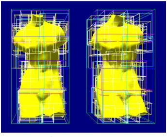
In this implementation, we performed an in collision detection system in order to be used for future development of continuous collision It was done to show how the BVH in virtual environments.
The collision detection module was developed by We inserted
University 3D repository objects. Then, we ha
3D models using a spatial median splitting method. We believe that this implementation of BVH continuous collision detection approach in order to reduce the pairs testing between
10 depict the BVH approach. We implemented the BVH construction using a machine with Pentium Core 2 Duo 2.2 GHz, 5 GB DDR2 RAM
00 GT with GPU support.
5
BV is to reduce the interference. If primitive testing without time as it needs to ’s triangle set. to check for each collision can highly complex object single BV for one particular ction, BVH could collision detection better than a single BV. ation that could before performing primitive testing for accurate collision detection. be used for fast collision detection by stopping a stopping function or criterion and
o the collision as the object n what kind of application value speed while
popular BVs such , Axis Aligned Bounding Box (AABB) , Oriented Bounding Box (OBB) [32, 45-46]
, Oriented Convex , and hybrid combination BVs [11]. Most bounding box technique requirement, fast implementation most commonly used
In this implementation, we performed an initial collision detection system in order to be used for future development of continuous collision to show how the BVH
s developed by inserted three Stanford University 3D repository objects. Then, we had a BVH
spatial median splitting method. We believe that this implementation of BVH lision detection approach in order to reduce the pairs testing between
the BVH approach. We a machine with , 5 GB DDR2 RAM
GPU support.
5
BV is to reduce the interference. If primitive testing without time as it needs to triangle set. to check for each collision can highly complex object single BV for one particular ction, BVH could collision detection better than a single BV. ation that could before performing primitive testing for accurate collision detection. be used for fast collision detection by stopping nd o the collision as the object n what kind of application speed while
BVs such x (AABB) 46], , Oriented Convex . Most technique , fast ation most commonly used
itial collision detection system in order to be used for future development of continuous collision to show how the BVH
s developed by Stanford a BVH spatial median splitting method. We believe that this implementation of BVH lision detection approach in order to reduce the pairs testing between
Figure 9.Teapots BVH level 8 and BVH level 9
VI. CONCLUSIONS AND FUTURE WORK
In this paper, we have described the current research of continuous collision detection (CCD) in virtual environments and bounding-volume hierarchies that will likely be used for the CCD approach. Simulating the environment with CCD is probably the hardest task for researchers, as it needs to continuously detect for collision, leaving behind the speed of intersection. However, it can provide a very accurate collision detection method compared to other techniques. Hence, this paper also provides a review of CCD research based on their current developments. In future, we hope to develop a framework based on the relevant literature in order to propose our own method in the continuous collision detection of the simulation of rigid bodies.
ACKNOWLEDGEMENTS
This research is supported by Universiti Teknikal Malaysia Melaka, and the Malaysian Ministry of Science, Technology and Innovation under their eScienceFund grant (VOT No. 79237).
REFERENCES
[1] P. Kipfer, "LCP Algorithms for Collision Detection Using CUDA," in GPU Gems 3. vol. 3, H. Nguyen, Ed., ed, 2007. [2] A. Bade, et al., "Oriented convex polyhedra for collision detection
in 3D computer animation," presented at the Proceedings of the 4th international conference on Computer graphics and interactive techniques in Australasia and Southeast Asia, Kuala Lumpur, Malaysia, 2006.
[3] J. D. Cohen, et al., "I-COLLIDE: an interactive and exact collision detection system for large-scale environments," presented at the Proceedings of the 1995 symposium on Interactive 3D graphics, Monterey, California, United States, 1995.
[4] P. M. Hubbard, "Collision detection for interactive graphics applications," Brown University, 1995.
[5] J. T. Klosowski, et al., "Efficient Collision Detection Using Bounding Volume Hierarchies of k-DOPs," IEEE Transactions on Visualization and Computer Graphics, vol. 4, pp. 21-36, 1998. [6] G. Zachmann, "Virtual Reality in Assembly Simulation -
Collision Detection, Simulation Algorithms, and Interaction Techniques," Department of Computer Science, Darmstadt University of Technology, Germany, 2000.
[7] S. Redon, et al., "Fast Continuous Collision Detection between Rigid Bodies," Computer Graphics Forum, vol. 21, pp. 279-287, 2002.
[8] G. V. D. Bergen, Collision Detection in Interactive 3D Environments. United States of America: Elsevier, Inc., 2004. [9] A. Benitez, et al., "Collision Detection Using Sphere-Tree
Construction," presented at the Proceedings of the 15th International Conference on Electronics, Communications and Computers, 2005.
[10] X. Zhang, et al., "Interactive continuous collision detection for non-convex polyhedra," Vis. Comput., vol. 22, pp. 749-760, 2006. [11] S. H. Kockara, T.; Iqbal, K.; Bayrak, C.; Rowe, Richard;,
"Collision Detection - A Survey," presented at the IEEE International Conference on Systems, Man and Cybernetics, 2007. ISIC., 2007.
[12] M. A. Otaduy, et al., "Balanced Hierarchies for Collision Detection between Fracturing Objects," in Virtual Reality Conference, 2007. VR '07. IEEE, 2007, pp. 83-90.
[13] J.-W. Chang, et al., "Efficient Collision Detection Using a Dual Bounding Volume Hierarchy " presented at the Geometric Modeling and Processing, Berlin Heidelberg, 2008.
[14] M. Tang, et al., "Interactive continuous collision detection between deformable models using connectivity-based culling," presented at the Proceedings of the 2008 ACM symposium on Solid and physical modeling, Stony Brook, New York, 2008. [15] G. Zachmann, "Collision Detection as a Fundamental Technology
in VR Based Product Engineering," presented at the 2nd Advanced Study Institute "Product Engineering: Tools and Methods Based on Virtual Reality, Chania, Crete, 2008.
[16] G. Jianhong, et al., "Research on real-time collision detection for vehicle driving in the virtual environment," in International Conference on Information and Automation, 2008. ICIA 2008. , 2008, pp. 1834-1839.
[17] H. A. Sulaiman, et al., "Collision Detection using Bounding-Volume Hierarchies in Urban Simulation," presented at the The 5th Postgraduate Annual Research Seminar, Faculty of Computer Science & Information System, UTM, 2009.
[18] H. A. Sulaiman, et al., "Bounding-Volume Hierarchies Technique for Detecting Object Interference in Urban Environment Simulation," in Second International Conference on Environmental and Computer Science, 2009. ICECS '09, 2009, pp. 436-440.
[19] E. G. Gilbert, et al., "A fast procedure for computing the distance between complex objects in three-dimensional space," Robotics and Automation, IEEE Journal of, vol. 4, pp. 193-203, 1988. [20] E. G. Gilbert and C. P. Foo, "Computing the distance between
general convex objects in three-dimensional space," Robotics and Automation, IEEE Transactions on, vol. 6, pp. 53-61, 1990. [21] S. Quinlan, "Efficient distance computation between non-convex
objects," in Robotics and Automation, 1994. Proceedings., 1994 IEEE International Conference on, 1994, pp. 3324 - 3329. [22] S. Rahul and L. Adam, "Rigid body collision detection on the
GPU," presented at the ACM SIGGRAPH 2006 Research posters, Boston, Massachusetts, 2006.
[23] D. O. Tuft, "A System For Collision Detection Between Deformable Models Built On Axis Aligned Bounding Boxes And Gpu Based Culling," Master of Science, Department of Computer Science, Brigham Young University, Brigham, 2007.
[24] M. Hadwiger, et al., "Advanced illumination techniques for GPU-based volume raycasting," presented at the ACM SIGGRAPH 2009 Courses, New Orleans, Louisiana, 2009.
[25] J. Spillmann, et al., "Efficient updates of bounding sphere hierarchies for geometrically deformable models," J. Vis. Comun. Image Represent., vol. 18, pp. 101-108, 2007.
Figure 8. Bunnies BVH level 7 and BVH level 8
electronic Journal of Computer Science and Information Technology (eJCSIT), Vol. 3, No. 1, 2011
H. A. Sulaiman and A. Bade, Continuous Collision Detection for Virtual Environments: A Walkthrough of Techniques 7 [26] J. Hamill and C. O'Sullivan, "Virtual Dublin - A Framework for
Real-Time Urban Simulation," Journal of WSCG, pp. 221--225, 2003.
[27] L. G. d. Silveira and S. R. Musse, "Real-time generation of populated virtual cities," presented at the Proceedings of the ACM symposium on Virtual reality software and technology, Limassol, Cyprus, 2006.
[28] L. Xiaoping, et al., "Kernel-Based Cellular Automata for Urban Simulation," presented at the Proceedings of the Third International Conference on Natural Computation - Volume 03, 2007.
[29] G. Bradshaw and C. O'Sullivan, "Sphere-tree construction using dynamic medial axis approximation," presented at the Proceedings of the 2002 ACM SIGGRAPH/Eurographics symposium on Computer animation, San Antonio, Texas, 2002. [30] T. Larsson, et al., "On Faster Sphere-Box Overlap Testing,"
Journal of Graphics Tools, vol. 12, pp. 3-8, 2007.
[31] S. Redon, et al., "CONTACT: arbitrary in-between motions for collision detection," in 10th IEEE International Workshop on Robot and Human Interactive Communication, 2001, 2001, pp. 106-111.
[32] S. Gottschalk, et al., "OBBTree: a hierarchical structure for rapid interference detection," presented at the Proceedings of the 23rd annual conference on Computer graphics and interactive techniques, 1996.
[33] X. Zhang, et al., "Continuous collision detection for articulated models using Taylor models and temporal culling," presented at the ACM SIGGRAPH 2007 papers, San Diego, California, 2007. [34] S. Redon, et al., "Fast continuous collision detection for
articulated models," presented at the Proceedings of the ninth ACM symposium on Solid modeling and applications, Genoa, Italy, 2004.
[35] S. Redon, et al., "An algebraic solution to the problem of collision detection for rigid polyhedral objects," in Robotics and Automation, 2000. Proceedings. ICRA '00. IEEE International Conference on, 2000, pp. 3733-3738 vol.4.
[36] W. Wingo Sai-Keung and B. George, "Dynamic interaction between deformable surfaces and nonsmooth objects,"
Visualization and Computer Graphics, IEEE Transactions on, vol. 11, pp. 329-340, 2005.
[37] V. R. Kamat and J. C. Martinez, "Interactive collision detection in three-dimensional visualizations of simulated construction operations," Engineering with Computers, vol. 23, pp. 79-91, 2007.
[38] A. Nguyen, "Implicit Bounding Volumes And Bounding Volume Hierarchies," Doctor of Philosophy, Stanford University, 2006. [39] C. Ericson, Real-Time Collision Detection (The Morgan
Kaufmann Series in Interactive 3-D Technology) (The Morgan Kaufmann Series in Interactive 3D Technology): Morgan Kaufmann Publishers Inc., 2004.
[40] S. A. Gottschalk, "Collision queries using oriented bounding boxes," The University of North Carolina at Chapel Hill, 2000. [41] T. Cormen, et al., Introduction to Algorithms: MIT Press, 1990. [42] L. Liu, et al., "A Volumetric Bounding Volume Hierarchy for
Collision Detection," in 10th IEEE International Conference on Computer-Aided Design and Computer Graphics, 2007 2007, pp. 485-488.
[43] X. Zhang and Y. J. Kim, "Interactive Collision Detection for Deformable Models Using Streaming AABBs," IEEE Transactions on Visualization and Computer Graphics, vol. 13, pp. 318-329, 2007.
[44] R. e. Weller, et al., "A Model for the Expected Running Time of Collision Detection using AABB Trees," in Eurographics Symposium on Virtual Environments (EGVE), Lisbon, Portugal, 2006.
[45] C. Tu and L. Yu, "Research on Collision Detection Algorithm Based on AABB-OBB Bounding Volume," in First International Workshop on Education Technology and Computer Science, 2009. ETCS '09. , 2009, pp. 331-333.
[46] J.-W. Chang, et al., "Efficient collision detection using a dual OBB-sphere bounding volume hierarchy," Computer-Aided Design, vol. In Press, Corrected Proof, 2009.
[47] M. C. Lin and D. Manocha, "Collision and Proximity Queries," in
![Figure 7. Examples of common BVs as described in Examples of common BVs as described in [2] Examples of common BVs as described in](https://thumb-us.123doks.com/thumbv2/123dok_us/8432166.1698199/5.595.56.298.170.275/figure-examples-common-described-examples-described-examples-described.webp)