A modified ball screw lapping method and optimized
lapping factors for ideal surface quality
Leilei Zhao, Hutian Feng, and Jun Jin
Department of Mechanical Engineering, Nanjing University of Science and Technology, Nanjing, 210094, China
Correspondence:Leilei Zhao ([email protected])
Received: 9 January 2018 – Revised: 9 April 2018 – Accepted: 3 July 2018 – Published: 17 July 2018
Abstract. In order to meet the high precision requirement in various mechanical applications, ball screws are being lapped as a finishing process to improve the travel variation and surface quality. However, the existing manufacturing method is labor intensive. It depends on an operator’s skill and experience and is very complex, time consuming with low production efficiency. The aim of this study is finding a modified lapping method to improve the lapping effect, increase efficiency and change the present labor-intensive situation. In addition, the effects of main lapping factors on the surface quality of a ball screw will be investigated, such as friction torque, rotational speed, abrasive particulate size and lapping time. A new lapping tool was installed on a specially designed friction torque test machine, which can control the rotation of a screw and monitor the friction torque applied on the screw dynamically. A set of orthogonal experiments were conducted on the test machine and the travel variation, surface roughness and residual stress of tested screws were measured after lapping. The measurement results of these three parameters were used to evaluate the lapping effect. Compared with the conventional lapping method, the lapping time of the present method was remarkably shorter, with only tens of minutes to get a good lapping result.
1 Introduction
The ball screw mechanism has been used for many years. Ball screw is a force and motion transferring element that uses steel balls between a screw and a nut to convert ro-tary into linear motion when the screw rotates. Because of their advantages such as precise positioning and high effi-ciency, ball screw mechanisms are widely applied to feed-drive mechanisms of machine tools, robotics, metrology in-struments and high-precision levelling platforms (Wei and Lin, 2004; Wei and Lai, 2011; Verl et al., 2014). In recent years, the demand of high precision ball screws increases rapidly. Ball screws must be produced with high degree of positioning precision. Generally, lapping is used as a finish-ing operation of the manufacturfinish-ing process of ball screws to improve the travel variation and surface quality. Lapping is one of the surface machining processes. The abrasive particu-lates make a complex relative movement with the surface of a workpiece under the pressure of a lapping tool. The abrasive particulates will remove a very thin layer of material from
the machined surface, which will improve the dimensional accuracy and surface quality of the workpiece. This opera-tion does not demand a very high accuracy requirement of the equipment and is generally carried out under low speed and low-pressure conditions with much ease. Although lapping is effective for ball screws, the existing manufacturing method is very labor intensive that needs a highly skilled operator to perform the hand lapping operations using the conventional two- or three-slit lapping tool (Guevarra et al., 2001). It may take up to three months to obtain a ball screw with high pre-cision. Further, the operator needs to be able to control and maintain the lapping condition, which relies entirely on his experience. It is very difficult with many uncontrollable fac-tors.
Figure 1.Schematic diagram of the contact of the lapping tool with the external surface of the workpiece.
the cylindrical lapping with a new kind of lapping tool, which had lapping teeth moving in the radial direction. The results showed that lapping can rapidly decrease all components of any polygonal cross-sections. Based on this cylindrical lap-ping theory, Guevarra et al. (2001) designed a new laplap-ping tool with 6 slits, which is different from the conventional 2-slit lapping tool. This new lapping tool has more contact ar-eas with the workpiece to produce uniform lapping pressure from six directions, compared to the conventional tool which has only two pressure points. According to the experimen-tal results, travel variation was greatly reduced. In another research, Guevarra et al. (2002) also built a prototyped hor-izontal lapping machine with in-process torque monitoring system to determine the relationship among lapping torque, effective diameter, and travel variation. The experimental re-sults showed that there exists a very strong linear relationship among these three parameters, and a control system could be built based on this correlation as a new approach for high precision ball screw.
The aforementioned studies are useful in increasing lap-ping efficiency and meeting the requirements of modern manufacturing industry. However, there are still some defi-ciencies. Firstly, the screw they used was very small. The outside diameter of the screw was 14 mm, the lead was 2 mm and the length was only 260 mm. The size is much smaller than most screw sizes used in actual machine tools. Secondly, the performance parameters they used to evaluate the lapping effect were not sufficient. They only focused on the travel variation of tested ball screws, while other parameters, such as surface roughness and residual stress, have not been con-sidered. Thirdly, different lapping factors have big influence on lapping effect, such as speed, abrasive particulate size and lapping time. It is essential to research the effect of these
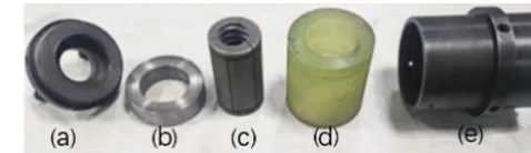
fac-(e)the housing.
tors on lapping. In this study, a new lapping method was de-veloped. In particular, a modified lapping tool was installed on a specially designed friction torque test machine, which can control the rotational speed and direction of a screw and monitor the friction torque applied on the screw dynamically. The effect of friction torque, rotational speed, abrasive par-ticulate size and lapping time were analyzed based on the results of a set of orthogonal experiments. The travel varia-tion, surface roughness and residual stress were measured to evaluate the lapping effect.
2 Details of the modified lapping method
2.1 The structure of the lapping tool
For manual lapping operations, a traditional 2-slit lapping tool is used. The traditional lapping tool has two main dis-advantages. Firstly, it demands specialized skills of the op-erator. In lapping a ball screw, high skills of the operator are definitely required, since the proper lapping condition partic-ularly the lapping pressure and speed depend on his continu-ous adjustment of the operation. Secondly, the conventional lapping tool has two slits. When the screw is tightened, the lapping tool can create only two contact areas on the work-piece as the lapping progresses, and the center of the tool cannot coincide with the center of the workpiece. It can only make the workpiece into an ellipsoidal shape and therefore, difficult to attain the desired shape of a screw.
The modified lapping tool is based on the theory estab-lished by Kyusojin et al. (1979, 1984). The theory assumes that a lapping tool, which has a cross section in the form of a regular polygon (withkangles), is used to lap a work-piece and the tool is in contact with the external surface of the workpiece. The workpiece’s radiusr(θ) is given by tangent polar coordinate and can be represented by Fourier series:
r(θ)=C0+C2cos (2θ+ϕ2)+. . .+Cncos (nθ+ϕn)+. . .
= ∞ X n=0
Cncos (nθ+ϕn) (1)
(whenϕ0=0, C1=0).
As shown in Fig. 1,liandli+1are two sides of the lapping
Figure 3.Detail drawing of the lapping nut.
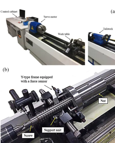
Figure 4.Friction torque test machine.
is the perpendicular ofli+1.Bi(xi, yi) is the intersection of li andli+1.G(xG, yG) is used to express the center of the
lapping tool when the tool rotates in contact with the exter-nal surface of the workpiece. Apparently, G(xG, yG) is the mean value ofBi(xi, yi). From Fig. 1,
oAi=r
θ+2π i k
(2)
lican be expressed as.
xcos
θ+2π i k
+ysin
θ+2π i
k
=r
θ+2π i k
(3)
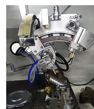
Figure 5.Installation method of the lapping tool.
The coordinates of point Bi can be obtained by using Eqs. (2) and (3). Thus,xGcan be obtained as
xG= 1 k
k X i=1
xi = 1 k
k X
i=1
∞ X n=0
Cn
cos
(n+1)θ+ϕn+
π(n+1) k +
2π(n+1)i
k
sinπ(1−n) k ÷sin
2π k
+cos
(n−1)θ+ϕn+
π(n−1) k +
2π(n−1)i k
sinπ(1+n) k ÷sin
2π k
(4)
when condition, n±1=mk (mis an integer), is satisfied, xG6=0. It means that the center of the lapping tool and the center of the workpiece are not coincident. The expressions ofxGandyGare given as follows:
xG= ∞ P n=0
Cncos [(n+1)θ+ϕn]
yG= ∞ P n=0
Cnsin [(n+1)θ+ϕn]
(n+1=mk) (5)
xG= ∞ P n=0
Cncos [(n−1)θ+ϕn]
yG= − ∞ P n=0
Cnsin [(n−1)θ+ϕn]
(n−1=mk) (6)
The theory shows that the center of the workpiece must coincide with the center of the lapping tool to reduce the vari-ation and increasing the number of slits is helpful. However, if the number of slits is too large, these two centers may be mismatched because of too much flexibility. Therefore, ac-cording to the reference and the lapping tool described by Guevarra et al. (2001), the new lapping tool has 6 slits and was designed to fit on the friction torque test machine.
Figure 6.Travel variation test machine.
Table 1.Details of the orthogonal experiments.
No. Friction torque Rotational speed Abrasive particulate Number of
(N×m) (rpm) size (mesh) round trips
1 1–1.5 10 600 6
2 1–1.5 30 800 12
3 1–1.5 50 1000 18
4 2–2.5 10 800 18
5 2–2.5 30 1000 6
6 2–2.5 50 600 12
7 3–3.5 10 1000 12
8 3–3.5 30 600 18
9 3–3.5 50 800 6
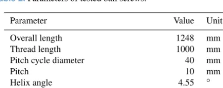
Table 2.Parameters of tested ball screws.
Parameter Value Unit
Overall length 1248 mm
Thread length 1000 mm
Pitch cycle diameter 40 mm
Pitch 10 mm
Helix angle 4.55 ◦
Raceway profile duplex circular arcs profile –
a polyurethane outer ring, a housing and a lapping nut. The part named lapping nut has 6 slits consisting of 3 slits on each side which were cut alternately at 120◦apart, as shown in Fig. 3. In order to prevent stress concentration, a through-hole was drilled in the end of each slit. This lapping tool has more contact areas on the screw to produce uniform lapping pressure from six directions, as compared to the conventional lapping tool which has only 2 slits. A polyurethane outer ring is used to cover the lapping nut. When the threaded end cover is screwed in the housing, the polyurethane outer ring will be compressed and provide stable friction torque during lap-ping. Changing the tightness of the end cover will change the friction torque applied on the screw.
2.2 The apparatus of the new lapping method
Figure 7.Travel variation indices.
3 Experimental method
A set of orthogonal experiments were designed to capture the effects of four main lapping factors: friction torque, abrasive particulate size, lapping time and the rotational speed of the screw. Details of each experiment are shown in Table 1. The lapping time was controlled by the number of round trips of the lapping tool. The lapping compound used was a mix-ture of green silicon carbide particulates and lubrication oil at about a volume ratio of 3:1. At the beginning of each lap-ping experiment, the compound was evenly brushed on the surface of the screw.
The travel variation, surface roughness, and residual stress were used to evaluate the lapping effect. Because it is very difficult to maintain the same travel variation among the screws during the test, even if they were acquired from the same manufacturer with the same process and size ters, we customized 20 ball screws with the same parame-ters from the same manufacturer (the main parameparame-ters of the tested ball screw are shown in Table 2). The travel variations of all 20 ball screws were measured before lapping, and then 9 ball screws were picked, of which the initial values were very close to each other. Each screw had a non-lapping sec-tion at the end. The length of the secsec-tion is 200 mm. The friction torque can be monitored by the test machine dynam-ically. When the fluctuation of friction torque exceeds the range of test parameter, the nut is considered to be worn out and will be replaced. When a lapping experiment was completed, the tested screw was cleaned and the travel varia-tion was measured and then, the screw was cut to get sample pieces. The length of sample pieces is 80 mm. Each screw had two groups of sample pieces. One was from the lapping section, and the other from the non-lapping section. These pieces were used to measure the surface roughness and
resid-Figure 8.The Taylor Hobson CCI(UK) white light interferometer.
ual stress. The surface roughness and residual stress of the pieces from the non-lapping section will be used as the ref-erence data in the subsequent analysis.
4 Experimental results and discussion
4.1 Travel variation
Tests to measure the travel variation were carried out on a ball screw test machine equipped with a circular grating and a linear grating. The structure of the test machine is shown in Fig. 6. The tested ball screw was fixed between the head-stock and the tailhead-stock. The spherical measuring head was placed in the screw raceway so that the air floating plat-form can move with the rotating screw. In travel variation measurement, there are three relevant indices (as shown in Fig. 7): the travel variation in a screw lead (V2π), which re-flects the short-period error; the travel variation in arbitrary 300 mm (V300), which reflects the long-period error; and the
6 2 (2–2.5 N×m) 3 (50 rpm) 1 (600 mesh) 2 (12 times) 8.13
7 3 (3–3.5 N×m) 1 (10 rpm) 3 (1000 mesh) 2 (12 times) 17.60
8 3 (3–3.5 N×m) 2 (30 rpm) 1 (600 mesh) 3 (18 times) 19.31
9 3 (3–3.5 N×m) 3 (50 rpm) 2 (800 mesh) 1 (6 times) 14.56
K1j 6.30 11.10 11.65 10.85
K2j 8.93 11.77 9.43 10.42
K3j 17.16 9.51 11.31 11.12
Rj 10.86 2.26 2.22 0.70
the gradual error. Comparing pulse signals measured from the circular grating and the linear grating determines these precision-related indices.
The indexVu is used in this study. Each screw was mea-sured three times. Table 3 shows the measurement results of the travel variation. The average of the three measurement re-sults of each screw was denoted byVuk(k=1∼9).Vu0
de-notes the average value before lapping. Four lapping factors including friction torque, rotational speed, abrasive particu-late size, and lapping time were numbered from 1 to 4 (de-noted byj,j=1∼4), respectively. Each factor takes three different values which were number from 1 to 3.K1jdenotes the sum ofVukof thejth factor under value 1. For example, K11=Vu1+Vu2+Vu3.K1jdenotes the average value ofK1j.
K1j= 1
3K1j(j =1∼4) (7)
The meanings ofK2j,K3j,K2jandK3jare similar toK1j andK1j.Rj denotes the difference between the maximum and minimum inK1j,K2j andK3j. The larger the value of Rj, the greater the impact of this factor on the travel variation after lapping.
As shown in Table 3, K11 is the minimum ofK11,K21
andK31. In addition,K11 andK21 are less thanVuo, while
K31 is much larger thanVuo, implying that a lower friction
torque can improve the travel variation of the screw. In the second column (j =2),K32is the minimum and is less than
Vuo.K22 is the maximum, andK12 is slightly smaller than
K22. The tested ball screws lapped under 50 rpm have the
smallest travel variation. In the third column (j=3), K23
is the minimum, while K13 andK33 are very close to each
other withK13slightly larger thanK33. The results show that
the 800 mesh abrasive particulates can result in the smallest travel variation. The three values in the fourth column (j=
Figure 9.X-ray stress measurement device.
4),K14,K24 andK34, are almost equal, of whichK24 is the
smallest, whileK14 is in the middle withK34 slightly larger
thanK14. In the last row of the table,R1 is the biggest of
the four numbersR1,R2,R3andR4, indicating that friction
torque has the greatest effect on travel variation.R2andR3
are almost equal and much less thanR1. Compared with the
friction torque, the rotational speed and abrasive particulate size have little effect on the resulted travel variation. AsR4
2 1 (1–1.5 N×m) 2 (30 rpm) 2 (800 mesh) 2 (12 times) 1.531
3 1 (1–1.5 N×m) 3 (50 rpm) 3 (1000 mesh) 3 (18 times) 1.115
4 2 (2–2.5 N×m) 1 (10 rpm) 2 (800 mesh) 3 (18 times) 3.382
5 2 (2–2.5 N×m) 2 (30 rpm) 3 (1000 mesh) 1 (6 times) 1.123
6 2 (2–2.5 N×m) 3 (50 rpm) 1 (600 mesh) 2 (12 times) 2.364
7 3 (3–3.5 N×m) 1 (10 rpm) 3 (1000 mesh) 2 (12 times) 3.220
8 3 (3–3.5 N×m) 2 (30 rpm) 1 (600 mesh) 3 (18 times) 3.151
9 3 (3–3.5 N×m) 3 (50 rpm) 2 (800 mesh) 1 (6 times) 2.904
K1j 1.283 2.602 2.240 1.744
K2j 2.290 1.935 2.606 2.372
K3j 3.092 2.128 1.819 2.549
Rj 1.809 0.667 0.787 0.805
Table 5.Surface roughness of right arc.
Lapping Friction torque Rotational speed Abrasive particulate size Number of round trips RaRk(µm)
factors j=1 j=2 j=3 j=4 RaR0=0.705
1 1 (1–1.5 N×m) 1 (10 rpm) 1 (600 mesh) 1 (6 times) 1.133
2 1 (1–1.5 N×m) 2 (30 rpm) 2 (800 mesh) 2 (12 times) 1.355
3 1 (1–1.5 N×m) 3 (50 rpm) 3 (1000 mesh) 3 (18 times) 1.190
4 2 (2–2.5 N×m) 1 (10 rpm) 2 (800 mesh) 3 (18 times) 3.138
5 2 (2–2.5 N×m) 2 (30 rpm) 3 (1000 mesh) 1 (6 times) 1.061
6 2 (2–2.5 N×m) 3 (50 rpm) 1 (600 mesh) 2 (12 times) 2.387
7 3 (3–3.5 N×m) 1 (10 rpm) 3 (1000 mesh) 2 (12 times) 3.364
8 3 (3–3.5 N×m) 2 (30 rpm) 1 (600 mesh) 3 (18 times) 3.182
9 3 (3–3.5 N×m) 3 (50 rpm) 2 (800 mesh) 1 (6 times) 2.808
K1j 1.226 2.545 2.234 1.667
K2j 2.195 1.866 2.434 2.369
K3j 3.118 2.128 1.872 2.503
Rj 1.892 0.679 0.562 0.836
4.2 Surface roughness
A Taylor Hobson CCI(UK) white light interferometer was used to measure the surface roughness, as shown in Fig. 8. Each sample piece of the tested screw after lapping has three roughness measurement points evenly distributed in the axial direction 120◦ apart. The left and right arcs of each point were measured. For the left arc, the average value of three points of each screw was denoted by RaLk(k=1∼9), and for the right arc, it was denoted by RaRk(k=1∼9).RaL0
andRaR0denote the average values of the left and right arcs
before lapping, respectively.
As shown in Table 4, all nine results, RaL1∼RaL9, are
bigger thanRaL0, indicating that the surface roughness
get-ting worse inevitably after lapping. Whatever experimental parameters were used, the surface roughness became worse.
In the first column (j=1),K11is the minimum, whileK21is
in the middle andK31is the largest. The increase in the
fric-tion torque increases the surface roughness. The results in the fourth column (j =4) is similar to the results in the first column.K14 is the minimum followed by K24, andK34 is
the largest. The increase of lapping time causes the increase of surface roughness. In the third column (j=3),K33 is the
minimum, whereK13 andK23are slightly bigger thanK33.
The smallest abrasive particulates do not make the surface roughness too bad. In the second column (j=2), the differ-ence amongK12,K22andK32is very small.K12andK32are
slightly larger thanK22. In the last row of the table,R1is the
biggest of the four. Similar to the results of travel variation, the friction torque has the greatest effect on the resulted sur-face roughness. The values ofR2,R3andR4are very close,
con-6 2 (2–2.5 N×m) 3 (50 rpm) 1 (600 mesh) 2 (12 times) −407.2
7 3 (3–3.5 N×m) 1 (10 rpm) 3 (1000 mesh) 2 (12 times) −280.8
8 3 (3–3.5 N×m) 2 (30 rpm) 1 (600mesh) 3 (18 times) −618.1
9 3 (3–3.5 N×m) 3 (50 rpm) 2 (800mesh) 1 (6 times) −334.0
K1j −267.0 −290.4 −436.9 −276.4
K2j −307.2 −366.8 −303.9 −320.3
K3j −411.0 −328.0 −244.4 −388.5
Rj 144.0 76.4 192.5 112.1
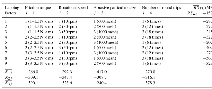
Table 7.Residual stress of right arc.
Lapping Friction torque Rotational speed Abrasive particulate size Number of round trips RSRk(MPa)
factors j=1 j=2 j=3 j=4 RSR0= −157.2
1 1 (1–1.5 N×m) 1 (10 rpm) 1 (600 mesh) 1 (6 times) −280.9
2 1 (1–1.5 N×m) 2 (30 rpm) 2 (800 mesh) 2 (12 times) −272.0
3 1 (1–1.5 N×m) 3 (50 rpm) 3 (1000 mesh) 3 (18 times) −245.1
4 2 (2–2.5 N×m) 1 (10 rpm) 2 (800 mesh) 3 (18 times) −322.2
5 2 (2–2.5 N×m) 2 (30 rpm) 3 (1000 mesh) 1 (6 times) −202.5
6 2 (2–2.5 N×m) 3 (50 rpm) 1 (600 mesh) 2 (12 times) −402.6
7 3 (3–3.5 N×m) 1 (10 rpm) 3 (1000 mesh) 2 (12 times) −273.7
8 3 (3–3.5 N×m) 2 (30 rpm) 1 (600 mesh) 3 (18 times) −567.6
9 3 (3–3.5 N×m) 3 (50 rpm) 2 (800 mesh) 1 (6 times) −329.0
K1j −266.0 −292.3 −417.0 −270.8
K2j −309.1 −347.4 −307.7 −316.1
K3j −390.1 −325.6 −240.4 −378.3
Rj 124.1 55.1 176.6 107.5
clusions can be obtained from the results of the right arc, except thatR3is the smallest of the four.
4.3 Residual stress
The X-ray stress measurement device, X-350A, was used to measure the surface residual stress, as shown in Fig. 9. The measurement points for residual stress were the same as for surface roughness. The left and right arcs of each point were measured. For the left arc, the average value of three points of each screw was denoted by RSLk(k=1∼9) and for the right arc, it was denoted byRSRk(k=1∼9).RSL0
andRSR0denote the average values of residual stress of the
left and right arcs before lapping, respectively.
As shown in Table 6. all nine results, RSL1∼RSL9, are
smaller thanRSL0. Moreover, they are less than zero, which
indicates that the surface of the sample was in compressive stress state. According to the references (El-Axir, 2002; Rech and Moisan, 2003; Segawa et al., 2004; Sasahara, 2005), a residual compressive stress improves component perfor-mance and life because it reduces working tensile stress and inhibits crack nucleation, whereas residual tensile stresses can significantly increase working stress, and leading to pre-mature failure of a component. Therefore, no matter what experimental parameters were used, the residual compres-sive stress of all samples was promoted. In the table,K11is
the minimum (absolute value) in the first column (j =1) and K31is the maximum, which indicates that the higher the
fric-tion torque, the higher the residual compressive stress is. The second column (j=2) showsK22is the maximum andK12
3 1
ond, andR2 is the smallest. Different from the conclusions
mentioned above, the abrasive particulate size has greater ef-fect on residual stress than friction torque or lapping time. The effect of the rotational speed is not as the important as the other three factors. The same conclusions can be obtained according to the results of the right arc.
5 Conclusions
In this study, a modified ball screw lapping method was pro-posed. The lapping tool was installed on a specially designed friction torque test machine. Compared with conventional lapping method, the lapping time of the present method was remarkably shortened, with only tens of minutes to get a good lapping result. Besides, this lapping method is more reliable as it doesn’t rely on operators’ experience and skills. The present method can help lower the labor cost and im-prove the efficiency of lapping.
Different values of lapping factors will bring about differ-ent lapping results. In this study, a set of orthogonal exper-iments was designed. The effects of lapping factors, includ-ing friction torque, rotational speed, abrasive particulate size and lapping time, were analyzed. The travel variation, sur-face roughness and residual stress of tested ball screws were measured to evaluate the lapping results. The following con-clusions were drawn from the experimental results:
1. The travel variations of some of the tested screws were improved whereas others became worse with differ-ent lapping parameters. The surface roughness became worse no matter what experimental parameters were used. The results of residual stress of all nine ball screws were less than zero and higher than the initial com-pressive residual stress in magnitude, implying that the residual compressive stress was enhanced in each screw.
2. As shown in Table 3,R1is much bigger than the other
three, and therefore friction torque has the greatest ef-fect on travel variation. The increase in the friction torque increases the travel variation of the screw. Com-pared with the friction torque, the rotational speed and abrasive particulate size have secondary effect on travel variation, whilst the effect of lapping time is negligible. If only the travel variation is concerned, the best com-bination of lapping parameters is 1–1.5 N×m, 50 rpm, 800 mesh and 12 round trips.
Similar to the results of travel variation, the friction torque has a dominant effect on the surface rough-ness, while the rotational speed, abrasive particulate size
The abrasive particulate size has the greatest effect on residual stress, while the friction torque is the second and the lapping time is the third. The bigger the abrasive particulates, the higher the residual compressive stress is. Further, increasing the friction torque and lapping time can also improve the residual compressive stress. The influence of rotational speed is much less than the other three. If only the residual stress is concerned, the best combination of lapping parameters is 3–3.5 N×m, 30 rpm, 600 mesh and 18 round trips.
3. The friction torque has much larger effect on travel vari-ation and surface roughness than the other factors. In particular, the increase in friction torque causes signifi-cant increase in travel variation of the screw and there-fore, the optimum value of the friction torque is 1– 1.5 N×m in order to minimize travel variation.
The rotational speed is not an important factor for travel variation, surface roughness and residual stress.
The abrasive particulate size has the greatest effect on residual stress. The 600 mesh abrasive particulates can significantly improve the residual compressive stress. Although 600 mesh is not the best choice for travel variation and surface roughness, the abrasive particu-late size is not an important factor for them. Therefore, 600 mesh is suggested as the best particulate size for lapping.
The longer the lapping time, the worse the surface roughness is, whereas although a long time lapping pro-cess can improve the residual stress. Given that the lap-ping time is more important for residual stress rather than for surface roughness, and the surface roughness can be improved by subsequent processing, 18 round trips is suggested as the best choice for lapping.
Data availability. No data sets were used in this article.
Author contributions. ZL, FH and JJ designed the modified lap-ping method and the laplap-ping tool; ZL and JJ designed and carried out experiments; ZL and JJ collected and analyzed experimental results; ZL wrote the manuscript with contributions from all co-authors.
References
El-Axir, M. H.: A method of modeling residual stress distribution in turning for different materials, Int. J. Mach. Tool. Manu., 42, 1055–1063, https://doi.org/10.1016/s0890-6955(02)00031-7, 2002.
Guevarra, D. S., Kyusojin, A., Isobe, H., and Kaneko, Y.: De-velopment of a new lapping method for high precision ball screw (1st, report)-feasibility study of a prototyped lapping tool for automatic lapping process, Precis. Eng., 25, 63–69, https://doi.org/10.1016/s0141-6359(00)00059-3, 2001.
Guevarra, D. S., Kyusojin, A., Isobe, H., and Kaneko, Y.: De-velopment of a new lapping method for high precision ball screw (2nd report): Design and experimental study of an auto-matic lapping machine with in-process torque monitoring sys-tem, Precis. Eng., 26, 389–395, https://doi.org/10.1016/s0141-6359(02)00122-8, 2002.
Kyusojin, A. and Inada, H.: Lapping high precision polygo-nal shafts, Precis. Eng., 6, 3–8, https://doi.org/10.1016/0141-6359(84)90064-3, 1984.
of 0.45 % C steel, Int. J. Mach. Tool. Manu., 45, 131–136, https://doi.org/10.1016/j.ijmachtools.2004.08.002, 2005. Segawa, T., Sasahara, H., and Tsutsumi, M.: Development of a
new tool to generate compressive residual stress within a ma-chined surface, Int. J. Mach. Tool. Manu., 44, 1215–1221, https://doi.org/10.1016/j.ijmachtools.2004.03.010, 2004. Verl, A., Frey, S., and Heinze, T.: Double nut ball screw with
improved operating characteristics, CIRP Ann., 63, 361–364, https://doi.org/10.1016/j.cirp.2014.03.128, 2014.
Wei, C. C. and Lai, R. S.: Kinematical analyses and trans-mission efficiency of a preloaded ball screw operating at high rotational speeds, Mech. Mach. Theory, 46, 880–898, https://doi.org/10.1016/j.mechmachtheory.2011.02.009, 2011. Wei, C. C. and Lin, J. F.: Kinematic analysis of the ball