Modelling and Analysis of a Multi-Storey
Building using RFEM
Rohini. B Shanmukha Ch.
Assistant Professor B. Tech. Student
Department of Civil Engineering Department of Civil Engineering
R.G.M.C.E.T, Nandyal, Andhra Pradesh, India R.G.M.C.E.T, Nandyal, Andhra Pradesh, India
Abstract
Rapid progress in population calls for the increase in necessity of structures for living. Under the changed circumstances, the vertical growth of buildings i.e. constructions of multi-storeyed buildings has become inevitable both for residential and as well as office purposes. In order to compete in the ever growing competent market it is very important for a structural engineer to save time. as a sequel to this an attempt is made to analyze and design a Multi-storeyed building by using a software package RFEM. Many leading software like STAAD-PRO, AUTOCAD, ETABS, RFEM, RX-TIMBER, etc. are available in the market used vividly for their project design purpose .With the objective to fulfil the above, the existing Mechanical block, RGMCET is chosen for the study. Only the superstructure is analysed neglecting the effect of seismic forces. The results obtained from RFEM agree with the results from Kani’s method.
Keywords: Multi-Storey Buildings, Softwares, Analyze, Design, RFEM, Kani’s Method
________________________________________________________________________________________________________
I. INTRODUCTION TO RFEM (R-FINITE ELEMENT METHOD)
RFEM is a powerful 3D FEA program helping structural engineers to meet requirements in modern civil engineering. The RFEM program family is based on a modular system. Mainly RFEM is used to define structures, materials and loads for planar and spatial structural systems consisting of plates, walls, shells and members. It is also possible to create combined structures as well as modelling solid and contact elements.
The modular approach allows you to combine all programs individually according to your needs. Upgrades at a later time are always possible. RFEM offers numerous interfaces representing as the perfect tool as smooth interaction between CAD and structural analysis in Building Information Modelling (BIM).
Features of Graphical User Interface of RFEM
Intuitive Graphical User Interface
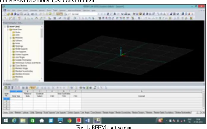
1) The Start screen of RFEM resembles CAD environment.
Fig. 1: RFEM start screen
Display Control of Objects Global Unit Control
Incremental Load Application
Multi-Core Processor and 64-Bit Technology
Comparison Study- Kani’s Method and RFEM
A simple frame shown in Fig. 2 is analyzed using Kani’s method. The table 1 shows the comparison between the results obtained from Kani’s method and RFEM. It is observed that the variation is approximately within 5%.
Fig. 2: Frame considered for comparative study [1]
Fig. 3: Model of frame in RFEM
Table - 1 Comparative study
Sl.no Members Bending Moments (in kNm) % error Kani’s method RFEM
1 AB +42.35 +43.20 2.00
2 BA +84.70 +87.64 3.47
3 BE -232.94 -237.95 2.15
4 BC +148.23 150.31 1.40
5 CB +169.41 173.70 2.53
6 CD -169.40 -173.70 2.53
7 DC +455.30 444.57 2.35
8 DG +169.40 173.70 2.53
9 EB +423.53 415.40 1.91
10 EH -423.53 -415.40 1.91
11 GD +169.40 173.70 2.53
13 HG -148.23 148.23 0
14 HE +234.94 237.95 2.15
15 HJ -84.70 87.64 3.47
16 JH -42.35 -43.20 2.00
II. PLAN OF BUILDING CONSIDERED FOR THE ANALYSIS
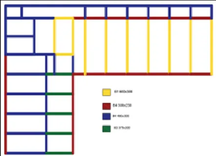
The structure chosen to be analysed is G+3 institution building. The plan of the building is shown below. It is an existing building, Mechanical Block in RGMCET, Nandyal.
Fig. 4: Plan of the building including dimensions of columns in mm.
Structure Specifications
3 lecture halls in each floors (8.52 X 10.35)m Storeroom (2.44X10.35)m
Stairs (6.7X3.75)m Staffroom (3.65X3.75)m Washroom (3.35X5.8)m Staffroom (3.35X5.8)m Lecture hall 1(8.23X18.65)m Lecture hall 2(14.6X5.38)m Corridor (41.60X2.3)m
Dimensions are considered as per the centre line of the wall Location of Beams and Dimensions
Fig. 5: Location of beams and all dimensions are in mm
Calculation of Loads
Masonry load
Wall load=height of the wall X width X Density of masonry material For beam,
B1 (3.6-0.6)X0.30X18.85X1=16.965kN/m2
B2 (3.6-0.3)X0.28X18.85X1=14.310 kN/m2
B3 (3.6-0.45)X0.30X18.85X1=17.813kN/m2
B4 (3.6-0.375)X0.30X18.85X1=18.2373kN/m2
On corridor beams ,
1.17 X 0.23 X 18.85=5.10kN/m2
Live Loads
As per IS 875 part II Lecture halls 3kN/m2
Corridor 4kN/m2
Laboratory 3kN/m2
Stairs 5kN/m2
Staff room 2.5kN/m2
Wash room 2kN/m2
Wind loadS
Wind loads as per IS 875 part III
Basic wind speed at the location of building: 39 m/s Design wind load (as per IS 875 part iii, Clause 5.3)
Vz= Vbk1k2 k3k4,
The wind pressure at any height above mean ground level shall be obtained by the following relationship between wind pressure and wind speed:
Pz= 0.6 Vz2
Pz = wind pressure in N/m2 at height z, and
Vz= design wind speed in m/s at height z.
The design wind pressure pd can be obtained as,
Pd = Kd. Ka. Kc. KZ
Where Kd = Wind directionality factor = 0.9\
Ka = Area averaging factor = 0.9
Kc = Combination factor = 1
Pd= 0.8146 kN/m2
This is multiplied with the area surrounding the joint that is exposed to the wind load.
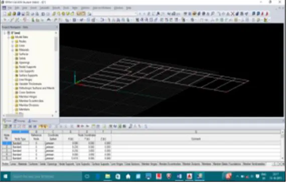
III. MODELLING OF STRUCTURE
Importing Plan from AutoCAD to RFEM
Open RFEM software, make sure that your line plan of building is pre drawn in AUTOCAD software. Click on File menu > Import, mark Autodesk AUTOCAD and then click OK.
It is possible to change the coordinates of line plan while importing.
Geometry and Material
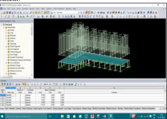
Now click on Node icon in the insert ribbon and place nodes where ever the columns need to be erected.
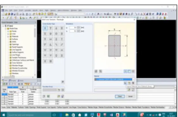
Now click on New single member in the insert ribbon, select member type as beam or compression member based on model data
In the new single member dialogue box select the member cross-section software aids for the creation of own cross-section or import from standard library cross-section data.
Select the type of cross-section and click ok then enter the geometry of the member and click OK.
Fig. 7: Importing cross section geometry data from library
Fig. 8: Importing material data from material library
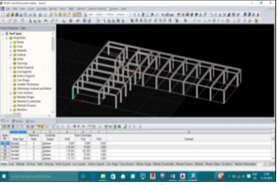
Erecting Column in RFEM
After click ok in the single member dialogue box you will get a column creation cursor Join the nodes to create column.
Fig. 9: Erecting columns in RFEM
Creation of the Beams
Select single member in the insert ribbon > material type as beam > select import from cross sectional library > select beam > cross-section > give dimensions of the beam and then select material depending upon design requirements
Then a beam cursor will appear on the screen join the nodes for creating the beam between the nodes.
Fig. 10: Creation of beams
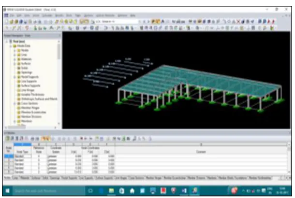
Creating the Slabs
Select the new rectangular surface in the insert ribbon > give material type > thickness and click OK. Surface creation cursor will appear join the nodes of the required surface.
Surface will appear on the columns and beams.
Giving supports to the column
Select new nodal support in the insert ribbon and select the type of support > place it where ever necessary in the project.
Fig. 12: Giving supports to column
IV. LOAD COMBINATION AND ASSIGNING OF LOADS
Creation of loads
Member Load
Go to new member load in the insert ribbon and click on it Select load type
Load distribution Load direction
Enter the value of load parameter.
Fig. 13: Assigning loads to members
Surface Load
New surface load in the insert ribbon Select load type
Load distribution Load direction
Fig. 14: Creation of new surface load
Wind Load
Wind load can be assigned as UDL over an exposed surface or nodal load assigned at the exposed node. In the current project nodal loads are assigned.
New nodal load in the insert ribbon Select the node or enter node number Give the value of load
Click OK.
Fig. 15: Wind forces acting in +X direction
Assigning the Loads
The different loads created are assigned respectively. Creation of Load Combinations
Load combination are created as per IS 875:2000 part 5
DL
DL+IL DL+IL+ WL
DL = dead load, IL = imposed load, WL = wind load
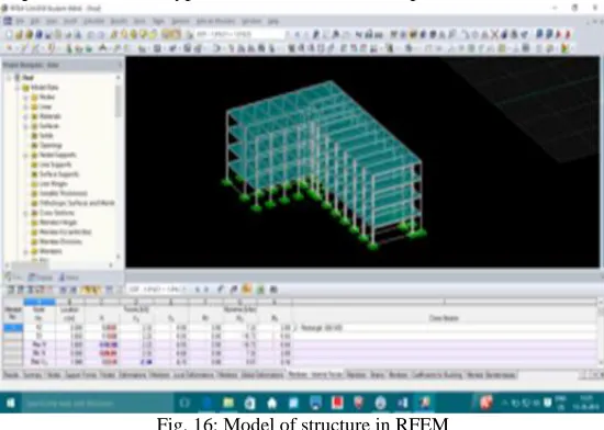
V. ANALYSIS OF THE STRUCTURE
Steps involved in analysis of structure in RFEM
In order to check the variation in bending moment, structure is analysed in RFEM as follows:
Select calculations parameters in the results ribbon and enter all the required parameters in the dialogue box. Then click on calculate all icon in the results ribbon.
The software package will analyse the structure and gives the results of the members and surfaces. In order to see the results right click on the member select “Results diagram”
The results will appear in the dialogue box you can view all the loads and load combinations.
Exporting Report
Go to file > select export report > select the type of the file that to be exported and click ok.
Fig. 16: Model of structure in RFEM
VI. MANUAL ANALYSIS (KANI’S METHOD)
To elaborate this method we have considered Y5 frame to analyse.
Fig. 17: Frame Y5 showing members and joint notations
Sequence of steps to be followed
Step 1: Rotation contributions
Sum of the restrained moment of a joint and all rotation contributions of the far ends of members meeting at that joint is multiplied by respective rotation factors to get the required near end rotation contribution.
For the first cycle when far end contributions are not known, they may be taken as zero (Ist approximation).
By repeated application of this calculation procedure and proceeding from joint to joint in an arbitrary sequence but in a specific direction, all rotation contributions are known.
The process is usually stopped when end moment values converge Table - 1
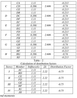
Calculation of rotation factors
Joint Member Stiffness (k) Ʃk Rotation Factor
A AB 0.368 1.496 -0.129
AC 1.11 -0.371
B BA 0.368 1.496 -0.129
C
CA 1.11
2.606
-0.213
CD 0.386 -0.74
CE 1.11 -0.213
D
DB 1.11
2.606
-0.213
DC 0.386 -0.74
DF 1.11 -0.213
E
EC 1.11
2.606
-0.213
EF 0.386 -0.74
EG 1.11 -0.213
F
FD 1.11
2.606
-0.213
FE 0.386 -0.74
FH 1.11 -0.213
G
GE 1.11
2.606
-0.213
GH 0.386 -0.74
GI 1.11 -0.213
H
HF 1.11
2.606
-0.213
HG 0.386 -0.74
HJ 1.11 -0.213
Table - 2
Calculation of distribution factors
Storey Member Stiffness(k) Ʃk Distribution Factor
I AC 1.11 2.22 -0.75
BD 1.11
II CE 1.11 2.22 -0.75
FD 1.11
III GE 1.11 2.22 -0.75
HF 1.11
IV IG 1.11 2.22 -0.75
JH 1.11
Step 2: Calculation of Fixed end moments Step 3: Calculation of Final End Moments
Rules for the Calculation of final end moments (side sway cases)
For beams, End moment = FEM + 2 near end contribution + Far end contributions.
For columns, End moment. = FEM + 2 near end contribution + Far end contribution + linear displacement contribution of that column for the latest cycle.
Table - 3 Final end moments.
Member Fixed End Moment (in kNm)
Near End Contribution (in kNm)
Far End Contribution (in kNm)
Final End Moment (in kNm)
AB -350.42 45.21 -42.17 -302.17
BA 350.42 -42.17 45.21 311.29
CD -424.69 22.43 -14.81 -394.64
DC 424.69 -14.81 22.43 417.5
EF -424.69 30.89 -15.41 -378.32
FE 424.69 -15.41 30.89 424.76
GH -424.69 39.19 -18.24 -364.55
HG 424.69 -18.24 39.19 427.4
AC 0 130.02 64.57 324.61
CA 0 64.57 130.02 259.16
BD 0 -121.3 -42.63 -285.23
DB 0 -42.63 -121.3 -206.56
CE 0 64.57 88.9 218.04
EC 0 88.9 64.57 242.37
DF 0 -42.63 -44.37 -129.63
FD 0 -44.37 -42.63 -131.37
EG 0 88.9 112.81 290.61
GE 0 112.81 88.9 314.52
FH 0 -44.37 -52.49 -141.23
HF 0 -52.49 -44.37 -149.35
GI 0 112.81 0 225.62
IG 0 0 112.81 112.81
HJ 0 -52.49 0 -104.98
VII.RESULTS AND DISCUSSIONS
Results obtained from both manual analysis and RFEM are compared. The following tables show the comparison of results. Note: Sign convention in RFEM is different from manual analysis. Clockwise moments are taken as positive for Kani’ s method where as they were considered negative in RFEM .To avoid confusion, the final moments from Kani’s method are expressed with the same sign convention as considered in RFEM.
This is the frame considered initially for showing the calculation of Rotation factors and distribution factors.
Fig. 20: Beam and Node numbers of Frame Y5
Table - 4 FEM of beams of Y5 frame Beams RFEM Kani's method
638 250.98 302.17
264.84 -311.29
509 350.76 394.64
343.76 417.5
515 345.53 378.32
344.32 -424.76
273 336.9 364.55
344.18 -427.4 Table - 5
FEM of columns of Y5 frame Columns REFM Kani's method
568 191.17 -292.46
257.36 -225.21
567 195.82 315.58
236.29 236.91
439 172.27 -136.13
163.82 -148.65
438 320.11 199.73
310.35 201.47
311 198.63 -178.22
183.35 -202.13
310 182.50 253.62
176.50 261.74
51 68.42 -133.13
147.72 -20.32
50 63.79 197.47
130.32 144.98
VIII. CONCLUSIONS
In this paper, analysis of a multi- storey building is done using RFEM and Kani’s method and the results obtained from both methods have been compared and the results found to agree with each other.
Using RFEM the analysis of the multi- storied building completed much quicker when compared to analysis using Kani’s method.
The variation is negligible for the members for less final end moments but was significant where final moments are higher. The end moments obtained from Kani’s method are higher than those obtained from RFEM.
REFERENCES
[1] Ramamrutham, “Theory of structures” ,Third edition [2] Indian codes referred:
IS 875: Code of Practice for Design Loads (Other than Earthquake) for Building and Structures,
IS 875: Part 1 Dead Loads – Unit Weights of Building Materials and Stored Materials, Bureau of Indian Standards, Eighth Reprint Sept. 2003, 37 pages. IS 875: Part 2 Imposed Loads, Bureau of Indian Standards, Sixth Reprint June 1998, 18 pages
![Fig. 2: Frame considered for comparative study [1]](https://thumb-us.123doks.com/thumbv2/123dok_us/7805724.1661485/2.612.139.485.134.759/fig-frame-considered-comparative-study.webp)