ISSN (Online): 2320-9364, ISSN (Print): 2320-9356
www.ijres.org Volume 3 Issue 7 ǁ July 2015 ǁ PP.08-14
Development and Implementation of a Washout Algorithm for a
6-dof Motion Platform of Flight Simulator
Wu Jiang
1, He Fajiang
21
(School of Mechanical Engineering, Shanghai University of Engineering Science, Shanghai 201620, China)
2(School of Air Transportation, Shanghai University of Engineering Science, Shanghai 201620,China)
Corresponding author: He Fajiang
ABSTRACT
: Flight simulators for pilot training is extremely important due safety and economic factors. Flight simulator needs to simulate different kinds of complicated motion state such as roll, pitch and yaw angles. It has six-degree of freedom, high precision, high rigid, modular design and many other advantages. The motion system responds to the aircraft linear and angular accelerations in order to compute the most appropriate cabin motion to replicate these accelerations, subject to the displacement limits and the velocity limits of the actuators. The cabin accelerations are filtered in order to compute the most appropriate cabin motion to replicate the actual airplane accelerations. This paper developed and implemented a motion washout algorithm that can enhance the fidelity of motion platform and the cabin motion never exceeds the mechanical limits of the motion platform, particularly the maximum actuator displacements and the maximum actuator velocities.Keywords
: Motion washout algorithm, Flight Simulator, 6-dof motion platform, Simulation fidelityI.
INTRODUCTION
Currently, parallel motion platform has been studied and applied widely result from its advantages in terms of rigidity, accuracy, simple structure and ability of large load bearing. Lots of various advantages have been discussed in the research literature [1]. Because of its obvious asset the 6-dof parallel motion platform has been used on flight simulator. A flight simulator has two most important functions, one is flight training the other is research and development [2]. A flight simulator must provide linear motion along the three axis and angular motion around the three axes of the plane to the pilot. The 6-dof parallel motion platform will make the motion such as pitching, yawing, rolling, acceleration, deceleration, and even turbulence, so it can simulate the motion of a real plane.
Motion washout algorithm [3] can limit motion range of a flight simulator within a physical limitation of the 6-dof parallel motion platform. This paper proposed a novel motion washout algorithm that can accurately transform aircraft specific force into flight simulator platform motions at high fidelity within the flight simulator’s physical limitations.
It is important to design reasonable washout algorithms to replicate real aircraft sensations for pilots in limited space as accurately as possible. In this paper we developed and implemented washout algorithm, the results present the washout algorithm can improve the fidelity of flight simulator motion platform effectively.
II.
6-DOF
PARALLEL
MOTION
PLATFORM
Compared to series platforms,6-dof parallel motion platform offer the advantages of high stiffness, speed capability, precision, low inertia at the expense of smaller workspace and ability to bear large loads [4]. So the 6-dof parallel motion platform have been used in military, industry and recreation result from its virtues.
Flight simulator is used to simulate the actual airplane on the ground. As an important part of flight simulator, the performance of the 6-dof parallel motion platform will directly affect the fidelity of flight simulation. Flight simulator with 6-dof parallel motion platform have the main outstanding virtues in reducing training costs, risks and improving training efficiency [5].
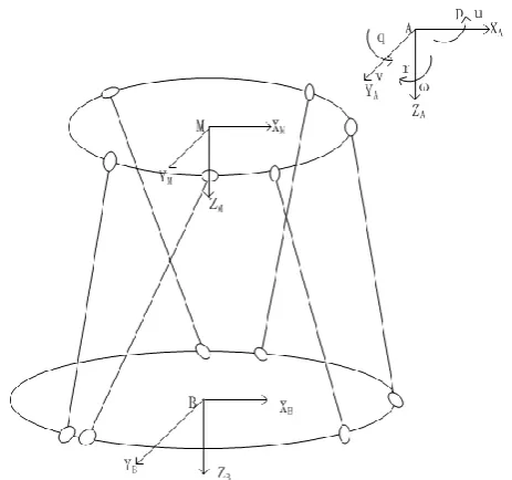
Fig -1: Schematic view of the 6-dof parallel motion platform
2.1 The Coordinate of 6-dof Parallel Motion Platform
Fig -2: Frame assignment for the 6-dof parallel motion platform
The coordinate systems of 6-dof parallel motion platform has been constructed and illustrated in figure 2. The {B} coordinate system is the base coordinate system fixed to the base platform, the origin B of {B} is the geometry center of base platform, while the {M} is attached to the moving platform , the origin M of {M} is also the geometry center of moving platform. And cockpit systems coordinate is {A} with an origin A at the centroid of the cockpit. We assume the center of the vestibular system isfixed to the origin of cockpit systems coordinate in order to simplify calculation. All axes will be assumed to be orthogonal right hand axes, that is, positive forwards, positive right and positive down as shows in figure 2.
2.2 Translation Between Frames
The motion platform system needs to respond to the linear and angular accelerations like a real plane. The cockpit accelerations aretransformed from the centroid of flight simulator cockpit to the pilot position and finally to the base frame in order to compute the actuator lengths. The cockpit accelerations and displacement of moving platform are filtered sothat the moving platform motion never go beyond themaximum actuator displacements and the maximum actuator velocities.
Z-Y-X Euler angle is used to express the rotation matrix R from {A} to {B}.The linear velocities are u, v and w; the angular velocities are p, q and r about the response x, y and z axes. Cockpit orientation about the
cockpit systems coordinate can be defined as three angles, the path angle
, the roll angle
and the yaw anglec c
c s s
s c
c s c
s s
R
s c
c c
s s s
s s c
c s
s
c s
c c
(1)
Where, c=cos, s=sin.
We need to translate the acceleration of A to the acceleration of B, is given by the transformation:
b
a
R a
(2) Wherea
b
is the acceleration of B and
a
is the acceleration of A.
Cockpit orientation can be defined with respect to base coordinate, providing three angles, the path angle
B
, the roll angle
Band the yaw angle
B. The cockpit rates are given by:1
0
sin
0
cos
cos sin
0
sin
cos cos
B B B
p
q
r
(3)
The reverse transformation, to derive the Euler angle rates
Bfrom the cockpit rates, is given bythetransformation:
1
sin tan
cos tan
0
cos
sin
0
sin sec
cos sec
B B B
p
q
r
(4)
III. SIMULATIONANDIMPLEMENTATIONOFAMOTIONSYSTEM
Acceleration sensation, linear and angular motion are provided by actuators attached between the moving platform and base platform. By providing strong initial motion sensation, the pilot is response to the change of velocity and acceleration. The wash-out filters can remove accelerations and restore the moving platform displacement to neutral position. Because of the mechanical limits of the motion platform, particularly the maximum actuator displacements and the maximum actuator velocities the motion platform needs to go back to the initial state after completing a flight behavior ,so that it is positioned to generate new motion sensations.
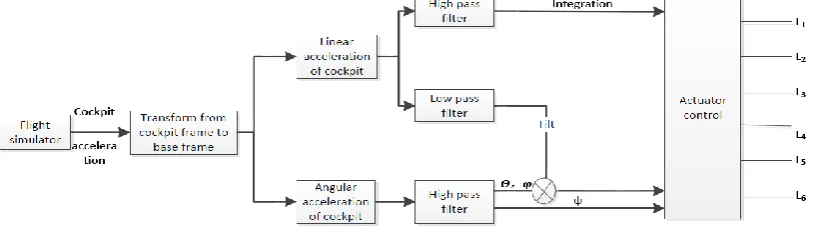
Fig -3: Schematic diagram of the motion washout algorithm
Figure 3 shows the schematic principle of motion washout algorithm. The high-pass filter responds to sudden changes to provide onset sensations as linear accelerations,but this motion reach the limits quickly. Sustained motion is represented through tilting the cabin that offers the gravitational acceleration vector. The relatively slow cabin motion as angular accelerations is achieved by thelow-pass filter.
3.1 The Washout Algorithm
The three-order form of high-pass filter for acceleration is given by 2 1 2 2 1
2
hi n n
x
k s
s
x
s
s
s
(5)Where
x
iis the input position,x
his the output position,
is the damping ratio,2
ncorresponds to the viscousdamping of the actuator.
The two-order form of low-pass filter for angular velocity is given by
2
2 2
2
2arctan
i
x
k
s
s
g
(6)
1
k
andk
2are proportionality coefficient. We chose x axes direction to simulation and the value of different parameters are decided by debugging the motion washout algorithm repeatedly. Table 1 shows the value of algorithm parameters.Table 1 parameters of washout algorithm Parameters
1
k
k
2
hx
hx
lx
lxValues 0.9 0.9 1 2.6 1 5
3.2 Simulation and Analysis
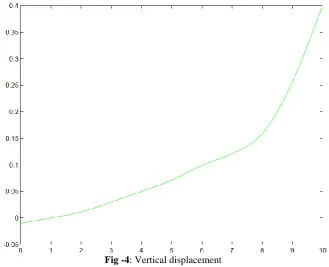
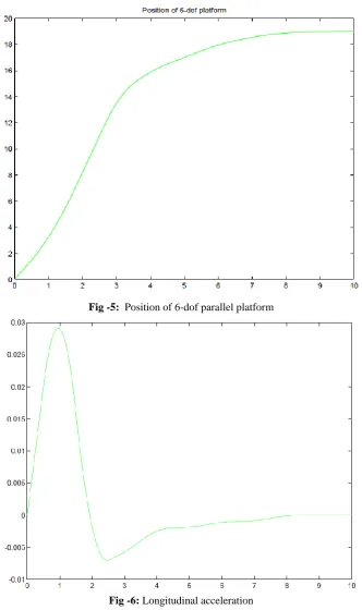
The effect of a high-pass filter on the platform motion is shown in Figure 4 to 6. Figure 4 is the vertical displacements. The toptrace shows vertical displacement of the cockpit which simulated an aircraft from horizontal flight to climb up.Figure 6 shows themoving platform longitudinal acceleration. The initial acceleration reaches 0.03 g before it is washed out. The longitudinal acceleration is washed out to zero without any sensations which proved the washout algorithm is effective. Themoving platform displacement is approximately 19 in before it is washed out to zero as shown in figure 5. Notice that the moving platform does not exceed its limitsof acceleration respectively, in the longitudinalaxis. In fact, a higher-order filter is likely to be used to improve the response.
The motion system response with a low-pass filter is shown in Figure 7 and 8, for an applied yaw angular velocityincreasing to 15 deg/sec after approximately 10 s. Figure 7 trace shows the yaw angular velocity through low pass filter and figure 8 trace shows yaw angle through low pass filter of the moving platform.
Fig -5: Position of 6-dof parallel platform
Fig -7:Yaw angular velocity through low pass filter
Fig -8: Yaw angle through low pass filter
IV. CONCLUSIONS
REFERENCES
[1] Gao Z, Zhang D, Ge Y. Design optimization of a spatial six degree-of-freedom parallel manipulator based on artificial intelligence approaches. Robotics and Computer-Integrated Manufacturing 28(4), 2010, 484-92.
[2] Ki Sung You, Min Cheol Lee, Euggene Kang, Wan Suk Yoo, Development of a Washout Algorithm for a Vehicle Driving Simulator Using New Tilt Coordination and Return Mode. Journal of Mechanical Science and Technology 19(1), 2005,272-282. [3] Grant, P.R., Reid, L.D.: Motion washout filter tuning: Rules and requirements. Journal ofAircraft 1997, 34(2), 145–151 [4] Gianmarc Coppola, DanZhang, KefuLiu b. A 6-DOF reconfigurable hybrid parallel manipulator. Robotics and
Computer-Integrated Manufacturing 30, 2014, 99-106.