ISSN (Online): 2320-9364, ISSN (Print): 2320-9356
www.ijres.org Volume 7 Issue 1Series I ǁ 2019 ǁ PP. 18-25
Optimum Design and Performance Evaluation of a Micro-Bubble
Generator
*1
Jiafeng Yao,
1Li Wang,
1Zifei Xu
*1College of Mechanical and Electrical Engineering, Nanjing University of Aeronautics and Astronautics,
Nanjing, China
Corresponding Author:JiafengYao,
ABSTRACT:
Optimal design and performance analysis of a microbubble generator were carried out for the application of a protein skimmer. Four different shapes of orifice used in a micro-bubble generator were designed and analyzed. Concentric orifice was designed and used in our study. Moreover, in order to get the optimum design, numerical simulations of the pressure loss in Four Venturi-type and four Sadatomi-type micro-bubble generators were carried out, respectively. Through the simulations and the analysis, Venturi-type "VMBG1" microbubble generator has the best performance due to its largest pressure drop among them.The new micro bubble generator which use the designed concentric orifice and Venturi-type construction would allow to increase the efficiency and the productivity of the protein skimmer.KEYWORDS:
Micro-bubble generator, Two-phase flow,Orifice, Simulation, Pressure drop--- Date of Submission: 20-02-2019 Date of acceptance: 08-03-2019
--- ---
I.
INTRODUCTION
A protein skimmer is widely used in aquariums and in reef tanks to purify and aerate water. By using this device, we can successfully remove the organic materials and food particles, which are mainly generated by fish feeding and excretions of living organisms inside the reef system [1]. Several types of protein skimmers are available in the market today. Each type does the pretty much same task.
A protein skimmer consists of three main parts, a water pump, a reaction chamber and a collection cup. The water/air interface is generated inside the water pump. The water is flowing through a Venturi valve. Due to the big pressure drop inside the valve, the air is sucked into the valve, and then a multiphase flow is formed. After that, the multiphase flow furthermore passes through a special equipment known as the needle wheel impeller. The purpose of it is to break the air in the pipe into smaller air bubbles. The main purpose of performing this task is to increase the contact area of the water/air interface to maximize the efficiency of the water purification process. Later the multiphase flow is carried to a reaction chamber where the air bubbles contact with the minute materials in the water and perform the reaction [2].
Micro bubbles with larger size are created inside the needle wheel impeller, which directly affects the efficiency of the protein skimmer. Because larger micro bubbles decrease the contact surface of the bubbles, it decreases the efficiency of the chemical reactions in the water purification process. In addition, the technology is also a bit of over dated. We have not experienced any type of significant changes to its design or any advanced developments applied to these protein skimmers. The first-generation protein skimmers used the needle wheel impeller to create micro bubbles and still it uses the same exact methods to generate the micro bubbles.
The other major disadvantage is the less life expectancy of the water pump. For a single protein skimmer, a water pump needs to be replaced with because the water pump suddenly stops functioning properly. This led to a huge destruction inside the sea water tanks. Because without the water pump the protein skimmer is not capable of functioning at all.
Also these protein skimmers are only can be operated in salt water systems and not capable of operating in fresh water systems. Because the sea water is much denser than the fresh water. The higher surface tension delivered by the salt water allows the micro bubbles to stay smaller than in the fresh water. So if place a protein skimmer inside a fresh water tank system, we cannot expect the exact same results as in the salt water system. The results will be always inferior to the sea water systems results [3].
On the other hand, this design will allow this device to be also used in fresh water. Due to the minute structure and size of the micro bubbles generated inside the system, the surface tension of fresh water would not become a barrier for the operations. That will allow to use it in both fresh and sea water tank systems [4].
In the present study, we have confirmed that the appropriate micro bubble design type for our micro bubble generator is the Venturi-type micro bubble generator. When discussing further about the Venturi-type micro bubble generators we come across with several designs which lies under the Venturi-type generators. Among them, the generators which are produced using orifice plate and the generator replacing the traditional orifice with a solid ball are the most famous [5]. In this paper we plan to find out which type has the best performance among these micro bubble generators.
II.
DESIGN OF A MICRO BUBBLE GENERATOR
A. Orifice design
There are two main identified types of fluid meters. The one is "Positive displacement type" which measures the quantity, the other one is known as "Inferential type" which measures the rate of flow. For the inferential flow meter type there are two main sub types which are known as the "orifice plates" and "flow nozzles" or Venturi tubes.
An orifice is an object which is not only used in scientific experiments but also used in our daily life [6]. An orifice plate is a flat plate made out of a certain metal with a hole which is machined or grilled through the metal plate placed between a pipe. When a certain type of flow with a specific pressure or with a given velocity passes through this orifice plate, it will lead to a pressure difference across the two sides of the orifice hole. There are specific requirements and qualities which we have to consider when manufacturing these orifice plates. Those requirements are the surface condition of the upstream face of the plate, Edge sharpness, Plate thickness and orifice thickness. Orifice plates are the most often used flow meter type in the world. By using orifice meters, we can gain many advantages. Orifice plates have been proved that they are much more effective and reliable than the other means of flow meters for years. Regarding the orifice plate we can obtain three main advantages which are as follows: (a) to create a pressure difference/pressure loss, (b) to measure the flow rate, (c) to restrict a certain flow.
The pressure decreases when the fluid travel through the hole of orifice plate, while the velocity of the fluid is increased as the pressure of the liquid decreases. It works under the Bernoulli’s principle which shows the relationship between the velocity of a certain fluid and the pressure of that fluid as the pressure decreases the velocity increases and when the pressure increases the velocity decreases [7].
This work is very similar to the Venturi Nozzle. We have named our micro bubble generator as the "Venturi type micro bubble generator". By calculating the pressure loss through the orifice plate we can determine the fluid flow rate. Moreover, the orifice plate is more popular than the Venturi meter because of its inexpensive and low production cost than the Venturi meter. So many manufactures prefer the orifice upon Venturi meter.
(a) (b) (c) (d)
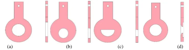
Figure 1Types of orifices, (a) concentric orifice, (b) eccentric orifice, (c) segmental orifice, (d) quadrant radius orifice.
Fig. 1 shows four types of orifices. Concentric orifice is the most famous among all of the orifice types which are available by Sadatomi et al. 2005. There are several numbers of advanced researches have been conducted for several decades. One of the main reasons for this to become the most famous is the inexpensiveness and the simplest design of it.
Quadrant radius orifice is used for the condition that fluids possessing high viscosity. The front side from the upstream side is shaped as a nozzle while the other side which opens towards the downstream is shaped as a sharp-edged orifice with an angle of 90 degree.
TABLE I shows the characteristics of the 4 types of orifices. We conclude that the most optimal orifice type for our research is the widely used Concentric Type Orifice The further research will be carried out with the Concentric type orifice.
TABLE ISPECIAL NOTES ON ORIFICE TYPES
Orifice Type Special Notes / Advantages / Disadvantages
Concentric Cheap, used with liquids, Used in liquid-gas multiphase flows
Eccentric Used mainly in liquid-solid Multiphase flows
Segmental Used with semi-liquids and higher concentration liquids
Quadrant Used with high viscosity liquids
B. Porous media
Porous media is used to generate the micro bubbles inside the pipe chamber, allowing the air which is filled inside the annular area to be sucked into the water with the pressure drop occurs due to the orifice plate or the solid sphere. To make the micro bubbles smaller, finer and also to generate a constant amount of micro bubbles we need to choose the most appropriate porous media available.
A vast number of porous types are available. Sometimes it is a bit of a complicated task to select one specific porous media out of several. So, in order to ease this task we use a set of results which are previously obtained by Yao et al. [8]. We conclude that the Stainless metal porous sheet is more efficient than the Polyolefin porous fiber which was used in this experiment. Finally, the stainless metal porous ring will be used in our micro bubble generator.
III.
SIMULATION MODEL AND THEORY
A. Simulation model
The trial design product was simulated to find out the optimum one. In this case we have to run eight different trial products.
First of all, we have to generate the geometry. In this case we will develop its 2D image which means a cross section of our trial design products. The 2D image will be generated in ANSYS design modeler platform. First, we generate the cross section view with adjoining straight lines, after that we resize the lines according to the trial design product parameters.
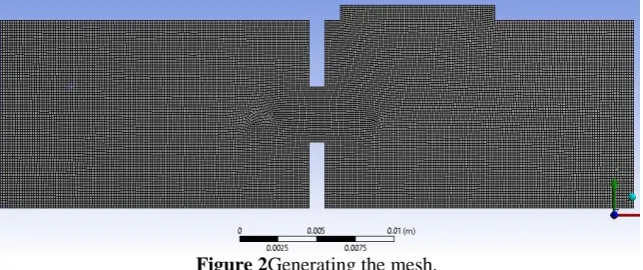
Figure 2Generating the mesh.
After finishing our work in ANSYS design modeler platform, we continue to generate the computational mesh of the object. We mark the boundaries of the trial design product. To improve the mesh to be more even and finer, we refine the meshed physical model by selecting the option refinement and setting up the refinement layers in to 3 layers. After this specific step we are able to get a very high-quality mesh which allows us to obtain more accurate simulation results. An illustration of the refined mesh is shown as Figure 2.
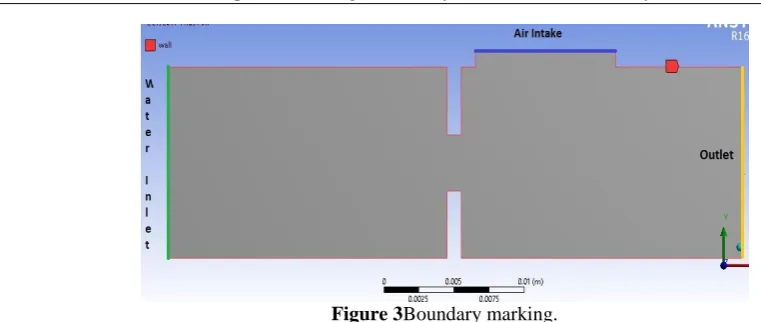
Figure 3Boundary marking.
In this 2D model we have four main boundaries which are shown in the above figure. They are Wall, Air Intake, Water Inlet and Outlet, respectively. We would like to point out an important thing in the boundary setting. In this diagram the fact that the Air Intake is assumed as the Wall boundary makes easier for us to obtain pressure graphs for the trial designs. Because if we can find out the pressure graphs for the air intake specifically, it eases our experimental work, because we only focus about the pressure loss on the air intake. Because larger the pressure loss we make on the porous surface, larger amount of air will be sucked into the water column.
The final step is to arrange the Fluent set up to run the simulation. In this step we will not deal with any kind of solution models because we are running a 2D model in single phase flow to obtain a pressure graph. So for the Materials we have to select Water Liquid (H20) from the ANSYS material database and add it to the set up. Next we have to consider about the boundary conditions. We have to set up the wall as "wall", water inlet as "velocity inlet", outlet as "pressure outlet" and air intake also as "wall” because we have to obtain the pressure graph for its surface. Then we carry out the Solution initialization with Hybrid initialization. Finally, we move to the Run Calculation. First, we set up the number of iterations as 1000, and start the calculation. These type of calculations takes a bit more time. A single calculation would take about two to three hours of time.
After the calculations, the final step is to obtain the pressure graphs which is the most important part of our simulation. For that we must click the "Plots" in the results bar and open a solution XY plot. Finally, you must finalize your X and Y coordinates and name them respectively. In this case the X coordinates will be the length of the micro bubble generator while the Y coordinates will be the pressure in Pascal. Then we need to select a surface to obtain the pressure distribution. As we mentioned earlier we want to find out the pressure loss of the air intake surface. So, we select the air intake as the surface and obtain the specific pressure graphs as shown in the above picture clearly.
B. Mathematic equations of the simulation
To get the flow properties such as the pressure distribution, velocity etc. in the microbubble generator, Navior-Stokes equations were employed and figured out in our simulation. Flow is assumed to be laminar, two dimensional and viscous. Specifically, the mathematic equations used in our study can be expressed as following:
Mass conservation equation:
i 0i
u
t x
. (1)
Momentum equation:
j
iji j
j i j
u p
u u
t x x x
, (2)
j
i k
ij
j j i k
u
u u
x x x x
2
3 . (3)
Energy conservation equation:
E
( E p )u k T h J u
Whereijis the Kronecker delta, 0 5 i2
p
E h . u
. hsand jsare the enthapy and mass fraction of species. keffis
effective coefficient of the thermal conductivity. To get the numerical solution of the abovementioned differential equations, they are all discretized by a Finite volume method and iteratively solved by SIMPLEC method.
IV.
RESULTS AND DISCUSSION
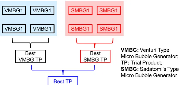
In this part, we present the results of the simulated pressure. As we said before there are two main trial design types to be tested. As shown in Figure 4, there are eight main pressure graphs for the eight different trial design specimens (Table II and Table III). So, we will compare these eight pressure graphs in two stages. Firstly, we will compare the first four Venturi type trial designs and find out which design allows the micro bubble generator to make the greatest pressure loss near the porous sheet. Then we will implement the same procedure forSadatomi's type micro bubble generator [9]. Thereafter we can obtain the best two trial designs out of Venturi type micro bubble generator and Sadatomi's type micro bubble generator, respectively.Finally, we will compare those two together and find out the best one from them.
Figure 4Procedure of obtaining the best performing trial product.
TABLE IIVENTURI TYPE MICRO BUBBLE GENERATOR TRIAL PRODUCTS
Product number Orifice diameter Air intake diameter Pipe diameter
VMBG1 3.5 mm 4.0 mm 12.0 mm
VMBG2 5.0 mm 4.0 mm 12.0 mm
VMBG3 6.5 mm 4.0 mm 15.0 mm
VMBG4 5.0 mm 4.0 mm 20.0 mm
TABLE IIISADATOMI TYPE MICRO BUBBLE GENERATOR TRIAL PRODUCTS
Product Number Sphere Diameter Air Intake Diameter Pipe Diameter
SMBG1 9.53mm 0.5mm 13.0mm
SMBG2 9.53mm 0.5mm 12.0mm
SMBG3 9.53mm 0.5mm 11.0mm
SMBG4 12.7mm 0.5mm 14.7mm
(a) (b)
Figure 5(a)Comparison of Venturi type trial product pressure graphs, (b) comparison of Sadatomi's type trial product pressure graphs.
Figure 6 shows the pressure comparison of the four Sadatomi’s type trial design products. The four trial products have 12.7 mm and 9.53mm diameter of solid spheres with different size of pipe chamber size such as 11 mm,12 mm ,13mm and 14.7 mm. In this graph you can clearly identify the performance of each and every trial design product and it clearly shows that the trial design product with the 12.7 millimeters of sphere diameter creates the greatest pressure loss out of all the four trial design products. So, we confirm that the trial design product named "SMBG4" with specifications of 12.7mm sphere diameter and 14.7mm of chamber diameter has shown the best performance out of Sadatomi type trial products in the ANSYS simulations.
Finally, we have obtained the two best performing trial design products from both Venturi type and Sadatomi type. The trial product names are VMBG1 and SMBG4 respectively. For the final comparison we will compare these two trial design products in a same platform to find out which is the best performing trial design product out of these two selected design specimens in both types of micro bubble generators.
Figure 6Comparison of the two best performing trial products.
Finally, after several number of simulations, we state that the best performing and also the best optimal design dimensions are given by the "VMBG1" trial product. We will use the exact same dimensions of "VMBG1" for the final design of the micro bubble generator.
V.
FINALDESIGNOFTHEMICROBUBBLE GENERATOR
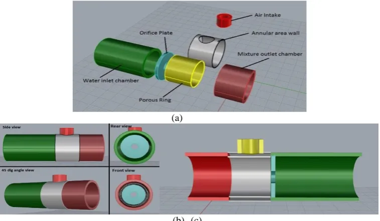
After completing the main five tasks of the project, we bring every result which obtained in those steps in to a one single creation. After carefully verifying the data, conclusions and the design dimensions the 3D design was built in Rhino design software (Figure 8).
The green color chamber is the water intake, where the pressurized water is introduced to the micro bubble generator. The light blue color part is the concentric type orifice plate which will be used to create the pressure loss inside the chamber. The yellow color part is the air intake. Grey color ring shape represents the porous media while the red color chamber is the exit of the two-phase flow.
(a)
(b) (c)
Figure 7 Final design of the micro bubble generator, (a) assembly design of the micro bubble generator final design, (b) 3D of the micro bubble generator, (c)cross-section of the micro bubble generator.
VI.
CONCLUSION
This paper gives a brief introduction of the micro bubble generators and its mechanism of multiphase flow theory. After identifying the disadvantages of the protein skimmer, we gradually developed and designed a micro bubble generator to overcome the disadvantages. From the selection of the optimal micro bubble generator type to the gain of the optimal design dimensions, simulations are carefully handled and demonstrated in this paper. After separating the project in to five tasks, each task was handled step by step. Also the step by step demonstration of ANSYS simulation results is very helpful for understanding this paper. Through the simulation and result analysis, we found out that "VMBG1" trial design product has the best optimal dimensions for the micro bubble generator. The final design of the micro bubble generator was done according to the optimized dimensions. The final engineering drawing is shown at the end of this project. We believe that we can achieve the predicted results out of this new micro bubble generator when it is replaced with the needle wheel impeller of the protein skimmer.
ACKNOWLEDGEMENT
This work is supported by the National Natural Science Foundation of China (NSFC) (Grant No. 51706098), Natural Science Foundation of Jiangsu Province (No. BK20170792).
REFERENCES
[1]. Rahman, M.M., Kadowaki, S., Linn, S.M. and Yamada, Y. 2004. Effects of Protein Skimming on Water Quality, Bacterial
Abundance and Abalone Growth in Land Based Recirculating Aquaculture Systems, Journal of Fisheries & Aquatic Science, 7(2): 150-161. doi: 10.3923/jfas.2012.150.161.
[2]. Ikeura, H., Kobayashi, F. and Tamaki, M. 2011. Removal of residual pesticide, fenitrothion, in vegetables by using ozone
microbubbles generated by different methods, Journal of Food Engineering, 103(3): 345-349. doi: 10.1016/j.jfoodeng.2010.11.002.
[4]. Terasaka, K., Ai, H. and Nishino, T. 2011. Development of microbubble aerator for waste water treatment using aerobic activated sludge, Chemical Engineering Science, 66(14): 3172-3179. doi: https://doi.org/10.1016/j.ces.2011.02.043.
[5]. Sadatomi, M., Kawahara, A., Matsuyama, F. and Kimura, T. 2007. An advanced microbubble generator and its application to a
newly developed bubble-jet-type air-lift pump, Multiphase Science & Technology, 19(4): 323-342. doi: 10.1115/FEDSM2003-45162.
[6]. Yao, J., Tanaka, K., Kawahara, A. and Sadatomi, M. 2013. Performance Evaluation of an Air Assisted Atomizer with Liquid
Siphon, Journal of Applied Sciences, 13(22): 4985-4993. doi: 10.3923/jas.2013.4985.4993.
[7]. Yao, J., Tanaka, K., Kawahara, A. and Sadatomi, M. 2014. Geometrical Effects on Spray Performance of a Special Twin-fluid
Atomizer without Water Power and its CO2 Absorption Capacity, Japanese Journal of Multiphase Flow, 27(5): 511-520. doi:
10.3811/jjmf.27.511.
[8]. Yao, J., Furusawa, S., Kawahara, A. and Sadatomi, M. 2014a. Influence of some geometrical parameters on the characteristics of
prefilming twin-fluid atomization, Transactions- Canadian Society for Mechanical Engineering, 38(3): 391-404.
[9]. Sadatomi, M., Kawahara, A., Kano, K. and Ohtomo, A. 2005. Performance of a new micro-bubble generator with a spherical body
in a flowing water tube, Experimental Thermal & Fluid Science, 29(5): 615-623. doi: 10.1016/j.expthermflusci.2004.08.006.