Performance Analysis of VM Scheduling Algorithm
of CloudSim in Cloud Computing
1
Md. Ashifuddin Mondal,
2Sayan Choudhury,
3Md.Sohel Islam
1Assistant Professor, Dept. of CSE, Narula Institute of Technology, Agarpara, Kolkata, WB, India
2,3B.Tech Student, Dept. of CSE, Narula Institute of Technology, Agarpara, Kolkata, WB, India
Abstract
Cloud Computing is the emerging technology in IT industry which is built on the basis of sharing of resources over a network. To
maximize benefits of cloud computing, developers must design
mechanisms that optimize the use of architectural and deployment
models. The users of cloud are growing day by day, as a result
the number of users is increasing and hence it is becoming a serious issue for the developers to schedule the components. Scheduling refers to a set of policies to control the order of work to be performed by a computer system. Due to the complexity
and scale of shared resources, it is often hard to analyze the
performance of new scheduling and provisioning algorithms on
actual Cloud test beds. Therefore, simulation tools are becoming
very useful for the evaluation of the Cloud computing model which
allows researchers to rapidly evaluate the efficiency, performance
and reliability of their new algorithms on a large heterogeneous
Cloud infrastructure. For simulation we need a simulation tool,
we are using CloudSim. In this paper we will be analyzing the existing Host allocation policy and VM allocation policy in terms of average waiting time and throughput of CloudSim.
Keywords
Load Balancing, CloudSim, Cloudlet, Data Centre, Broker, Scheduling Policy, VM.
I. Introduction
Cloud computing is a distributed computing model that provides
users with virtualized, scalable software and hardware services over the internet, in a pay-as-you-go way. These services are provided according to several fundamental models like IaaS, PaaS, and SaaS. The bottom layer is Infrastructure as a Service (IaaS). It has a service-oriented architecture. It provides access to virtualized computer hardware resources, including machines, network resources, and storage. The most famous service provider
is Amazon EC2/S3.The middle layer is Platform as a Service
(PaaS), a service platform that developers can use to deploy their
own applications. It Provides network access to a programming or
runtime environment with data structures embedded in it.
Well-known PaaS service providers include Amazon Web Services and Google App Engine. The top layer is Software as a Service
(SaaS), which enables each user to access services according to
his or her requirements.
It provides network accessible access to software application programs. Examples of SaaS service providers are Microsoft’s
online update service, Trend Micro Internet Security and so on.
The importance of these services are given in the recent report
from Berkeley as: “Cloud Computing, the long-held dream of
computing as a utility has the potential to transform a large part
of the IT industry, making software even more attractive as a service” [3, 7-6].
Many researchers have been caring out works on the scheduling and allocation of the resources in the cloud and they have found that scheduling is a critical problem in Cloud computing. So scheduling is the leading issue in establishing Cloud computing
systems. The main goal of these scheduling algorithms is to minimize the execution time and cost to achieve the maximum resource utilization. The rest of the sections are organized as follows. Section II contains Load Balancing. Section III presents Simulation in cloud computing: CloudSim. Section IV contains scheduling architecture and presents two scheduling policies and its comparison. Section V provides effect of different scheduling policies on task execution. Section VI provides the results. Section VII concludes the paper with a summary of our future works.
II. Load Balancing
Load balancing technique is a process in which no node of a system remains in idle state while other nodes are over utilized. It plays a big role behind the success of the system. Load balancing can work in two ways – Co – operative way and non Co – operative way. In co – operative way the nodes work simultaneously in order to optimize the overall response time. In non co – operative way the nodes run independently in order to improve the response time of local tasks.
Load balancing algorithm can be divided into two categories – Static load balancing algorithm and Dynamic load balancing algorithm. A static load balancing algorithm does not take into account the previous state or behavior of a node while distributing the load while dynamic load balancing algorithm checks the previous state of node while distributing the load. Dynamic load balancing is advantageous over static load balancing because if any node fails it will not freeze the entire system. Important
objectives of load balancing algorithm are cost effectiveness, flexibility and prioritizing resources. Round Robin and First Come
First Serve scheduling algorithm falls under static load balancing algorithm.
III. Simulation In Cloud Computing CloudSim
CloudSim is a framework which allows modeling, simulation
and experimenting on designing Cloud computing infrastructure.
CloudSim toolkit is developed in the GRIDS laboratory at the
University of Melbourne. CloudSim facilitates switching between space shared and time shared allocation of cores to virtualized services. There are many classes which are the building blocks
of the CloudSim simulator [4]. Few of the main classes are
BWProvisioner: This abstract class models the provisioning policy of bandwidth to VMs that are deployed on a Host component. The function of this component is to undertake the allocation of network bandwidths to set of competing VMs deployed across the data centre. Cloud system developers and researchers can
extend this class with their own policies (priority, QoS) to reflect the needs of their applications [1].
1. Cloudlet
This class models the Cloud-based application services (content delivery, social networking, business workflow), which are
commonly deployed in the data centers. CloudSim represents the complexity of an application in terms of its computational
instruction length and amount of data transfer that needs to be
undertaken for successfully hosting the application [2].
2. Data Centre
This class models the core infrastructure level services (hardware, software) offered by service provider (Amazon, Azure, App
Engine) in a Cloud computing environment. It encapsulates a set of compute hosts that can be either homogeneous or heterogeneous
as regards to their resource configurations (memory, cores, capacity, and storage).Furthermore, every DataCenter component
instantiates a generalized application provisioning component that
implements a set of policies for allocating bandwidth, memory, and storage devices [2].
3. Data Center Broker
This class models a broker, which is responsible for mediating between users and service providers depending on users’ QoS
requirements and deploys service tasks across Clouds. The broker
acting on behalf of users. It identifies suitable Cloud service
providers through the Cloud Information Service (CIS) and negotiates with them for an allocation of resources that meets
QoS needs of users. The researchers and system developers must
extend this class for conducting experiments with their custom
developed application placement policies [3].
4. Datacenter Characteristics
This class extends GridSim’sResourceCharacteristics by adding
description of cost to use datacenter resources.
5. Datacenter Tags
This class contains tags to be used along with the messages, to
identify different message types.
6. Host
This class models a physical service in a Cloud-based Data Center. It contains an amount of memory and storage, a list of processing elements (to represent a multi-core machine), an allocation policy for sharing the processing power among virtual machines, and
policies to provisioning memory and bandwidth to the virtual machines.
7. Virtual Machine
This class models an instance of a VM, whose management during
its life cycle is the responsibility of the Host component. Every VM component has access to a component that stores the characteristics
related to a VM, such as memory, processor, storage, and the VM’s internal provisioning policy, which is extended from the abstract component called VMScheduling [4].
8. Virtual Machine List
A helper class to store a bunch of virtual machines. It is passed to the DatacenterBroker as the description of virtual machines to be instantiated for deployment in the Cloud.
9. VM Characteristics
This class contains the description of the virtual machine: memory
required, bandwidth, number of CPUs, and provisioning policy in use. Different virtual machine templates, like the instances offered by Amazon, are modelled in this class, with the use of the related parameters for each of VM fields, like memory, operating system, and number of cores [4].
10. VMMAl Location Policy
This is an abstract class implemented by a Host component that
models the policies (space-shared, time-shared) required for
allocating processing power to VMs. The functionalities of this
class can easily be overridden to accommodate application specific processor sharing policies [4].
11. VMScheduler
This abstract class is extended by implementations of policies to share processing power among Cloudlets running in a virtual
machine. As described previously, two policies are offered: space-shared (SpaceSharedVMScheduler) and time-shared (TimeSharedVMScheduler) [3].
IV. Scheduling Architecture
The objective of scheduling is to maximize the resource utilization and minimize processing time of the tasks. The scheduler should order the tasks in a way such that quality of service is improves and
efficiency of the tasks are maintained. An efficient task scheduling
algorithm must yield less response time and must allow more no. of tasks to be submitted by the user.
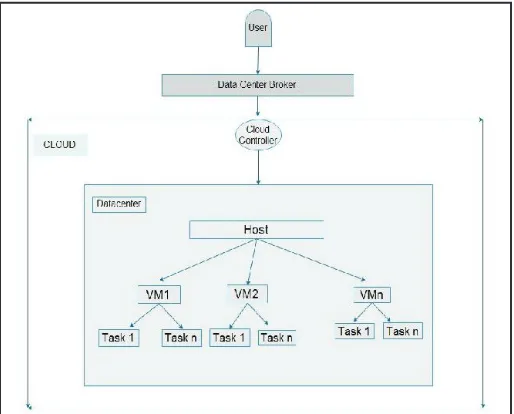
In scheduling architecture user submits the task to the datacentre
broker, this broker helps in scheduling the task on virtual machine. In datacentre there are no. of hosts, on which no. of virtual machines
are scheduled and on them VM tasks are scheduled according to the scheduling policy taken by datacentre broker.
Fig. 1: Scheduling Architecture
V. VM Scheduling Policy
VM scheduling policy is implemented in two levels in CloudSim
namely Host level and VM level. At the host level, it is possible to
specify how much of the overall processing power of each core in
a host will be assigned to each VM. At the VM level, the Virtual Machines assign specific amount of the available processing power
to the individual task units that are hosted within its execution engine. In Host level allocation the available VM’s are allotted to the free PE (CPU) or hosts and in VM level allocation the available cloudlets are allotted to the free VM’s. There are two types of policies based on which scheduling is done in CloudSim – Space Shared scheduling policy and Time Shared scheduling policy. In Space Shared scheduling policy for Host level one VM is
assigned at a time to a CPU core, when this VM finishes its task
to a virtual machine, when this task is completed it schedules
another task to the virtual machine. This policy behaves same
as the First Come First Serve (FCFS) scheduling algorithm [5], [2], [9], [10].
Algorithm of Space Shared Policy: Step 1: Tasks are arranged in a queue.
Step 2: First task is scheduled on the given virtual machine.
Step 3: When first task is completed it assigns the next task from
the queue.
Step 4: If queue is empty it checks for new tasks. Step 5: Then repeat Step 1.
Step 6: End.
Same algorithm is applicable for both Host level and VM level scheduling.
In Time Shared scheduling policy for Host level all virtual
machines are scheduled on the CPU cores at the same time, it
schedules the time among all virtual machines. In Time Shared scheduling policy for VM level all tasks are scheduled on the
virtual machine at the same time, it schedules the time among all tasks. This policy behaves same as the Round Robin (RR) scheduling algorithm [5], [2], [9], [10].
Algorithm of Time Shared Policy:
Step 1: All the tasks are arranged in a queue.
Step 2: Then schedule the tasks simultaneously on the virtual machine.
Step 3: When queue is empty it checks for new tasks. Step 4: If new task arrives it schedules similarly as in Step 2. Step 5: End.
Same algorithm is applicable for both Host level and VM level scheduling.
VI. Effect of Different Scheduling Policies on Task Execution
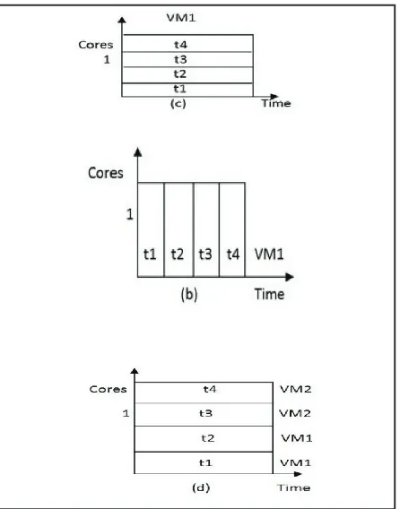
Fig. 2: Effects of different Scheduling Policies on task execution
:(a) Time Shared for VMs and Space Shared for tasks. (b) Space Shared for VMs and Space Shared for tasks. (c) Space Shared for VMs and Time Shared for tasks. (d) Time Shared for VMs and Time Shared for tasks
Here we consider one datacenter with one host with 1 CPU core receiving request for hosting two VM’s and running four tasks
units, namely t1, t2, t3, t4. We did not specify which task will run in which VM, this decision is taken by the scheduling policy. In fig. 2(a), a time-shared scheduling is used for VMs, and a space-shared one is used for task units. In this case, each VM receives a time slice of each processing core, and then slices are distributed to task units on space-shared basis. As the core is shared, the amount
of processing power available to the VM is comparatively lesser
than the other scenarios. As task unit assignment is space-shared, hence only one task can be allocated to each core, while others
are queued in for future consideration.
In fig. 2(b), a space-shared policy is used for both VMs and task units, as each VM contains two cores, only one VM can run at a given occasion of time. Therefore, VM2 can only be assigned to the core if VM1 finishes the execution of task units. The same
happens for tasks hosted within the VM: as each task unit demands only one core. But here VM1 takes all the tasks since the tasks are also scheduled via space shared policy.
In fig. 2(c), a space shared policy is used for allocating VMs, but a time-shared policy is used for allocating individual task units within VM. Hence, during a VM lifetime, all the tasks assigned to it
dynamically context switch until their completion. This allocation
policy enables the task units to be scheduled at an earlier time, but significantly affecting the completion time of task units that are
ahead the queue. In this case as well only VM1 gets the chance to
execute all the tasks since it is scheduled via space shared policy,
as a result VM2 does not get a chance to run.
In fig. 2(d), a time-shared allocation is applied for both VMs and task units. Hence, the processing power is concurrently shared
by the VMs and the shares of each VM are concurrently divided
among the task units assigned to each VM. In this case, there are
no queues either for virtual machines or for task units.
VII. Simulation Result
A. Experimental Scenario
In this section, we examine the results of Space Shared and Time
Shared approach for both Host level and VM level allocation policy in terms of average waiting time and throughput. CloudSim implements both Time Shared and Space Shared scheduling policy.
The Host configuration is shown in Table 1.
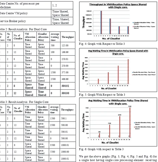
Table 1: Host Configuration Table
Parameter Values VM Image size 10000
VM Memory 512 MB VM Bandwidth 1000
Data Centre Architecture X86
Data centre OS Linux Data Centre VMM Xen Data Centre No. of Machines 1 Data Centre Memory per Machines 2048 MB
Data Centre storage per Machine 10,000 MB
Data Centre No. of processor per
Machines 1, 2
Data Centre VM policy Time Shared, Space Shared
Service Broker policy Time, Shared, Space Shared
Table 2: Result Analysis: For Dual Core
No. of Core
No. of VM
No. of Cloudlet
VM Allocation Policy
Cloudlet Allocation Policy
Average waiting
time Throughput
2 2 8 Time Shared Space Shared 500 125.00
2 2 12 Time Shared Space Shared 100 166.66
2 2 8 Time Shared Time Shared 0 250.01
2 2 12 Time Shared Time Shared 0 250.00
2 2 8 Space Shared Space Shared 1500 375.00 2 2 12 Space
Shared Space Shared 2500 466.66
2 2 8 Space Shared Time Shared 0 500.01
2 2 12 Space Shared Time Shared 0 500.00
Table 3: Result Analysis: For Single Core No.
of Core
No. of VM
No. of Cloudlet
VM Allocation Policy
Cloudlet Allocation Policy
Average waiting
time Throughput
1 2 8 Time Shared Space Shared 1500 500.1
1 2 12 Time Shared Space Shared 2500 500.00
1 2 8 Time Shared Time Shared 0 500.01
1 2 12 Time Shared Time Shared 0 500.00
1 2 8 Space Shared Space Shared 3500 1000.01
1 2 12 Space Shared Space Shared 5500 1000.00
1 2 8 Space Shared Time Shared 0 1000.01
1 2 12 Space Shared Time Shared 0 1000.00
Fig. 3: Graph With Respect to Table 3
Fig. 4: Graph with Respect to Table 3
Fig. 5: Graph With Respect to Table 3
Fig. 6: Graph with respect to Table 3
We got the above graphs (Fig. 3, Fig. 4, Fig. 5 and Fig. 6) for
a single host having single core processing element receiving request for hosting two VM’s and running several cloudlet’s. We
did not specify which cloudlet will run in which VM, this decision
is taken by the scheduling policy.
The Fig. 5 represents average waiting time of cloudlet when VMAllocation policy is space shared and cloudlet allocation
policy are space shared and time shared. As host is single core,
at a time only one VM will execute. Hence single VM execute all the cloudlets either time shared or space shared basis. So here second VM will not get a chance to run. For time shared cloudlet allocation policy average waiting time is zero. But for space shared cloudlet allocation policy there is some waiting time as it works as a FCFS basis.
The Fig. 6 represents average waiting time of cloudlet when
The Fig. 3 represents throughput of cloudlet when VMAllocation policy is space shared and cloudlet allocation policy are space shared and time shared. Hence only one VM will run in the host
and other VM will not get a chance as the first allocated VM
execute all the cloudlet.
The Fig. 4 represents throughput of cloudlet when VMAllocation policy is time shared and cloudlet allocation policy are space shared and time shared. So two VM will run concurrently.
VIII. Conclusion and Future Work
This paper analyzes that space shared scheduling policy for VM
shows better results as compared to Time-shared scheduling
policy in terms of throughput in case of single core when cloudlet size is small. But Avg. waiting time is low for time shared VM
allocation. This can be verified from the fact that the throughput
in space shared allocation policy is more than the throughput of time shared allocation policy both in case of single core and dual
core. In time shared cloudlet allocation policy, the Avg. waiting time for cloudlet is zero. In further we will try to device efficient
VM scheduling policy for better results in terms of waiting time and throughput of cloudlet.
References
[1] Rodrigo N. Calheiros, Rajiv Ranjan, César A. F. De Rose, RajkumarBuyya,“CloudSim: A Novel Framework for
Modeling and Simulation of Cloud Computing Infrastructures and Services”.
[2] Raj Kumar Buyya, Rajiv Ranjan, Rodrigo N. Calheiros,
"Modeling and Simulation of Scalable Cloud Computing Environments and the CloudSim Toolkit: Challenges and Opportunities”.
[3] Rodrigo N. Calheiros, Rajiv Ranjan, Anton Beloglazov, C´esar A. F. De Roseand Raj Kumar Buyya,"CloudSim: A toolkit for
modeling and simulation of cloud computing environments
and evaluation of resourceprovisioning algorithms”, SOFTWARE –PRACTICE AND EXPERIENCESoftw. Pract.Exper.2011; 41: 23–50, 2010. In Wiley Online Library
(wileyonlinelibrary.com).
[4] Rodrigo N. Calheiros, Rajiv Ranjan, Anton Beloglazov, César A. F. De Rose, RajkumarBuyya,"CloudSim: A Toolkit for the Modeling and Simulation of Cloud ResourceManagement and Application Provisioning Techniques”, Software: Practice and Experience, 41(1), pp. 23-50, Wiley, January 2011.
[5] Himani, Harmanbir Singh Sidhu,"Comparative Analysis of Scheduling Algorithms of Cloudsim in Cloud Computing”, International Journal of Computer Applications, Vol. 97, No. 16, July 2014.
[6] Soumya Ray, Ajanta De Sarkar,“Execution Analysis of Load Balancing Algorithms In Cloud Computing Environment”, International Journal on Cloud Computing: Services and Architecture (IJCCSA),Vol. 2, No. 5, October 2012. [7] M. Armbrust, A. Fox, R. Griffith, A. Joseph, R. Katz, A.
Konwinski, G. Lee, D. Patterson, A. Rabkin, I. Stoica, M.
Zaharia. “Above the Clouds: A Berkeley View of Cloud
computing”, Technical Report No. UCB/EECS-2009-28, University of California at Berkley, USA, Feb. 10, 2009. [8] R. Ranjan, R. Buyya,“Decentralized Overlay for Federation
of Enterprise Clouds. Handbook of Research on Scalable Computing Technologies”, K. Li et. al. (ed), IGI Global, USA, 2009.
[9] IsamAzawiMohialdeen,“A Comparative Study of Scheduling Algorithms in Cloud Computing Environment”, 2013 Science
Publications.