University of Pennsylvania
ScholarlyCommons
Publicly Accessible Penn Dissertations
1-1-2013
Approaches to Mitigate Metal Catalyst
Deactivation in Solid Oxide Fuel Cell (SofC) Fuel
Electrodes
Lawrence Adijanto
University of Pennsylvania, [email protected]
Follow this and additional works at:http://repository.upenn.edu/edissertations
Part of theChemical Engineering Commons,Nanoscience and Nanotechnology Commons, and theOil, Gas, and Energy Commons
This paper is posted at ScholarlyCommons.http://repository.upenn.edu/edissertations/728 For more information, please [email protected].
Recommended Citation
Adijanto, Lawrence, "Approaches to Mitigate Metal Catalyst Deactivation in Solid Oxide Fuel Cell (SofC) Fuel Electrodes" (2013).
Publicly Accessible Penn Dissertations. 728.
Approaches to Mitigate Metal Catalyst Deactivation in Solid Oxide Fuel
Cell (SofC) Fuel Electrodes
Abstract
While Ni/YSZ cermets have been used successfully in SOFCs, they also have several limitations, thus motivating the use of highly conductive ceramics to replace the Ni components in SOFC anodes. Ceramic electrodes are promising for use in SOFC anodes because they are expected to be less susceptible to sintering and coking, be redox stable, and be more tolerant of impurities like sulfur. In this thesis, for catalytic studies, the infiltration procedure has been used to form composites which have greatly simplified the search for the best ceramics for anode applications.
In the development of ceramic fuel electrodes for SOFC, high performance can only be achieved when a transition metal catalyst is added. Because of the high operating temperatures, deactivation of the metal catalyst by sintering and/or coking is a severe problem. In this thesis, two approaches aimed at mitigating metal catalyst deactivation which was achieved by: 1) designing a catalyst that is resistant to coking and sintering and 2) developing a new method for catalyst deposition, will be presented.
The first approach involved synthesizing a self-regenerating, "smart" catalyst, in which Co, Cu, or Ni were inserted into the B-site of a perovskite oxide under oxidizing conditions and then brought back to the surface under reducing conditions. This restores lost surface area of sintered metal particles through an oxidation/ reduction cycle. Results will be shown for each of the metals, as well as for Cu-Co mixed metal systems, which are found to exhibit good tolerance to carbon deposition and interesting catalytic properties.
The second strategy involves depositing novel Pd@CeO2 core-shell nanostructure catalysts onto a substrate surface which had been chemically modified to anchor the nanoparticles. The catalyst deposited onto the chemically modified, hydrophobic surface is shown to be uniform and well dispersed, and exhibit excellent thermal stability to temperatures as high as 1373 K. Similar metal catalyst deposition method was also employed to access their suitability for use in SOFC anodes.
Degree Type
Dissertation
Degree Name
Doctor of Philosophy (PhD)
Graduate Group
Chemical and Biomolecular Engineering
First Advisor
Raymond J. Gorte
Second Advisor
John M. Vohs
Keywords
catalyst, ceramic anode, core-shell nanostructures, intelligent catalyst, solid oxide fuel cells, vanadates
Subject Categories
Chemical Engineering | Nanoscience and Nanotechnology | Oil, Gas, and Energy
APPROACHES TO MITIGATE METAL CATALYST DEACTIVATION IN
SOLID OXIDE FUEL CELL (SOFC) FUEL ELECTRODES
Lawrence Adijanto
A DISSERTATION
in
Chemical and Biomolecular Engineering
Presented to the Faculties of the University of Pennsylvania
in Partial Fulfillment of the Requirements for the
Degree of Doctor of Philosophy
2013
Supervisor of Dissertation Co-Supervisor of Dissertation
___________________________ ____________________________
Raymond J. Gorte, Professor, CBE John M. Vohs, Professor,CBE
Graduate Group Chairperson
____________________________
Raymond J. Gorte, Professor, Chemical and Biomolecular Engineering
Dissertation Committee
Warren D. Seider, Professor, Chemical and Biomolecular Engineering
ii This work is dedicated to my Family
iii
Acknowledgements
First and foremost, I would like to express my sincere appreciation to my thesis
advisors, Professor Ray Gorte and Professor John Vohs, for their unconditional support,
guidance, patience, and encouragement throughout my research work. I would also like
to thank all the students that I have worked with during the past four years, particularly,
Venu Balaji Padmanabhan. Moreover, I want to give thanks to my committee, Professor
Warren Seider and Professor Paulo Arratia for their support and guidance.
My appreciation likewise extends to my colleagues and friends as they are the
sources of laughter, joy, and support. My life at Penn would not have been the same
without them. I particularly wish to offer my special thanks to:
Dr. Rainer Küngas, who has been an inspiring, supportive, and patient role model to
me, for always entertaining even my trivial questions.
Dr. Matteo Cargnello for always being there for discussion, tennis and meals at Han
Dynasty.
Lu Yao and Kwadwo Tettey for your time and support during my job search.
Ami Tiyaboonchai for always providing great support in all my struggles and
frustrations in my life and studies.
In addition, I wish to thank the financial support for this project, which was
provided by the Office of Naval Research (N00014-11-1-0229), and the U.S. Department
of Energy, Office of Basic Energy Sciences (DE-FG02-13ER16380).
Finally, my deepest gratitude goes to my family for their love and support
iv ABSTRACT
APPROACHES TO MITIGATE METAL CATALYST DEACTIVATION IN SOLID
OXIDE FUEL CELL (SOFC) FUEL ELECTRODES
Lawrence Adijanto
Raymond J. Gorte
John M. Vohs
While Ni/YSZ cermets have been used successfully in SOFCs, they also have
several limitations, thus motivating the use of highly conductive ceramics to replace the
Ni components in SOFC anodes. Ceramic electrodes are promising for use in SOFC
anodes because they are expected to be less susceptible to sintering and coking, be redox
stable, and be more tolerant of impurities like sulfur. In this thesis, for catalytic studies,
the infiltration procedure has been used to form composites which have greatly simplified
the search for the best ceramics for anode applications.
In the development of ceramic fuel electrodes for SOFC, high performance can
only be achieved when a transition metal catalyst is added. Because of the high operating
temperatures, deactivation of the metal catalyst by sintering and/or coking is a severe
v which was achieved by: 1) designing a catalyst that is resistant to coking and sintering
and 2) developing a new method for catalyst deposition, will be presented.
The first approach involved synthesizing a self-regenerating, “smart” catalyst, in
which Co, Cu, or Ni were inserted into the B-site of a perovskite oxide under oxidizing
conditions and then brought back to the surface under reducing conditions. This restores
lost surface area of sintered metal particles through an oxidation/reduction cycle. Results
will be shown for each of the metals, as well as for Cu-Co mixed metal systems, which
are found to exhibit good tolerance to carbon deposition and interesting catalytic
properties.
The second strategy involves depositing novel Pd@CeO2 core-shell nanostructure
catalysts onto a substrate surface which had been chemically modified to anchor the
nanoparticles. The catalyst deposited onto the chemically modified, hydrophobic surface
is shown to be uniform and well dispersed, and exhibit excellent thermal stability to
temperatures as high as 1373 K. Similar metal catalyst deposition method was also
vi
Table of Contents
Chapter 1. Introduction 1
1.1 Motivation 1
1.2 Solid Oxide Fuel Cells (SOFCs) 2
1.2.1 SOFC Operating Principles 2
1.2.2 Three-Phase Boundary (TPB) 5
1.3 Materials for SOFC 5
1.3.1 Perovskite Materials 6
1.3.2 Cathode (air electrode) 7
1.3.3 Electrolyte 9
1.3.4 Interconnect 10
1.3.5 Anode (fuel electrode) 11
1.4 Ceramic Electrodes as Alternative Anode Materials 12
1.5 Approaches to Mitigate Metal Catalyst Deactivation 13
1.6 References 15
Chapter 2. Experimental Techniques 26
2.1 Materials Synthesis 26
2.1.1 Mixed Oxides 26
2.1.2 Pd@CeO2 Core-Shell Nanostructures 26
2.2 Fuel Cell Preparation 27
2.2.1 Tape Casting 28
vii
2.2.3 Cathode Preparation 30
2.2.4 Anode Preparation 31
2.2.5 Preparation for Testing 31
2.2.6 Advantages of the Infiltration Method over Traditional Method
31
2.3 Cell Performance Measurements 33
2.3.1 V-i Polarization Curves 33
2.3.2 Electrochemical Impedance Spectroscopy 34
2.4 Composite Slabs 36
2.5 Surface Chemical Modification of Metal Oxide Powders or Planar Supports
36
2.5.1 Liquid Silanization 36
2.5.2 Gas Silanization 37
2.5.3 Liquid Phosphonation 37
2.6 Materials Characterization Techniques 38
2.6.1 Electrical Conductivity Measurements (4 Point DC-Probe) 38
2.6.2 X-Ray Diffraction (XRD) 38
2.6.3 Scanning Electron Microscopy (SEM) 39
2.6.4 BET Surface Area Measurements 39
2.6.5 Atomic Force Microscopy (AFM) 39
2.6.6 Coulometric Titration 40
2.7 References 43
Chapter 3. SOFC Anodes Based on Infiltration of Tungsten Bronzes 48
viii
3.2 Experimental 51
3.3 Results 54
3.4 Discussion 71
3.5 Conclusion 73
3.6 References 74
Chapter 4. Physical and Electrochemical Properties of Alkaline Earth Doped, Rare Earth Vanadates
81
4.1 Introduction 82
4.2 Experimental 83
4.3 Results and Discussion 86
4.4 Conclusion 102
4.5 References 103
Chapter 5. Transition Metal-Doped Rare Earth Vanadates: A Regenerable Catalytic Material for SOFC Anodes
108
5.1 Introduction 109
5.2 Experimental 111
5.3 Results and Discussion 113
5.4 Summary and Conclusion 129
5.5 References 132
Chapter 6. Polarization-Induced Hysteresis in (CuCo)-Doped Rare Earth Vanadates SOFC Anodes
139
6.1 Introduction 140
6.2 Experimental 141
ix
6.4 Conclusion 156
6.5 References 158
Chapter 7. Exceptional Thermal Stability of Pd@CeO2 Core-Shell Catalyst
Nanostructures Grafted onto an Oxide Surface
163
7.1 Introduction 164
7.2 Experimental 164
7.3 Results and Discussion 167
7.4 Conclusion 182
7.5 References 183
Chapter 8. Synthesis and Stability of Monolayer Films of Pd@CeO2
Core-Shell Catalysts for Solid Oxide Fuel Cell Anodes
187
8.1 Introduction 188
8.2 Experimental 189
8.3 Results and Discussion 192
8.4 Conclusion 212
8.5 References 214
Chapter 9. Stability and Performance of Infiltrated La0.8Sr0.2CoxFe1-xO3
Electrodes with and without Sm0.2Ce0.8O1.9 Interlayers
216
9.1 Introduction 217
9.2 Experimental 220
9.3 Results and Discussion 222
9.4 Conclusion 234
9.5 References 235
x
List of Tables
Table 1.1 Perovskite materials used for different cell components. 7
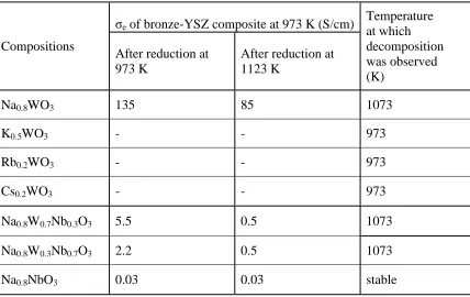
Table 3.1 Summary of the electronic conductivities of the bronze-YSZ
composites used in this study reduced in H2 (3% H2O). 66
Table 4.1 AE solubility limit in various REAEVO4 materials. 89
Table 4.2 Specific surface areas of Ce0.7Sr0.3VO3.85-YSZ composites fabricated
at 973 K, before and after reduction. 97
Table 5.1 Transition metal solubility limit in Ce1-xTMxVO4-0.5x. 115
Table 5.2 BET surface areas of Ce0.8Ni0.2VO3.90-YSZ composites. 119
Table 5.3 The percentage weight changes measured after reducing the samples in humidified H2 at 973 K for 2 h before exposing them to dry
methane at 973 K for 3 h. 121
Table 5.4 Maximum power density and anode ASR. 124
Table 6.1 Percentage weight changes after exposure to dry CH4 at 1073 K for
3 h. 147
Table 7.1 Ellipsometry thickness and water contact angle measurements. 174
Table 8.1 Electrochemical performance of cells with various anode compositions. The anodes were fabricated by impregnation. All the fuel cells are 45 wt. % La0.8Sr0.2Cr0.5Mn0.05O3-YSZ composite anodes. The anode ASR can be obtained by subtracting from the total resistance the ohmic (0.3 Ω cm2) and cathode (0.2 Ω cm2
)
xi
List of Figures
Figure 1.1 The operating principle of a solid oxide fuel cell. 4
Figure 2.1 Cell fabrication by tape-casting and infiltration. 28
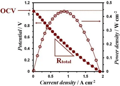
Figure 2.2 An example V-i polarization curve of an SOFC. 34
Figure 2.3 An example electrochemical impedance spectra from an SOFC. 35
Figure 2.4 Schematic of Coulometric Titration apparatus. 41
Figure 3.1 Colors of NaxWO3 at different x values. 50
Figure 3.2 XRD patterns of Na0.8WO3-δ synthesized in humidified (3% H2O) H2 at following temperatures: a) 823 K b) 973 K c) 1023 K d) 1073 K,
and e) 1123K. 54
Figure 3.3 XRD patterns of Na0.8WO3-δ that were a) reduced at 973 K under humidified (3% H2O) H2 , b) oxidized at 973 K in air, and c) then
re-reduced. 57
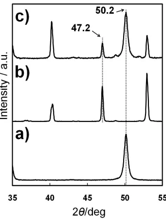
Figure 3.4 XRD patterns of a) YSZ, b) reduced Na0.8WO3-δ, and c) mixed Na0.8WO3-δ with YSZ reduced at 1023K under humidified (3% H2O)
H2. 59
Figure 3.5 XRD patterns of a) K0.5WO3-δ, b) Rb0.2WO3-δ, and c) Cs0.2WO3-δ
synthesized in humidified (3% H2O) H2 at 973 K and 1073K. 61
Figure 3.6 XRD patterns of Na0.8NbyW1-yO3-δ -YSZ composite with different Nb:W ratios (y = 0, 0.3, 0.7, 1) synthesized in humidified (3% H2O)
H2 at following temperatures: a) 973 K, and b) 1123 K. 63
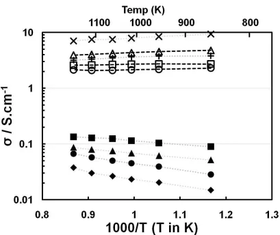
Figure 3.7 Electrical conductivities of the 40 wt. % (■) Na0.8WO3-δ-YSZ (♦) Na0.8Nb0.3W0.7O3-δ-YSZ, (●) Na0.8Nb0.7W0.3O3-δ -YSZ, and (▲) NaNbO3-δ-YSZ composites in humidified (3% H2O) H2 as a function of temperature. Data were obtained (■, ♦, ●,▲) on heating and (□ ,◊
,○ ,Δ) on cooling. 65
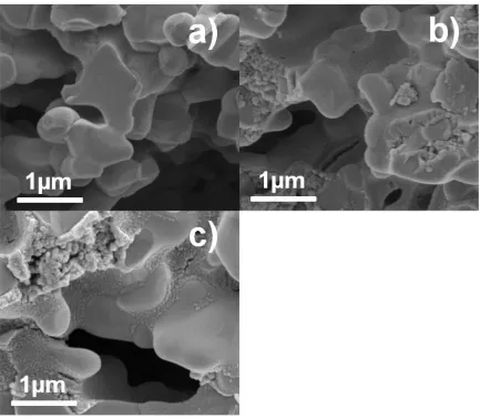
Figure 3.8 Microstructure of the (a) YSZ matrix, Na0.8WO3-δ-YSZ composite reduced at following temperatures: (b) 973 K and (c) 1123 K, d) Na0.8Nb0.3W0.7O3-δ -YSZ composite, and e) Na0.8Nb0.7W0.3O3-δ -YSZ composite reduced at 1123 K in humidified (3% H2O) H2.
67
xii (●)withoutPd catalyst, and (♦) with Pd after exposure to humidified
H2 at 1123 K, operated at 973 K under humidified (3% H2O) H2. 69
Figure 4.1 XRD patterns of Ce1-xSrxVO4-0.5x–YSZ composites with different Ce:Sr ratios (x=0, 0.3, 0.5, 0.7, 1) that were calcined in air at 973 K. The peaks labeled ● and ▲ correspond to Ce1-xSrxVO4-0.5x and▲,
respectively. 87
Figure 4.2 Plots of the position of the (200) diffraction peak as a function of x
for both Ce1-xSrxVO4-0.5x and Ce1-xCaxVO4-0.5x. 88
Figure 4.3 XRD patterns of oxidized and reduced cerium-strontium vanadate: The peaks are labeled as follows: (□) zircon Ce0.7Sr0.3VO3.85, (●)
perovskite Ce0.7Sr0.3VO3.0, and (▲) cubic YSZ. 91
Figure 4.4 Coulometric titration isotherms for (□) LaVO4, (○) PrVO4, (◊) CeVO4, (▲) Ce0.7Sr0.3VO3.85, and (■) Ce0.7Ca0.3VO3.85, at 973 K.
92
Figure 4.5 Electronic conductivities of 30 wt. % (■) LaVO3-,(▲) CeVO3-, (●) PrVO3-, (♦) SmVO3-, (+) La0.7Sr0.3VO3-, () Ce0.7Sr0.3VO3-, (□ ) La0.7Ca0.3VO3-, (Δ) Ce0.7Ca0.3VO3-, (○) Pr0.7Ca0.3VO3 - YSZ composites in humidified H2 as a function of temperature.
94
Figure 4.6 SEM micrographs of (a) the bare YSZ scaffold, and the Ce0.7Sr0.3VO3.85-YSZ composite calcined at 973 K (b) before and (c)
after reduction in humidified H2 at 973 K. 97
Figure 4.7 (a) V-i polarization curves and (b) electrochemical impedance spectra of cells with infiltrated 30 wt. % of Ce0.7Sr0.3VO3.85-YSZ anodes with (Δ) and without (▲) Pd catalyst. The cells were
operated at 973 K with humidifiedH2 fuel. 100
Figure 5.1 Panel A: Schematic of an intelligent catalyst in which metals move out of and into an oxide host lattice in response to exposure to reducing and oxidizing conditions, respectively. Panel B: Sintering of metal nanoparticles on an oxide which occurs over time for most
traditional supported metal catalysts. 110
Figure 5.2 XRD patterns of Ce1-xNixVO4-0.5x–YSZ composites that were calcined in air at 973 K for x values of 0, 0.2, 0.3, 0.4, 1. The peaks labeled▲, □ and ● correspond to YSZ, Ni2V2O7 and Ce1-xNixVO
4-0.5x, respectively. 114
Figure 5.3 Plot of the position of the (112) diffraction peak as a function of x
xiii
Figure 5.4 XRD patterns from a Ce0.8Ni0.2VO3.90 sample that was (A) oxidized at 973 K in air, (B) reduced at 973 K in humidified H2, and (C) re-oxidized in air at 973 K. The peaks are labeled as follows: (▲) cubic YSZ, (○) zircon Ce0.8Ni0.2VO3.90, (●) perovskite Ce1-xNixVO3, and
(■) metallic Ni. 117
Figure 5.5 SEM images of (a) the bare YSZ matrix, and the Ce0.8Ni0.2VO3.90 -YSZ composite (b) oxidized in air at 973 K, and (c) reduced in
humidified H2 at 973 K. 118
Figure 5.6 SEM images of of the (a) CeVO3-, (b) Ce0.8Ni0.2VO3 -, (c) Ce0.8Co0.2VO3 -, (d) Ce0.8Cu0.2VO3 - YSZ composites that had been
exposed to dry methane at 973 K for 3 h. 121
Figure 5.7 (a) V-i polarization curves and (b) electrochemical impedance spectra of cells with infiltrated 30 wt. % of (●) Ce0.8Ni0.2VO3 -, (■) Ce0.8Co0.2VO3 -, (♦) Ce0.8Cu0.2VO3 -, and (▲) CeVO3-YSZ anodes.
The cells were operated at 973 K with humidified H2 fuel. 123
Figure 5.8 Electronic conductivities of infiltrated 30 wt. % (Δ) CeVO3-, (○) Ce0.8Ni0.2VO3-, (□) Ce0.7Sr0.1Ni0.2VO3-, (■) Ce0.7Ca0.1Ni0.2VO3-, (◊)Ce0.7Sr0.3VO3 - YSZ composites in humidified H2 as a function of
temperature. 127
Figure 5.9 Maximum power density for a cell with an infiltrated 30 wt. % of Ce0.7Sr0.1Ni0.2VO3 -YSZ anode as a function of time at 973 K with humidified H2 (3% H2O) fuel. The cell was periodically subjected to a redox treatment consisting of oxidation in air for 30 min followed
by reduction in humidified H2 for 15 min, both at 973 K. 128
Figure 6.1 XRD patterns of (A) Ce0.8Sr0.1Cu0.05Co0.05VO4-δ, and (B) Ce0.8Sr0.1Cu0.05Ni0.05VO4-δ oxidized at 973 K in air. The peaks are
labeled as follows: (▲) cubic YSZ, (○) zircon
Ce0.8Sr0.1Cu0.05Co0.05VO4-δ and Ce0.8Sr0.1Cu0.05Ni0.05VO4-δ . 144
Figure 6.2 XRD patterns of (A) Ce0.8Sr0.1Cu0.05Co0.05VO3, (B) Ce0.8Sr0.1Cu0.05Ni0.05VO3, (C) Ce0.8Sr0.1Ni0.1VO3, (D) Ce0.8Sr0.1Co0.1VO3, and (E) Ce0.8Sr0.1Cu0.1VO3 reduced under humidified H2 at 973 K. The dotted lines indicate the position of the Ni, Co, and Cu metal peaks. The (▲) peaks correspond to Sr
doped-CeVO3. 145
Figure 6.3 SEM images of the (A) Ce0.8Sr0.1Cu0.1VO3-, (B) Ce0.8Sr0.1Co0.1VO3-, (C) Ce0.8Sr0.1Cu0.05Ni0.05VO3-, (D) Ce0.8Sr0.1Cu0.05Co0.05VO3-YSZ
xiv
Figure 6.4 V-i polarization curves for cells with infiltrated 30 wt. % of ( , ) Ce0.8Sr0.1Cu0.05Co0.05VO3, (- -) Ce0.8Sr0.1Co0.1VO3, ( ) Ce0.8Sr0.1Cu0.1VO3, and ( ) CeVO3 –YSZ anodes. Inset: Electrochemical impedance spectra of Ce0.8Sr0.1Cu0.05Co0.05VO3 cell measured at (A) 0.4 V and (B) 0.2 V. The cells were operated at 973
K with humidified H2 fuel. 150
Figure 6.5 Schematic of the structure of the Cu-Co particles and the effect of
polarization. 154
Figure 7.1 Overview of the deposition of Pd@CeO2 nanostructures on (A) clean YSZ(100) and (B) alkyl-siloxane functionalized YSZ(100). On clean YSZ the hydrophobic, alkyl-capped Pd@CeO2 particles are repelled by the hydrophilic OH-terminated YSZ surface, resulting in the formation of agglomerates during deposition, with further agglomeration occurring upon calcination in air. On the alky-siloxane functionalized YSZ surface, the Van der Waals interactions between the capping alkyl groups on the surface and the core-shell particles directs the formation of a monolayer film of the Pd@CeO2 particles. This Pd@CeO2 layer is highly stable and remains highly
dispersed upon calcination in air. 168
Figure 7.2 Contact angle measurements. Image of 1 µL water droplet placed on clean YSZ(100) substrate (Panel A) and silanated YSZ(100) substrate (Panel B) with tensiometry. Deposition of the TEOOS layer using the CVD process resulted in an increase in the water
contact angle from 70° to 100°. 169
Figure 7.3 AFM characterization of clean and TEOOS-treated YSZ(100). AFM topography images with representative line scans for clean (A) YSZ(100) and (B) TEOOS-treated YSZ(100) samples. The AFM image of the plasma-cleaned YSZ(100) substrate prior to silane deposition (A) shows it to be featureless with a rms roughness of 0.07 nm which is consistent with a nearly atomically flat surface. A
relatively uniform image was also obtained for the
silanated/YSZ(100) sample (B), but it contained small wave-like
features and had a rms roughness of 2.4 nm. 170
Figure 7.4 AFM topography images with representative line scans for Pd@CeO2 and Pd nanoparticles deposited on clean and
alkyl-silanated YSZ(100). Panel A corresponds to Pd@CeO2 deposited on
xv
and 1373 K (G). Comparison of the images for the Pd@CeO2 and Pd
nanoparticles clearly demonstrates the high thermal stability of the
Pd@CeO2 nanoparticles. 172
Figure 7.5 Ce(3d) XP spectra obtained from Pd@CeO2 deposited on alkyl-siloxane functionalized YSZ(100) after calcination under different conditions. The sample was calcined in air at 723 K (A) and 973 K
(B), and in ultra-high vacuum at 700 K (C). 177
Figure 7.6 CO-TPD data and schematic representation of changes in shell
morphology for oxidized and reduced Pd@CeO2/YSZ(100)
catalysts. The CO-TPD results obtained after 50 L CO dose at 260 K
on Pd@CeO2 deposited on silanated YSZ(100) calcined at 973 K in
air (A) and 700 K in vacuum (B). The y-axis in the figure corresponds to the m/e 28 mass spectrometer signal in arbitrary
units. The two spectra have been offset to facilitate comparison. 179
Figure 7.7 Reaction rate data for CH4 oxidation. Pd@CeO2 core-shell catalyst supported on (○) TEOOS-treated -Al2O3 and (Δ) TDPA-treated -Al2O3 calcined in air at 1123 K for 6 hrs prior to rate measurements.
The Pd weight loading in each catalyst was 1 %. 181
Figure 8.1 SEM images, with the schematic representation of bare YSZ matrix
(Panel A), Pd@CeO2 nanoparticles deposited on: clean YSZ porous
electrode (Panel B) and silanated YSZ porous electrode (Panel C). 2 nm un-coated Pd nanoparticles deposited on silanated YSZ porous
electrode (Panel D). All samples calcined at 973 K in air. 193
Figure 8.2 SEM images, with the schematic representation of the agglomeration of Pd@CeO2 (Panel A) and 2 nm un-coated Pd (Panel B)
nanoparticles deposited on silanated YSZ porous electrode after
samples calcined at 1373 K in air. 195
Figure 8.3 Image of hydrophobicity test with YSZ and LSCM, before and after treatment with TEOOS. 0.1 g of each powder was then placed in a test tube filled with 5 ml of H2O. 196
Figure 8.4 (A) V-i polarization curves and (B) electrochemical impedance spectra of cells with infiltrated 45 wt. % LSCM-YSZ (blue ◊) with and (red □) without treatment with TEOOS. Both the cells were then calcined in air at 723 K upon addition of 1 wt. % Pd to the TEOOS-treated LSCM anode by infiltration with aqueous solution of (NH3)4Pd(NO3)2 to enhance the catalytic activity. In order to produce the Pd phase, both the cells were then calcined in air at 723 K before
xvi
Figure 8.5 (A) V-i polarization curves and (B) electrochemical impedance spectra of cells with infiltrated 45 wt. % LSCM-YSZ after treatment
with TEOOS containing (orange □) Pd@CeO2 and (red ◊) no
catalyst. The cells were initially calcined at 723 K in air before
measurement at 973 K with humidified H2 fuel (3% H2O). 202
Figure 8.6 (A, B) V-i polarization curves and (C) electrochemical impedance spectra of cells annealed under oxidizing conditions at higher temperatures, with infiltrated 45 wt. % LSCM-YSZ after treatment
with TEOOS, containing infiltrated (Figure 8.6A) Pd@CeO2
nanoparticles annealed in air at (□) 723 K and (■) 1123 K, (Figure 8.6B) 2 nm un-coated Pd nanoparticles annealed in air at (Δ) 723 K and (▲) 1123 K. The cells were operated at 973 K with humidified
H2 fuel (3% H2O). 205
Figure 8.7 (A, B) V-i polarization curves and (C) electrochemical impedance spectra of cells annealed under reducing conditions at higher temperatures, with infiltrated 45 wt. % LSCM-YSZ after treatment
with TEOOS, containing infiltrated (Figure 8.7A) Pd@CeO2
nanoparticles (□) before 1073 K and (■) after 1073 K treatment in humidified H2, (Figure 8.7B) 2 nm un-coated Pd nanoparticles (□) before 1073 K and (■) after 1073 K treatment in humidified H2. The cells were initially calcined at 723 K in air before measurement at
973 K with humidified H2 fuel (3% H2O). 208
Figure 8.8 V-i polarization curves of with infiltrated 45 wt. % LSCM-YSZ after treatment with TEOOS, containing infiltrated (□) Pd@CeO2 and (◊) 2 nm un-coated Pd nanoparticles calcined at 723 K and 1123 K in air, and (○) no catalyst. Measurements were taken at 973 K in dry
CH4. 211
Figure 9.1 XRD patterns of La0.8Sr0.2CoxFe1-xO3 -YSZ composites that had been calcined to 1123 K with the indicated compositions. The peak positions correspond to: ●-La2Zr2O7, ■-SrZrO3, ◊-YSZ, and
∆-La0.8Sr0.2CoxFe1-xO3. 223
Figure 9.2 XRD patterns of La0.8Sr0.2CoxFe1-xO3 -YSZ composites that had been calcined to 1373 K with the indicated compositions. The peak positions correspond to: ●-La2Zr2O7, ■-SrZrO3, ◊-YSZ, and
∆-La0.8Sr0.2CoxFe1-xO3. 224
Figure 9.3 a) Performance curves and b) Electrochemical impedance spectra obtained at open circuit for fuel cells with infiltrated LSCF cathodes that had been calcined at 1123 K. The composition of the LSCF used
xvii
Figure 9.4 a) Performance curves and b) Electrochemical impedance spectra obtained at open circuit for fuel cells with infiltrated LSCF cathodes that had been calcined at 1373 K. The composition of the LSCF used
in each cell is indicated in the figure. 228
Figure 9.5 Electrochemical impedance spectra obtained at open circuit for fuel cells with infiltrated LSC, LSC20F, and LSF cathodes with (open symbols) and without (filled symbols) infiltrated SDC interlayers.
1
Chapter 1. Introduction
Summary
A general introduction on fuel cells will be discussed in this chapter. This
includes the Solid Oxide Fuel Cell (SOFC) operating principles, the cell components, the
advantages and the drawbacks of the current state-of-the-art anode materials. The goals
of this thesis will also be presented.
1.1 Motivation
Global demand for energy is rising rapidly due to the increase in industrialization
and world population. Additionally, rising concerns in the world today regarding
environmental issues have motivated the search for a cleaner, more efficient and
sustainable system for power generation. Fuel cells are electrochemical devices that are
capable of achieving very high efficiencies in the conversion of chemical to electrical
energy. In addition, Fuel cells are of great interest as they are capable of providing a
much cleaner and more consistent source of energy.
Thermal power plants are currently the most prevalent source of energy
generation. The production of electrical energy in these power plants relies on firstly
converting heat into mechanical energy which is then subsequently converted to electrical
energy. In comparison, Fuel cells are able to convert chemical energy directly to
electrical energy. Therefore, fuel cells are not limited by the Carnot cycle and are
generally significantly more efficient than electrical energy production by thermal power
2 higher temperatures to recover some of the waste heat5,7-10. The overall efficiency for the
combine heat and power (CHP) generation system can be enhanced to above 80 %4,5,8-10.
The properties and applications of many types of fuel cell are determined by the
chemical nature of the electrolyte material that is used. Most Fuel cells, for example, the
Polymer Exchange Membrane Fuel Cells (PEMFCs), rely on the conduction of protons
due to the use of the hydrated proton-conducting polymers as the electrolyte. In order for
hydrocarbons to be used as a fuel for these types of fuel cells, they must first be reformed
to H2. On the other hand, Solid Oxide Fuel Cells (SOFCs) offer a key advantage over
many other fuel cell types because of their inherent fuel flexibility. This is firstly due to
the fact that the membrane is an oxygen ion conductor and secondly because SOFC cells
operate at high temperatures (typically above 700oC)6,11,12. The high operating
temperatures accelerate electrode reaction rates, allowing SOFCs to operate on
hydrocarbon fuels after a relatively simple reforming process2,11,12. In the next sections,
the operating principles and the basic cell components of the SOFC will be discussed.
1.2 Solid Oxide Fuel Cells
1.2.1 SOFC Operating Principles
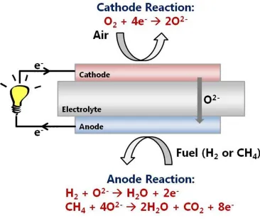
SOFC is a solid-state electrochemical device that directly converts chemical
energy to produce electrical energy through a chemical reaction between a fuel and an
oxidant. Like other fuel cells, SOFCs consist of three components: two electrodes, a
cathode and an anode, and a solid electrolyte, as shown in Figure 1.1. The two electrodes
are separated by an electrolyte membrane that allows only ionic transport from one
3 conductivity with negligible electronic conductivity. In addition, it must be dense and
leak free to separate the direct combustion of the fuel at the fuel electrode from oxygen at
the air electrode.
During the operation of a fuel cell, gas phase oxygen molecules first diffuse into
the cathode where it is electrochemically reduced by electrons (from the external circuit)
into oxygen anions as shown in Equation 1.1.
O2 (g) + 4e‾ → 2O2‾, Equation 1.1
The oxygen anions are then conducted through the ceramic electrolyte by a defect
hopping mechanism5,6 before reaching the anode. Fuel, which can be H2 or any
hydrocarbons (e.g. CO or CH4) is fed to the anode where it is oxidized by the oxygen
anions supplied from the electrolyte membrane to produce steam and/or carbon dioxide.
At the same time electrons are released to the external circuit:
H2 (g) + O2‾ → H2O (g) + 2e‾, Equation 1.2
CO (g) + O2‾ → CO2 (g) + 2e‾, Equation 1.3
in the case of hydrocarbon fuels,
4
Figure 1.1 The operating principle of a solid oxide fuel cell.
In an ideal SOFC, the driving force for oxygen ion diffusion is the difference in
the oxygen chemical potential between the air and the fuel sides of the electrolyte. This is
in turn related to the O2 fugacities at the cathode and anode. For example, the H2
oxidation reaction at open circuit would be approximately 1 V when the cell is not
loaded, as defined by the Nernst potential given in Equation 1.5:
Equation 1.5
where Vo is the equilibrium potential at standard conditions, and F is the Faraday
constant, the number of Coulombs in a mole of electrons. Multiple SOFC units can be
5
1.2.2 Three-Phase Boundary (TPB)
The microstructure of the composite electrode is one of the key factors to achieve
high performance as an ideal microstructure would offer the highest three-phase
boundary (TPB) length for electrochemical reactions13-19. As shown in Equations 1.2 to
1.4, it is apparent that the gas phase hydrogen/hydrocarbon molecules, oxygen anions
from the ((Y2O3)0.08-(ZrO2)0.92 abbreviated as YSZ) YSZ electrolyte, and the electrons
from the conductive electrode must all be present for the oxidation reaction to occur. For
example, the current standard anode material with SOFC based on YSZ as the electrolyte
is a Ni-YSZ ceramic-metallic (cermet) composite. The Ni in this composite provides
electronic conductivity and catalytic activity, while the YSZ helps maintain porosity in
the electrode and provides ionic conductivity to extend the TPB region. This concept also
applies for the cathode where the use of composite cathodes will increase the number of
oxygen reduction reactions due to the increase in TPB.
1.3 Materials for SOFC
The basic components of a SOFC comprise of the electrolyte, the anode, the
cathode and the interconnect. The criteria and current state-of-the-art materials for the
cell components of SOFC will be reviewed in the next sections. In addition, as many of
the promising oxides used for the cell components of SOFCs have a perovskite-related
6
1.3.1 Perovskite Materials
Perovskite oxide materials have a general formula of ABO3, where the A-site
contains rare-earth or alkaline-earth metals such as lanthanum (La) or strontium (Sr)
while the B-site contains transition metals such as iron (Fe), chromium (Cr), and titanium
(Ti). The A-sites (corner of the unit cell) are generally occupied by larger cations while
the B-sites (cube center) are occupied by the smaller cations.
Both A- and B-site substitutions have been investigated extensively because they
can alter the properties of the oxide including the thermal expansion coefficient, the
electronic or ionic conductivity, and the chemical stability and compatibility with other
cell components of SOFCs20,21. For example, for Fe-based compositions such as LaFeO3,
partial substitution of divalent cations like Sr or Ca for trivalent La creates oxygen
vacancies while substitution of Co for Fe results in enhanced electronic conductivity
16,20-22
. While these perovskite materials are a promising cathode material for intermediate
temperature SOFCs, unfortunately, the Fe- or Co-based perovskites are not stable at very
low oxygen partial pressures which make them unsuitable for use in the fuel electrode
operating conditions required for anode materials.
A similar strategy can be applied to design perovskite materials that are stable and
compatible for SOFC anodes. For instance, one of the most promising perovskites that
are stable under these conditions is the lanthanum-chromite perovksites which is used as
the SOFC interconnect (described in more detail in Section 1.2.3.4)23,24. In a study by
Irvine and Tao, different transition elements such as V, Mn, Fe, Co, Ni, and Cu were
7 La0.75Sr0.25Cr0.5Mn0.5O3 is not just stable in both fuel and air conditions, they also show
stable electrode performance in methane25,26.
A wide variety of perovskite oxides are being investigated for use as cell
components in SOFCs (this will be further discussed in more detail in the next sections)
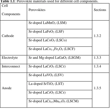
and some examples are presented in Table 1.1 below
Table 1.1:Perovskite materials used for different cell components. Cell
Components
Perovskites Sections
Cathode
Sr-doped LaMnO3 (LSM)
1.3.2 Sr-doped LaFeO3 (LSF)
Sr-doped LaCoO3 (LSCo)
Sr-doped LaCo1-yFeyO3 (LSCF)
Electrolyte Sr and Mg-doped LaGaO3 (LSGM) 1.3.3
Interconnect Sr-doped LaCrO3 (LSCr) 1.3.4
Anode
Sr-doped LaVO3 (LSV)
1.3.5 La-doped SrTiO3 (LST)
Sr-doped LaCrO3 (LSCr)
Sr-doped LaCr0.5Mn0.5O3 (LSCM)
1.3.2 Cathode (air electrode)
The air electrode operates in an oxidizing condition in which the oxygen in the
gas phase (air or pure oxygen) undergoes an oxygen reduction reaction which consumes
8 perovskite materials, Sr-doped LaMnO3 (LaxSr1-xMnO3-δ, LSM, where x is between 0.5
and 0.85)is the standard air electrode material owing to its high electronic conductivity
(~300 S/cm at 1000°C5) and activity towards the oxygen reduction reaction27,28. In
addition, LSM is both chemically (no solid state reaction) and physically (thermal
expansion match with other cell components) compatible with YSZ29.
While LSM has good electronic conductivity, the ionic conductivity of LSM is
very low (~10-8 S/cm at 800°C28), implying that the oxygen reduction reaction can only
occur at the TPB line contact between the LSM, the YSZ, and the gas phase. Therefore,
the use of composites with YSZ to increase the TPB length is required in order to achieve
high performance with LSM. In contrast to LSM, other SOFC cathodes based on the
ferrites or cobaltites, for example Sr-doped LaCoO3 (LSCo), Sr-doped LaFeO3 (LSF), or
Sr-doped LaCoxFe1-xO3 (LSCF)16 are mixed ionic and electronic conductors (MIEC). The
use of MIEC electrode materials extends the electrochemically active region by allowing
the oxygen adsorption and reduction to take place not only on the TPB sites, but also on
the perovskite bulk material16,19,30,31.
The chemical stability of composite electrodes produced by the infiltration of
LSCF into a porous YSZ scaffold was investigated as a function of the Co:Fe ratio in the
LSCF and the LSCF calcination temperature is discussed in Chapter 9. In addition, the
effectiveness of infiltrated SDC interlayers in preventing reactions at the LSCF-YSZ
interface and their influence on the overall performance of LSCF/YSZ composite
9
1.3.3 Electrolyte
SOFCs are based on the conduction of oxygen anions (O2-) from the air electrode
through the electrolyte and to the fuel electrode before reacting with the fuel to generate
an electrical voltage. YSZ is the most common electrolyte in SOFCs because of its
adequate level of ionic conductivity, negligible electronic conductivity and its high
stability in both oxidizing and reducing environments6,32. While pure ZrO2 is an insulator,
direct substitution of a trivalent metal oxide such as Y2O3 for ZrO2 results in a large
concentration of oxygen vacancies and also stabilizes the cubic fluorite structure6. The
composition of 8 mol% Y2O3 in ZrO2 was chosen because it has been shown to provide
the highest ionic conductivity as well as stabilizing the high temperature cubic phase in
ZrO2 over a wide range of SOFC operating and manufacturing temperatures6.
Another promising material for use as a SOFC electrolyte is the rare-earth doped
ceria electrolyte which also has a fluorite structure6,32,33. Among these ceria electrolytes,
the gadolinium-doped (GDC) and samarium-doped ceria (SDC) exhibit the highest
oxygen ion conductivity at a certain doping level (Ce0.8Sm0.2O1.9) and have been shown
to have good compatibility with electrodes for SOFCs compared to other electrolytes6,33.
The high ionic conductivity exhibited by the rare-earth doped ceria at intermediate
temperatures means that the operating temperature can potentially be reduced from
1000◦C to 500–800◦C6,33,34
. While the doped-ceria electrolytes are promising due to their
high ionic conductivity, there are many limitations such as difficulty in sintering these
compounds to obtain high density and also doped-ceria exhibit electrical conductivity
10
1.3.4 Interconnect
As mentioned in section 1.2.1, multiple SOFC single cells can be connected in
series to increase the voltage and power output of the system. This can be done by using
an interconnect, which provides the conductive path for electrical current to pass between
the electrodes to the external circuit. The requirements of the interconnection are the most
severe of all cell components. Firstly, the interconnect material must have good electrical
conductivity and be stable (microstructure, chemistry, and phase) under both oxidizing
and reducing environments at all cell operating temperatures since it is exposed to air or
oxygen on one side and fuel on the other side23,24. Secondly, as SOFCs operate at high
temperatures, the coefficient of thermal expansion (CTE) has to be close to the other cell
components to minimize thermal stresses. Other requirements to make a good
interconnect material also include good thermal conductivity, resistance to oxidation,
sulfidation, carburization and reaction with other cell components. It is also important
that the interconnect material has low permeability for oxygen and hydrogen, should be
easy to fabricate and have adequate mechanical strength23,24.
Only a few materials have been able to meet the rigorous requirements needed for
an interconnect. The most commonly used material for SOFC interconnects are
alkaline-earth (Ca- or Sr-) doped-LaCrO323,24. While LaCrO3 based materials appear to have met
most of these stringent requirements, they are difficult to sinter to full density making
11
1.3.5 Anode (fuel electrode)
The anode (fuel electrode) of the SOFC is the main focus in this thesis. Ni–YSZ
composites (cermets) are the most commonly used anodes in SOFC due to the high
electronic conductivity and catalytic activity of Ni, as well as their ease of fabrication. As
discussed in section 1.2.2, the electrochemical reaction (hydrogen/hydrocarbon oxidation
reaction) can occur only at the TPB line where the electronic conductor (Ni), the
oxygen-ion conductor (YSZ), and the gas phase (H2) meet13,14,19. While Ni/YSZ cermets have
been used successfully in SOFCs, they also have several limitations, including low
tolerance to sulfur impurities which are present in most fuels35, and promotion of coke
formation from hydrocarbons36-38. Other limitations include the slow loss of surface area
due to the sintering of Ni at operating temperatures, and the problematic thermal stresses
and volume instability during cycling caused by the poor redox stability of Ni39-41.
Because of these limitations, there has been extensive research focused on trying to
decrease the operating temperature34,42 and also to search for alternative anode
materials35-41,43-57. However, as the operating temperature is decreased, fuel flexibility
becomes limited because both the conversion efficiencies and tolerance to impurities will
decrease due to reduced electrode reaction rates. Therefore, the first objective in this
thesis is to search for a compatible and highly stable alternative anode material which
12
1.4 Ceramic Electrodes as Alternative Anode Materials
Overcoming the limitations of Ni cermets has motivated research into using
conductive ceramics to replace the Ni components in SOFC anodes if they were able to
provide comparable performance. Ceramic electrodes are expected to be less susceptible
to sintering and coking, be redox stable, and be more tolerant of impurities like sulfur
35-41,43-57 .
Before ceramic electrodes can be widely implemented, several important issues
need to be resolved. First and foremost, since the conductivities of most ceramics are
much lower than that of metals, ceramic electrodes with reasonable electronic
conductivities need to be developed. The conductivity problem is further exacerbated by
the fact that high-performance electrodes take the form of porous composites and the
conductivities of composites are a factor of at least 10 to 100 lower than that of the
corresponding bulk conductor58-60. The need for high conductivity in the composite
electrode is decreased by using very thin electrodes61. This strategy has been successfully
employed using infiltrated La0.8Sr0.2Cr0.5Mn0.5O3 (LSCM)49,62, La0.3Sr0.7TiO3 (LST)44,45,
and ceria63. However, the use of thin electrodes simply transfers the conduction
requirements onto the current collector. As a general rule, the electrode composite should
have a minimum conductivity of 1 S/cm3,64, the approximate conductivity of SOFC
cathodes based on composites of YSZ and Sr-doped LaMnO365. Second, most ceramics
are conductive only over a specific range of P(O2), and conductivity for SOFC anodes
must be achieved at conditions corresponding to roughly equal molar concentrations of
H2 and H2O over a wide range of temperatures. Most conductive oxides in these low P(O2)
13 avoided. A third major issue is that many conductive ceramics undergo solid-state
reactions with YSZ at the sintering temperatures typically required for forming an
electrode that is well connected to the YSZ electrolyte.
To minimize the problems of low conductivity and solid-state reactions between
components, our group has been preparing composite electrodes using infiltration
methods (the method will be discussed in more detail in Chapter 2.2)16,66-68. This
fabrication procedure involves synthesizing a porous layer of the electrolyte that has been
pre-sintered to the dense electrolyte, then infiltrating the catalytic and electronically
conductive components into the porous scaffold69. The first goal of this thesis is to search
for highly conductive ceramics that are stable and tolerant under SOFC operating
conditions. The synthesis, characterization and use of the highly conductive tungsten
bronzes and alkaline-earth doped rare-earth vanadates for SOFC anodes are investigated
and described in Chapter 3 and 4, respectively.
1.5 Approaches to Mitigate Metal Catalyst Deactivation
While promising results have been obtained with ceramic-based anodes, these
anodes unfortunately have relatively low catalytic activity for oxidation reactions. This
results in high electrode overpotentials unless the anodes are decorated with nanoparticles
of a highly catalytic metal (e.g. Ni, Pt, or Pd)45,48,52-54,62,69-76. The catalytic metals are
generally added using standard wet infiltration techniques.
Due to the high operating temperatures, deactivation of the metal catalyst by
sintering and/or coking is a severe problem as loss of metal surface area due to sintering
14 develop approaches to mitigate the metal catalyst deactivation. This can be achieved by:
1) designing a catalyst that is resistant to coking and sintering and 2) developing a new
method for catalyst deposition. Two approaches aimed at mitigating the metal catalyst
deactivation are presented in chapters 5 to 8.
The first approach involved synthesizing a self-regenerating, “smart” catalyst, in
which Co, Cu, or Ni were inserted into the B-site of a perovskite oxide under oxidizing
conditions and then brought back to the surface under reducing conditions. This restores
lost surface area of sintered metal particles through an oxidation/reduction cycle. The
physical and electrochemical properties of cerium vanadates in which a portion of the
cerium cations have been substituted with transition metals (Ce1-xTMxVO4-0.5x, TM = Ni,
Co, Cu) were investigated and is described in Chapter 5. In order to produce catalytic
materials that have relatively high hydrocarbon tolerance using the exsolution method,
the cerium cations are substituted with mixed transition metal systems
(Ce0.8Sr0.1Cu0.05TM0.05VO4-0.5x, TM = Ni or Co) and their suitability for use in SOFC
anodes are assessed in Chapter 6.
The second strategy involves depositing novel highly active and thermally stable
Pd@CeO2 core-shell nanostructure catalysts onto a substrate surface which had been
chemically modified to anchor the nanoparticles. This work is described in Chapter 7.
The catalyst deposited onto the chemically modified, hydrophobic surface is shown to be
uniform and well dispersed. Furthermore they exhibit excellent thermal stability to
temperatures as high as 1373 K. Similar metal catalyst deposition method was also
employed to access their suitability for use in SOFC anodes and this work is described in
15
1.6 References
1 Goodenough, J. B. & Huang, Y. H. Alternative anode materials for solid oxide
fuel cells. J Power Sources 173, 1-10, doi:DOI 10.1016/j.jpowsour.2007.08.011
(2007).
2 Fergus, J. W. Oxide anode materials for solid oxide fuel cells. Solid State Ionics
177, 1529-1541, doi:DOI 10.1016/j.ssi.2006.07.012 (2006).
3 Cowin, P. I., Petit, C. T. G., Lan, R., Irvine, J. T. S. & Tao, S. W. Recent Progress
in the Development of Anode Materials for Solid Oxide Fuel Cells. Adv Energy
Mater 1, 314-332, doi:DOI 10.1002/aenm.201100108 (2011).
4 Choudhury, A., Chandra, H. & Arora, A. Application of solid oxide fuel cell
technology for power generation-A review. Renew Sust Energ Rev 20, 430-442,
doi:DOI 10.1016/j.rser.2012.11.031 (2013).
5 Minh, N. Q. Ceramic Fuel-Cells. J Am Ceram Soc 76, 563-588, doi:DOI
10.1111/j.1151-2916.1993.tb03645.x (1993).
6 Fergus, J. W. Electrolytes for solid oxide fuel cells. J Power Sources 162, 30-40,
doi:DOI 10.1016/j.jpowsour.2006.06.062 (2006).
7 Granovskii, M., Dincer, I. & Rosen, M. A. Performance comparison of two
combined SOFC-gas turbine systems. J Power Sources 165, 307-314, doi:DOI
10.1016/j.jpowsour.2006.11.069 (2007).
8 Baniasadi, E. & Alemrajabi, A. A. Fuel cell energy generation and recovery cycle
analysis for residential application. Int J Hydrogen Energ 35, 9460-9467, doi:DOI
16 9 Chan, S. H., Ho, H. K. & Tian, Y. Multi-level modeling of SOFC-gas turbine
hybrid system. Int J Hydrogen Energ 28, 889-900, doi:Pii
S0360-3199(02)00160-X, Doi 10.1016/S0360-3199(02)00160-X (2003).
10 Chan, S. H., Ho, H. K. & Tian, Y. Modelling of simple hybrid solid oxide fuel
cell and gas turbine power plant. J Power Sources 109, 111-120, doi:Pii
S0378-7753(02)00051-4, Doi 10.1016/S0378-7753(02)00051-4 (2002).
11 Gorte, R. J., Vohs, J. M. & McIntosh, S. Recent developments on anodes for
direct fuel utilization in SOFC. Solid State Ionics 175, 1-6, doi:DOI
10.1016/j.ssi.2004.09.036 (2004).
12 McIntosh, S. & Gorte, R. J. Direct hydrocarbon solid oxide fuel cells. Chem Rev
104, 4845-4865, doi:Doi 10.1021/Cr020725g (2004).
13 de Boer, B., Gonzalez, M., Bouwmeester, H. J. M. & Verweij, H. The effect of
the presence of fine YSZ particles on the performance of porous nickel electrodes.
Solid State Ionics 127, 269-276, doi:Doi 10.1016/S0167-2738(99)00299-4 (2000).
14 Bieberle, A. & Gauckler, L. J. Reaction mechanism of Ni pattern anodes for solid
oxide fuel cells. Solid State Ionics 135, 337-345, doi:Doi
10.1016/S0167-2738(00)00462-8 (2000).
15 Mogensen, M., Jensen, K. V., Jorgensen, M. J. & Primdahl, S. Progress in
understanding SOFC electrodes. Solid State Ionics 150, 123-129, doi:Pii
S0167-2738(02)00269-2, Doi 10.1016/S0167-2738(02)00269-2 (2002).
16 Vohs, J. M. & Gorte, R. J. High-Performance SOFC Cathodes Prepared by
17 17 Herbstritt, D., Weber, A. & Ivers-Tiffee, E. Modelling and DC-polarisation of a
three dimensional electrode/electrolyte interface. J Eur Ceram Soc 21, 1813-1816,
doi:Doi 10.1016/S0955-2219(01)00121-2 (2001).
18 Kim, J. W., Virkar, A. V., Fung, K. Z., Mehta, K. & Singhal, S. C. Polarization
effects in intermediate temperature, anode-supported solid oxide fuel cells. J
Electrochem Soc 146, 69-78, doi:Doi 10.1149/1.1391566 (1999).
19 Tanner, C. W., Fung, K. Z. & Virkar, A. V. The effect of porous composite
electrode structure on solid oxide fuel cell performance .1. Theoretical analysis. J
Electrochem Soc 144, 21-30, doi:Doi 10.1149/1.1837360 (1997).
20 Ren, Y. Y., Kungas, R., Gorte, R. J. & Deng, C. S. The effect of A-site cation (Ln
= La, Pr, Sm) on the crystal structure, conductivity and oxygen reduction
properties of Sr-doped ferrite perovskites. Solid State Ionics 212, 47-54, doi:DOI
10.1016/j.ssi.2012.02.028 (2012).
21 Sogaard, M., Hendriksen, P. V. & Mogensen, M. Oxygen nonstoichiometry and
transport properties of strontium substituted lanthanum ferrite. J Solid State Chem
180, 1489-1503, doi:DOI 10.1016/j.jssc.2007.02.012 (2007).
22 Waernhus, I., Grande, T. & Wiik, K. Electronic properties of polycrystalline
LaFeO3. Part II: Defect modelling including Schottky defects. Solid State Ionics
176, 2609-2616, doi:DOI 10.1016/j.ssi.2005.07.014 (2005).
23 Fergus, J. W. Lanthanum chromite-based materials for solid oxide fuel cell
interconnects. Solid State Ionics 171, 1-15, doi:DOI 10.1016/j.ssi.2004.04.010
18 24 Zhu, W. Z. & Deevi, S. C. Development of interconnect materials for solid oxide
fuel cells. Mat Sci Eng a-Struct 348, 227-243, doi:Pii S0921-5093(02)00736-0,
Doi 10.1016/S0921-5093(02)00736-0 (2003).
25 Tao, S. W. & Irvine, J. T. S. A redox-stable efficient anode for solid-oxide fuel
cells. Nat Mater 2, 320-323, doi:Doi 10.1038/Nmat871 (2003).
26 Tao, S. W., Irvine, J. T. S. & Plint, S. M. Methane oxidation at redox stable fuel
cell electrode La0.75Sr0.25Cr0.5Mn0.5O3-delta. J Phys Chem B 110, 21771-21776,
doi:Doi 10.1021/Jp062376q (2006).
27 Huang, Y. Y., Vohs, J. M. & Gorte, R. J. Characterization of LSM-YSZ
composites prepared by impregnation methods. J Electrochem Soc 152,
A1347-A1353, doi:Doi 10.1149/1.1926669 (2005).
28 Ji, Y., Kilner, J. A. & Carolan, M. F. Electrical properties and oxygen diffusion in
yttria-stabilised zirconia (YSZ)-La0.8Sr0.2MnO3 +/-delta (LSM) composites. Solid
State Ionics 176, 937-943, doi:DOI 10.1016/j.ssi.2004.11.019 (2005).
29 Koh, J. H., Kang, B. S., Lim, H. C. & Yoo, Y. S. Thermodynamic analysis of
carbon deposition and electrochemical oxidation of methane for SOFC anodes.
Electrochem Solid St 4, A12-A15, doi:Doi 10.1149/1.1339237 (2001).
30 Adler, S. B. Factors governing oxygen reduction in solid oxide fuel cell cathodes.
Chem Rev 104, 4791-4843, doi:Doi 10.1021/Cr020724o (2004).
31 Bidrawn, F., Kungas, R., Vohs, J. M. & Gorte, R. J. Modeling Impedance
Response of SOFC Cathodes Prepared by Infiltration. J Electrochem Soc 158,
19
32 Amado, R. S., Malta, L. F. B., Garrido, F. M. S. & Medeiros, M. E. Solid oxide
fuel cells: Materials, components and configurations. Quim Nova 30, 189-197
(2007).
33 Nesaraj, A. S. Recent developments in solid oxide fuel cell technology - a review.
J Sci Ind Res India 69, 169-176 (2010).
34 Tarancon, A. Strategies for Lowering Solid Oxide Fuel Cells Operating
Temperature. Energies 2, 1130-1150, doi:Doi 10.3390/En20401130 (2009).
35 Matsuzaki, Y. & Yasuda, I. The poisoning effect of sulfur-containing impurity
gas on a SOFC anode: Part I. Dependence on temperature, time, and impurity
concentration. Solid State Ionics 132, 261-269 (2000).
36 Kim, H., Lu, C., Worrell, W. L., Vohs, J. M. & Gorte, R. J. Cu-Ni cermet anodes
for direct oxidation of methane in solid-oxide fuel cells. J Electrochem Soc 149,
A247-A250, doi:10.1149/1.1445170 (2002).
37 Toebes, M. L., Bitter, J. H., van Dillen, A. J. & de Jong, K. P. Impact of the
structure and reactivity of nickel particles on the catalytic growth of carbon
nanofibers. Catal Today 76, 33-42 (2002).
38 Toh, C. H., Munroe, P. R., Young, D. J. & Foger, K. High temperature carbon
corrosion in solid oxide fuel cells. Mater High Temp 20, 129-136 (2003).
39 Huang, Y. H., Dass, R. I., Denyszyn, J. C. & Goodenough, J. B. Synthesis and
characterization of Sr2MgMoO6-delta - An anode material for the solid oxide fuel
20 40 Sarantaridis, D. & Atkinson, A. Redox cycling of Ni-based solid oxide fuel cell
anodes: A review. Fuel Cells 7, 246-258, doi:DOI 10.1002/fuce.200600028
(2007).
41 Sfeir, J., van Herle, J. & McEvoy, A. J. Stability of calcium substituted lanthanum
chromites used as SOFC anodes for methane oxidation. J Eur Ceram Soc 19,
897-902 (1999).
42 Wachsman, E. D. & Lee, K. T. Lowering the Temperature of Solid Oxide Fuel
Cells. Science 334, 935-939, doi:DOI 10.1126/science.1204090 (2011).
43 Gross, M. D. et al. Redox Stability of SrNb(x)Ti(1-x)O(3)-YSZ for Use in SOFC
Anodes. J Electrochem Soc 156, B540-B545, doi:10.1149/1.3078406 (2009).
44 Kim, G., Gross, M. D., Wang, W., Vohs, J. M. & Gorte, R. J. SOFC anodes based
on LST-YSZ composites and on Y0.04Ce0.48Zr0.48O2. J Electrochem Soc 155,
B360-B366, doi:10.1149/1.2840473 (2008).
45 Lee, S., Kim, G., Vohs, J. M. & Gorte, R. J. SOFC anodes based on infiltration of
La0.3Sr0.7TiO3. J Electrochem Soc 155, B1179-B1183, doi:Doi 10.1149/1.2976775
(2008).
46 Neagu, D. & Irvine, J. T. S. Structure and Properties of La(0.4)Sr(0.4)TiO(3)
Ceramics for Use as Anode Materials in Solid Oxide Fuel Cells. Chem Mater 22,
5042-5053, doi:Doi 10.1021/Cm101508w (2010).
47 Vincent, A., Luo, J. L., Chuang, K. T. & Sanger, A. R. Effect of Ba doping on
performance of LST as anode in solid oxide fuel cells. J Power Sources 195,
21
48 Babaei, A., Zhang, L., Tan, S. L. & Jiang, S. P. Pd-promoted
(La,Ca)(Cr,Mn)O(3)/GDC anode for hydrogen and methane oxidation reactions of
solid oxide fuel cells. Solid State Ionics 181, 1221-1228, doi:DOI
10.1016/j.ssi.2010.06.042 (2010).
49 Kim, G., Corre, G., Irvine, J. T. S., Vohs, J. M. & Gorte, R. J. Engineering
composite oxide SOFC anodes for efficient oxidation of methane. Electrochem
Solid St 11, B16-B19, doi:10.1149/1.2817809 (2008).
50 van den Bossche, M., Matthews, R., Lichtenberger, A. & McIntosh, S. Insights
Into the Fuel Oxidation Mechanism of La(0.75)Sr(0.25)Cr(0.5)Mn(0.5)O(3-delta) SOFC
Anodes. J Electrochem Soc 157, B392-B399, doi:Doi 10.1149/1.3288374 (2010).
51 Zhu, X. B. et al. A comparison of La(0.75)Sr(0.25)Cr(0.5)Mn(0.5)O(3-delta) and Ni
impregnated porous YSZ anodes fabricated in two different ways for SOFCs.
Electrochim Acta 55, 3932-3938, doi:DOI 10.1016/j.electacta.2010.02.028 (2010).
52 Bierschenk, D. M. et al. Pd-substituted (La,Sr)CrO(3-delta)-Ce(0.9)Gd(0.1)O(2-delta)
solid oxide fuel cell anodes exhibiting regenerative behavior. J Power Sources
196, 3089-3094, doi:DOI 10.1016/j.jpowsour.2010.12.050 (2011).
53 Adijanto, L., Kungas, R., Park, J., Vohs, J. M. & Gorte, R. J. SOFC anodes based
on infiltration of tungsten bronzes. Int J Hydrogen Energ 36, 15722-15730,
doi:DOI 10.1016/j.ijhydene.2011.09.059 (2011).
54 Smith, B. H. & Gross, M. D. A Highly Conductive Oxide Anode for Solid Oxide
Fuel Cells. Electrochem Solid St 14, B1-B5, doi:10.1149/1.3505101 (2011).
55 Adijanto, L., Padmanabhan, V. B., Holmes, K. J., Gorte, R. J. & Vohs, J. M.
22 vanadates. J Solid State Chem 190, 12-17, doi:DOI 10.1016/j.jssc.2012.01.065
(2012).
56 Adijanto, L., Padmanabhan, V. B., Kungas, R., Gorte, R. J. & Vohs, J. M.
Transition metal-doped rare earth vanadates: a regenerable catalytic material for
SOFC anodes. J Mater Chem 22, 11396-11402, doi:Doi 10.1039/C2jm31774e
(2012).
57 Adijanto, L., Padmanabhan, V. B., Gorte, R. J. & Vohs, J. M.
Polarization-Induced Hysteresis in CuCo-Doped Rare Earth Vanadates SOFC Anodes. J
Electrochem Soc 159, F751-F756, doi:Doi 10.1149/2.042211jes (2012).
58 Fang, X. H., Zhu, G. Y., Xia, C. R., Liu, X. Q. & Meng, G. Y. Synthesis and
properties of Ni-SDC cermets for IT-SOFC anode by co-precipitation. Solid State
Ionics 168, 31-36 (2004).
59 Park, J. S. et al. A high-performance solid oxide fuel cell anode based on
lanthanum strontium vanadate. J Power Sources 196, 7488-7494, doi:DOI
10.1016/j.jpowsour.2011.05.028 (2011).
60 Zhu, W. Z. & Deevi, S. C. A review on the status of anode materials for solid
oxide fuel cells. Mat Sci Eng a-Struct 362, 228-239,
doi:10.1016/S0921-5093(03)00620-8 (2003).
61 Gross, M. D., Vohs, J. M. & Gorte, R. J. A strategy for achieving high
performance with SOFC ceramic anodes. Electrochem Solid St 10, B65-B69,
23 62 Kim, G. et al. Investigation of the Structural and Catalytic Requirements for
High-Performance SOFC Anodes Formed by Infiltration of LSCM. Electrochem
Solid St 12, B48-B52, doi:10.1149/1.3065971 (2009).
63 Kim, G., Vohs, J. M. & Gorte, R. J. Enhanced reducibility of ceria-YSZ
composites in solid oxide electrodes. J Mater Chem 18, 2386-2390, doi:Doi
10.1039/B718931a (2008).
64 Atkinson, A. et al. Advanced anodes for high-temperature fuel cells. Nat Mater 3,
17-27, doi:10.1038/nmat1040 (2004).
65 He, H. P. et al. Low-temperature fabrication of oxide composites for solid-oxide
fuel cells. J Am Ceram Soc 87, 331-336 (2004).
66 Adijanto, L., Kungas, R., Bidrawn, F., Gorte, R. J. & Vohs, J. M. Stability and
performance of infiltrated La0.8Sr0.2CoxFe1-xO3 electrodes with and without
Sm0.2Ce0.8O1.9 interlayers. J Power Sources 196, 5797-5802, doi:DOI
10.1016/j.jpowsour.2011.03.022 (2011).
67 Huang, Y. Y., Vohs, J. M. & Gorte, R. J. Fabrication of Sr-doped LaFeO(3)YSZ
composite cathodes. J Electrochem Soc 151, A646-A651, doi:10.1149/1.1652053
(2004).
68 Wang, W. S., Gross, M. D., Vohs, J. M. & Gorte, R. J. The stability of LSF-YSZ
electrodes prepared by infiltration. J Electrochem Soc 154, B439-B445, doi:Doi
10.1149/1.2709510 (2007).
69 Gorte, R. J., Park, S., Vohs, J. M. & Wang, C. H. Anodes for direct oxidation of
24 70 Kobsiriphat, W., Madsen, B. D., Wang, Y., Marks, L. D. & Barnett, S. A.
La(0.8)Sr(0.2)Cr(1-x)Ru(x)O(3-delta)-Gd(0.1)Ce(0.9)O(1.95) solid oxide fuel cell anodes: Ru
precipitation and electrochemical performance. Solid State Ionics 180, 257-264,
doi:DOI 10.1016/j.ssi.2008.12.022 (2009).
71 Kim, J. S., Nair, V. V., Vohs, J. M. & Gorte, R. J. A study of the methane
tolerance of LSCM-YSZ composite anodes with Pt, Ni, Pd and ceria catalysts.
Scripta Mater 65, 90-95, doi:DOI 10.1016/j.scriptamat.2010.06.016 (2011).
72 Bi, Z. H. & Zhu, J. H. Effect of Current Collecting Materials on the Performance
of the Double-Perovskite Sr(2)MgMoO(6-delta) Anode. J Electrochem Soc 158,
B605-B613, doi:10.1149/1.3569754 (2011).
73 Gross, M. D., Vohs, J. M. & Gorte, R. J. An examination of SOFC anode
functional layers based on ceria in YSZ. J Electrochem Soc 154, B694-B699,
doi:10.1149/1.2736647 (2007).
74 Xiao, G. L., Jin, C., Liu, Q., Heyden, A. & Chen, F. L. Ni modified ceramic
anodes for solid oxide fuel cells. J Power Sources 201, 43-48, doi:DOI
10.1016/j.jpowsour.2011.10.103 (2012).
75 Wang, Y., Madsen, B. D., Kobsiriphat, W., Barnett, S. A. & Marks, L. D.
Electron microscopy study of novel ru doped La(0.8)Sr(0.2)CrO(3) as anode materials
for Solid Oxide Fuel Cells (SOFCs). Microsc Microanal 13, 100-101, doi:Doi
10.1017/S1431927607075125 (2007).
76 Madsen, B. D., Kobsiriphat, W., Wang, Y., Marks, L. D. & Barnett, S. A.
25 anodes. J Power Sources 166, 64-67, doi:DOI 10.1016/j.jpowsour.2006.12.080
26
Chapter 2. Experimental Techniques
Summary
This section will describe the experimental methods used for materials synthesis,
as well as the methods used to characterize the properties of the candidate materials.
2.1 Materials Synthesis
2.1.1 Mixed Oxides
The mixed oxides were prepared using the Pechini Method in order to produce the
desired phases at lower temperatures. In this method, the appropriate amounts of each
nitrate precursor are dissolved in an aqueous solution together with citric acid (Fisher
Scientific) in a 1:1 molar ratio. Citric acid acts as a complexing agent to aid in the
formation of a more homogeneous solid mixture of the constituent cations after
precipitation from solution. Without the complexing agent, larger domains of the pure
oxides are formed, requiring higher calcination temperatures in order to allow
interdiffusion of the cations into the more thermodynamically stable, mixed oxide. After
forming the solid mixture from solution, the precursor was dried and the resulting powder
was calcined in air to the desired temperature.
2.1.2 Pd@CeO2 Core-Shell Nanostructures
The synthesis of the Pd@CeO2 core-shell structures is described in detail by
Cargnello, et al.1,2 and made use of Pd nanoparticles that were stabilized in