Vol. 04, Issue 03 (March. 2014), ||V1|| PP 33-38
Method of Unipolar Digital to Digital Encoding Data
Transmission
Nuha Abdelmageed Tawfig Khalil1, Abdelrasoul Jabar Alzubaidi2
1
Computer Department, 2 Electronics Engineering School
1
Aljouf University, 2 Sudan University of Science and technology
1
Skaka – Saudi Arabia, 2Khartoum – Sudan
Abstract: - Line encoding is the method used to represent the digital information on the media. A pattern, that uses either voltage or current, is used to represent the 1s and 0s of the digital signal on the transmission link. Common types of line encoding methods used in data communications are: Unipolar line encoding, Polar line encoding, Bipolar line encoding and Manchester line encoding. This paper proposed the method of unipolar digital to digital encoding data transmission using latch SN 74373, amplifier ULN 2003-500 m A, solid state relay, computer and Turbo C++ program language (TC++).
Keywords: - Unipolar, Encoding, Digital to Digital, Latch SN 74373, Amplifier ULN 2003-500 m A, Solid State Relay.
I. INTRODUCTION
A computer network is used for communication of data from one station to another station in the network [1]. Data and signals are two of the basic building blocks of any computer network. Data must be encoded into signals before it can be transported across communication media [2]. Encoding means conversion of data into bit stream [3]. There are different encoding schemes available:
Analog-to-Digital
Digital-to-Analog
Analog-to-Analog
Digital-to-Digital
Digital-to-Digital
Digital-to-Digital encoding is the representation of digital information by a digital signal, Fig. 1 show digital-to-digital encoding. There are basically following types of digital to-digital encoding available like [4]:
Fig. 1 : Digital-to-Digital encoding
Unipolar
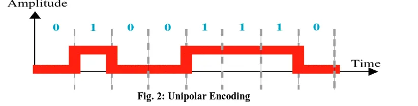
Unipolar encoding uses only one level of value. 1's are encoded as positive value and 0's are encoded as zero value, Fig. 2 show unipolar encoding [5 ].
Polar
Polar encoding uses two levels positive and negative of amplitude. Types of polar encoding :
Return to Zero( RZ )
Return to Zero use three value(positive, negative, zero) : 1 : positive-to-zero, 0 : negative-to-zero. Fig. 3 show Return to Zero encoding.
Fig. 3: Return to Zero Encoding
Non Return to Zero ( NRZ )
Types of Non Return to Zero :
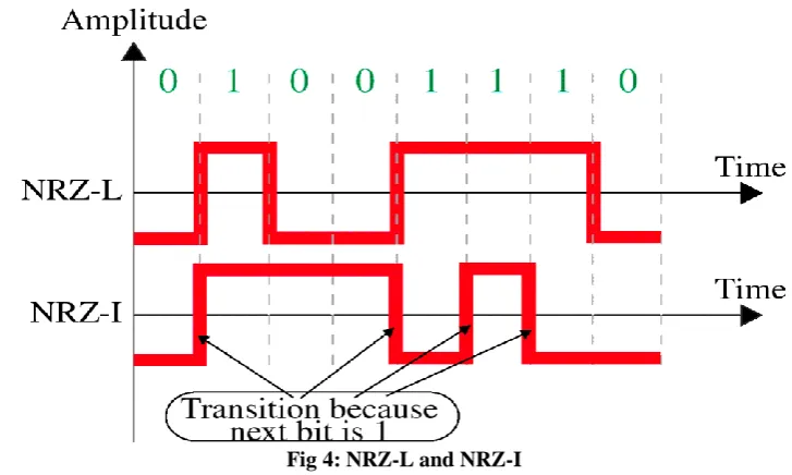
Non return to Zero-Level (NRZ-L) : the level of the signal is dependent upon the state of the bit. Fig. 4 show Non Return to Zero - Level encoding.
Non return to Zero-Inverted (NRZ-I): the signal is inverted if a 1 is encountered. Fig. 4 show Non Return to Zero - Inverted encoding.
Fig 4: NRZ-L and NRZ-I
Biphase
Biphase is implemented in two different ways :
Manchester
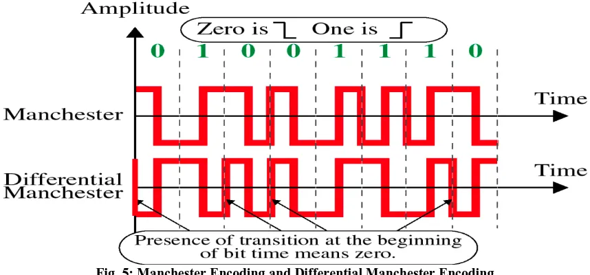
In Manchester encoding "1" is transmitted as 0 in the first half of the clock and 1 in the second half of the clock. And "0" is transmitted as 1 in the first half of the clock and 0 in the second half of the clock [6]. Fig. 5 show Manchester encoding.
Differential Manchester
opposite to the last half of the previous bit's signal. That is, a zero bit is indicated by a transition at the beginning of the bit [7]. Fig. 5 show Differential Manchester encoding.
Fig. 5: Manchester Encoding and Differential Manchester Encoding
Bipolar.
Bipolar used three voltage levels(positive, negative, zero). zero level : binary 0, positive and negative voltage : 1(alternate). Types of bipolar encoding :
Alternate Mark Inversion (AMI)
In this code, a binary 0 is encoded as zero volts, whereas a binary 1 is encoded alternately as a positive voltage or a negative voltage [8]. Fig. 6 show Alternate Mark Inversion.
Fig. 6: Alternate Mark Inversion
Bipolar 8-Zero Substitution (B8ZS)
Is the convention adopted in North America to provide synchronization of long strings of 0s. Fig. 7 show Bipolar 8-Zero Substitution.
Fig. 7: Bipolar 8-Zero Substitution
High-Density Bipolar 3 (HDB3)
Fig.8 : High-Density Bipolar 3
II. METHODOLOGY
The circuit diagram for the method of unipolar digital to digital encoding data transmission consists of two elements :
A. Hardware components :
Latch SN 74373 : used to store signal.
Amplifier ULN 2003-500 m A : used to increase the power of a signal.
Solid state Relay : used ON-OFF control device.
Lab link : used to connect latch SN 74373 to the computer.
Computer : used to install turbo C++ program language.
B. Software :
Turbo C++ program language: used to send the signal.
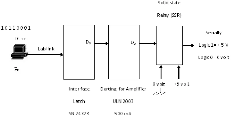
The circuit diagram for the paper consists of latch SN 74373, amplifier ULN 2003-500 m A, solid state relay, computer and Turbo C++ program language. The interconnection for the circuit is shown in Fig.9.
Fig. 9 : block diagram for the circuit
III. RESULTS
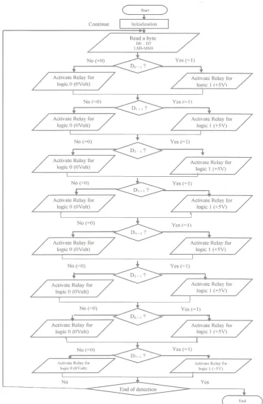
The flowchart of the method of unipolar digital to digital encoding data transmission is shown in Fig. 10.
Fig. 10 : flowchart of the Method of Unipolar Digital to Digital Encoding Data Transmission
IV. CONCLUSION
REFERENCES
[1] http://nptel.iitk.ac.in/courses/Webcourse-contents/IIT%20Kharagpur/ Computer%20networks/pdf/M2L4.pdf
[2] ftp://mail.im.tku.edu.tw/Prof_Liang/DataComunication%26ComputerNetwork/5th%20Edi/Inst ructor's%20Manual_PDF/9781423903031_IM_PDF/9781423903031_IM_ch02.pdf.
[3] http://wiki.answers.com/Q/Definition_of_digital_signal_encoding#slide=2
[4] http://ecomputernotes.com/computernetworkingnotes/communication-networks/encoding-techniques-and-codec
[5]
http://books.google.com.sa/books?id=7LBkot3T7H0C&pg=SA1-PA35&lpg=SA1-PA35&dq=types+of+polar+encoding&source=bl&ots=QF6OUTcnnz&sig=wmjADVymItXVJ
QHY0hTwAyuH-QY&hl=ar&sa=X&ei=sorFUqiXDIWmhAfQsIHwAg&ved=0CHIQ6AEwCTgK#v=onepage &q=types%20of%20polar%20encoding&f=false