e-ISSN: 2250-3021, p-ISSN: 2278-8719 Vol. 3, Issue 6 (June. 2013), ||V3|| PP 17-25
Performance Analysis of DWT operated DVR using Sinusoidal
and Selective Harmonic PWM Techniques
R.Saranya
1, M.Maheswari
2, V.Priya
31
PG Scholar, EEE Department, SNS college of Engineering, Coimbatore, India
2
Associate Professor, EEE Department, SNS College of Engineering, Coimbatore, India.
3
PG Scholar, EEE Department, SNS college of Engineering, Coimbatore, India
Abstract: The Quality of the output power from the utilities has become a major concern of the modern industries. The power quality associated problems are voltage sag, surge, flicker, voltage imbalance, interruptions and harmonic problems. The power quality problems may cause problems to the industries ranging from malfunctioning of equipment to complete plant shut down. It has been identified that power quality can be degraded both due to utility side abnormalities as well as the customer side abnormalities. Voltage sag and swells in the medium and low voltage distribution grid are considered to be the most frequent type of power quality problems based on recent power quality studies. Their impact on sensitive loads is severe. Different solutions have been developed to protect sensitive loads against such disturbances but Dynamic Voltage Restorer (DVR) is considered to be the most efficient and effective solution. In order to mitigate these disturbances, they must be detected properly. The detection can be done by conventional techniques like Fourier Transform (FT), Phase Locked Loop (PLL) and Peak detection method. But Discrete Wavelet Transform (DWT) is efficient as it easily and rapidly provides information about the voltage sag depth and phase shift. It also localizes both frequency and time at the same time. This project presents an implementation of the DWT using Butterworth passive LC filters for operating a Dynamic Voltage Restorer (DVR) system.
Butterworth LC filter is used to provide monotonic and ripple free magnitude response. Thus the Power quality of the proposed system is expected to improve. Two pulse width modulation –based control techniques, viz. sinusoidal PWM and selective harmonic elimination PWM ,are presented for controlling the switching pulses to the inverter used in the DVR system .The Simulation study of selective harmonic elimination PWM technique for DVR is compared with sinusoidal PWM. Simulations are carried out using MATLAB/SIMULINK.
Keywords: Dynamic Voltage Restorer, Phase Locked Loop, Selective Harmonic Elimination Pulse Width Modulation, Discrete Wavelet Transform.
I. INTRODUCTION
significant performance improvements in detecting and responding effectively and accurately to different types of abnormal operating conditions.
II. DISCRETE WAVELET TRANSFORM
Wavelet analysis is an exciting new method for solving difficult problems in mathematics, physics and engineering with modern applications as diverse as wave propagation, data compression, signal processing, image processing, pattern recognition, computer graphics, detection of aircraft and submarines. Wavelets allow complex information such as music, speech, images and patterns to be decomposed into elementary forms at different positions and scales and subsequently reconstructed with high precision. Wavelet transforms allow the components of a non-stationary signal to be analyzed. Wavelets also allow filters to be constructed for stationary and non-stationary signals [5].
The Discrete Wavelet Transform (DWT), which is based on sub-band coding is found to yield a fast computation of wavelet transform. It is easy to implement and reduces the computation time and resources required. A technique similar to sub-band coding was developed which was named pyramidal coding. Later many improvements were made to these coding schemes which resulted in efficient MRA schemes. In Continuous Wavelet Transform (CWT), the signals are analyzed using a set of basis functions which relate to each other by simple scaling and translation. In the case of DWT, a time-scale representation of the digital signal is obtained using digital filtering techniques [14]. The signal to be analyzed is passed through filters with different cutoff frequencies at different scales [11]. The fundamental approach to realize the DWT is by digital filtering techniques, where the analysed signal is passed through stages of digital half band filters and downsampled at the end of each stage. These successive filtering and downsampling operations are known as the Mallat algorithm. The significance of the Mallat algorithm lies in the manner it connects the MRA to discrete time filtering operations.
In numerical analysis and functional analysis, a discrete wavelet transform (DWT) is any wavelet transform for which the wavelets are discretely sampled. As with other wavelet transforms, a key advantage it has over Fourier transforms is temporal resolution, it captures both frequency and location information (location in time) [10]. The most commonly used set of DWT was formulated by the Belgian mathematician Ingrid Daubechies in 1988. This formulation is based on the use of recurrence relations to generate progressively finer discrete samplings of an implicit mother wavelet function.
III. MULTI-RESOLUTION ANALYSIS USING FILTER BANKS
Filters are one of the most widely used signal processing functions. Wavelets can be realized by iteration of filters with rescaling. The resolution of the signal is a measure of the amount of detail information in the signal which is determined by the filtering operations. Its scale is determined by up sampling and down sampling (subsampling) operation. The DWT is computed by successive low pass and high pass filtering of the discrete time-domain signal as shown in Fig 1.
Fig.1 Three level decomposition tree
This is called the Mallat algorithm or Mallat-tree decomposition. Its significance is in the manner it connects the continuous-time mutiresolution to discrete-time filters. In the Fig.1 the signal is denoted by the sequence x [n], where n is an integer. The low pass filter is denoted by G0 while the high pass filter is denoted by H0. At each level, the high pass filter produces detail information d[n], while the low pass filter associated with scaling function produces coarse approximations a[n].
half band low pass filtering removes half of the frequencies and thus halves the resolution, the decimation by 2 doubles the scale.
With this approach, the time resolution becomes arbitrarily well at high frequencies, while the frequency resolution becomes arbitrarily good at low frequencies. The time frequency plane is thus resolved. The filtering and decimation process is continued until the desired level is reached. The maximum number of levels depends on the length of the signal. The DWT of the original signal is then obtained by concatenating all the coefficients a[n] and d[n], starting from the last level of decomposition.
The above operation can be represented in mathematical form. The DWT of a signal is calculated by passing it through a series of filters [12]. First the samples are passed through a low pass filter.
Y[n] = (x * g ) [n] =∑ x[k] g[n-k] (1)
The signal is also decomposed simultaneously using a high-pass filter. The outputs are giving the detail coefficients (from the high-pass filter) and approximation coefficients (from the low-pass) as shown in Fig.2. It is important that the two filters are related to each other and they are known as a quadrature mirror filter. Since half the frequencies of the signal have now been removed, half the samples can be discarded according to Nyquist’s rule. The filter outputs are then subsampled by 2 (Mallat's and the common notation is the opposite, g- high pass and h- low pass)
Ylow[n] = ∑ x[k] g[2n-k] (2)
Yhigh [n] = ∑ x[k] h[2n-k] (3)
This decomposition has halved the time resolution since only half of each filter output characterizes the signal. However, each output has half the frequency band of the input so the frequency resolution has been doubled.
However computing a complete convolution (x*g) with subsequent downsampling would waste computation time. The Lifting scheme is an optimization where these two computations are interleaved. This decomposition is repeated to further increase the frequency resolution and the approximation coefficients decomposed with high and low pass filters and then down-sampled. This can be represented as a binary tree with nodes representing a sub-space with a different time-frequency localisation. The tree is known as a filter bank.
Filter which is used in this paper is Butterworth LC filters. They are specified by two parameters, the cutoff frequency and the filter order. The Butterworth filter is a type of signal processing filters designed to have as flat a frequency response .Hence it is also referred to as a maximally flat magnitude filter. Butterworth had a
k=-∞ ∞
k=-∞ ∞
reputation for solving impossible mathematical problems. "An ideal electrical filter should not only completely reject the unwanted frequencies but should also have uniform sensitivity for the wanted frequencies” Such an ideal filter cannot be achieved but Butterworth showed that successively closer approximations were obtained with increasing numbers of filter elements of the right values. The frequency response of the Butterworth filter is monotonic and maximally flat (i.e. no ripples) in the passband and rolls off towards zero in the stopband [9]. Compared with a Chebyshev Type I/Type II filter or an elliptic filter, the Butterworth filter has a slower roll-off, and thus will require a higher order to implement a particular stopband specification, but Butterworth filters have a more linear phase response in the pass-band than Chebyshev Type I/Type II and elliptic filters can achieve. There are a number of different filter topologies available to implement a linear analogue filter. The most often used topology for a passive realisation is Cauer topology and the most often used topology for an active realisation is Sallen–Key topology. The Cauer topology uses passive components (shunt capacitors and series inductors) to implement a linear analog filter. The Butterworth filter having a given transfer function can be realised using a Cauer 1-form. The kth element is given
Ck = 2 sin [
(2k−1)π
2n ] k=odd (7)
Lk = 2 sin [
(2k−1)π
2n ] k=even (8)
These formulae may usefully be combined by making both Lk and Ck equal to gk. That is, gk is the immittance divided by s.
gk = 2 sin [
(2k−1)π
2n ] (9)
The Sallen–Key topology uses active and passive components (non inverting buffers, usually op amps, resistors, and capacitors) to implement a linear analog filter. Each Sallen–Key stage implements a conjugate pair of poles, the overall filter is implemented by cascading all stages in series
Digital implementations of Butterworth and other filters are often based on the bilinear transform method or the matched Z-transform method, two different methods to discretize an analog filter design. In the case of all-pole filters such as the Butterworth, the matched Z-transform method is equivalent to the impulse invariance method. For higher orders, digital filters are sensitive to quantization errors, so they are often calculated as cascaded biquad sections, plus one first-order or third-order section for odd orders. The Butterworth filter rolls off more slowly around the cutoff frequency than the Chebyshev filter or the Elliptic filter, but without a ripple.
IV. DYNAMIC VOLTAGE RESTORER
The DVR, also referred to as the Serial Voltage Booster (SVB) or the Static Series Compensator (SSC), is a device that utilizes solid state (or static) power electronic components, and is connected in series to the utility primary distribution circuit. The main function of a DVR is to protect sensitive loads from voltage sags/swells coming from the network [3]. The DVR provides three phase controllable voltage, whose vector (magnitude and angle) is added to the source voltage to restore the load voltage to pre-sag conditions. The DVR works independently regardless of the type of fault or any event that happens in the system. It makes the whole system remain connected to the supply grid, i.e., the line breaker does not trip [4]. Fig.3 is a simplified circuit diagram of DVR.
Fig.3 Dynamic Voltage Restorer
When the network is working under normal conditions, the DVR is not injecting any voltages to the system. In that case, if the energy storage device is fully charged then the DVR operates in the standby mode or otherwise it operates in the self-charging mode. The energy storage device can be charged either from the power supply itself or from different sources. During a short circuit or fault in the downstream of the distribution line the bypass switch is activated to provide an alternative path for the fault currents [13]. Hence the inverter is protected from the flow of high fault current through it, which can damage the sensitive power electronic components.
V. TESTING THE DWT OPERATED DVR SYSTEM
The performance of DWT operated DVR system is evaluated using MATLAB/SIMULINK software as a part of a simple power system model. This Power system consists of an AC voltage supply, a transmission line, and a load. The Simulink model of the test power system of the test system without DVR is shown in Fig.4.
Fig.4 Simulink model of system without DVR
The system is supplied with three phase source voltage (grid voltage). A breaker circuit which is placed in between the source and load induces the voltage sag. A sensitive load is connected to this breaker circuit. Two step signals are used to set the intermediate values at which voltage sag occurs.
The voltage sag can be mitigated by implementing DVR in the Fig.4. The DVR is connected in series between the voltage source and the load. The Simulink model of a power system with DVR is shown in Fig.5. The performance of the DVR is studied under the abnormal condition, voltage sags. The DVR consists of a control loop to inject firing pulse and an inverter to control the injection of the compensating voltage. The voltage sags is given as a feedback signal to the control loop. When the system is in an abnormal condition (with sag), then the switches of the inverter closes, thereby allowing the injection of compensating voltage to the load for mitigating the voltage sag. The operation of the switches is controlled by the firing pulse.
Fig.5 Simulink model of system with DVR
VI. DVR CONTROL STRATEGY
Fig.6 Simulink model of Sinusoidal PWM control technique
Fig.7 Simulink model of Selective Harmonic Elimination PWM control technique
Fig.8 Calculation of sag magnitude and angle
A. Simulation results of DVR
The simulation shows the load voltage of the system with voltage sag during the period 0.3 Sec to 0.6 Sec which is shown in Fig.9. The total simulation period is 1 Sec.
Fig.9 Phase voltages at sensitive load without DVR PULSES TO
INVERTER
Fig.10 Injected voltage
Fig.11 Phase voltages at sensitive load with DVR (SPWM )
Fig.12 Phase voltages at sensitive load with DVR (SHEPWM )
Fig .14 FFT analysis for the compensated voltage waveform (SHEPWM)
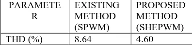
Fig.13 and Fig. 14 shows the FFT analysis using the two control techniques SPWM and SHEPWM. The Total Harmonic Distortion (THD) values are calculated and the results are compared as shown in the Table 1. Simulation results are presented to demonstrate the validity of selective harmonic elimination PWM technique.
PARAMETE R
EXISTING METHOD (SPWM)
PROPOSED METHOD (SHEPWM)
THD (%) 8.64 4.60
Table. 1 Comparison of %THD results
VII. CONCLUSION
In this paper voltage sag compensation using dynamic voltage restorer was considered. A Butterworth passive LC filter based strategy to control a DWT-operated DVR system has been developed and tested for power quality. The proposed passive filter based strategy has been used to approximate the DWT associated digital filters based one in controlling DVR input and output voltages. Butterworth passive LC filters have shown the ability to reduce the delay in the overall DVR system response. A DWT-operated DVR system has been used to compensate load side voltage to improve the power quality under any abnormal condition. Two pulse width modulation-based control techniques, viz sinusoidal PWM and selective harmonic elimination PWM, have been implemented for controlling the switching operation of the inverter used in the DVR system. The control techniques were tested and the reliability and effectiveness of control schemes are shown in results. It is observed that selective harmonic elimination PWM utilized the better dc voltage and reduced the harmonic distortion in phase voltage when compared with sinusoidal PWM and it effectively mitigated the voltage sags. Compared with sinusoidal PWM. The proposed approach was expected to show efficient, effective, and quick responses to improve the power quality under different abnormal operating conditions.
REFERENCES
[1] Mahesh Singh and VaibhavTiwari, “Modelling analysis and solution of power quality problems,” International Journal of Computer and Electrical Engineering.
[2] Rosli Omar, Nasrudin Abd Rahim and Marizan Sulaiman, “Modelling and simulation for voltage sags/swells mitigation using Dynamic Voltage Restorer (DVR),” Journal of Theoretical and Applied Information Technology, pp.464-470, 2009.
[3] Sunil Kumar Gupta, H. P. Tiwari and Rames Pachar, “Study of Major Issues and their Impact on DVR system performance,” International Journal of Computer and Electrical Engineering. Vol. 2, No.1, February 2010.
[4] S.V. Ravi Kumar and S.SivaNagaraju, “Simulation of D-STATCOM and DVR in Power Systems,” ARPN Journal of Engineering and Applied Sciences, Vol. 2, No.3, June 2007.
[5] C.K. Chui, “ Wavelets: A Mathemetical Tool for Signal Processing ,” ser. Soc. Ind. Appl. Math. Philadelphia, PA: SIAM, 1997.
[7] E. W. Gunther and H. Mehta, “A Survey of distribution system power quality,” IEEE Trans. Power Del, Vol.10, No.1, pp. 322-329, Jan.1995.
[8] F. Mohammed , Mahdianpoor and Rahmat Allah Hooshmand, “A New Approach to Multifunctional Dynamic Voltage Restorer Implementation for Emergency Control in Distribution System,” IEEE trans. Power Delivery , Vol.26, No2, Apr 2011.
[9] I.W. Selesnick and C. S. Burrus, “Generalized Digital Butterworth Filter Design,” IEEE Trans. Signal process.,Vol.46, No 6, pp. 1688-1694, Jun 1998.
[10] M. Sifuzzaman, M.R. Islam and M.Z. Ali, “Application of Wavelet Transform and its Advantages Compared to Fourier Transform,” Journal of Physical Sciences, Vol. 13, 2009.
[11] M. Vetterli and C. Herley, “Wavelets and Filter Banks: Theory and Design,” IEEE Trans. signal process, Vol.40, No. 9.pp.2207-2232.Sep.1992.
[12] S.G.Mallat, “A Theory for Multi Resolution Signal Decomposition: The Wavelet Representation,” IEEE Trans. Pattern Anal. Mach. Intell., Vol.11, No.7, pp. 671-693, Jun.1989.
[13] SNV Ganesh, Dr. k. Ramesh Reddy and Dr. B. V. Sanker Ram, “Different Control Strategies for Power Quality Improvement Using Dynamic Voltage Restorer,” IEEE Students Technology Symposium 14-16 Jan. 2011.