International Journal of Engineering Trends and Technology (IJETT) - Volume4Issue5- May 2013
ISSN: 2231-5381
http://www.ijettjournal.org
Page 1491Cascaded Multilevel Inverter with
PWM Control Method
M.Kiran Kumar #1 , M.Saikiran *2 , Ch.Venkateswarlu #3
^1 Assistant Professor, Dept. of EEE, KL University, Vaddeswaram, AP, India.
#2 Final Year B. Tech, Dept. of EEE, KL University, Vaddeswaram, AP, India.
#3 Final Year B. Tech, Dept. of EEE, KL University, Vaddeswaram, AP, India.
Address
Abstract—A hybrid cascaded multilevel inverter with PWM method is presented in this paper. It consists of a standard 3-leg inverter (one leg for each phase) and H-bridge in series with each inverter leg. It can use only a single DC power source to supply a standard 3-leg inverter along with three full H-bridges supplied by capacitors. Multilevel carrier- based PWM method is used to produce a five-level phase voltage. The inverter can be used in hybrid electric vehicles (HEV) and electric vehicles (EV). A simulation model based on PSIM and MATLAB/SIMULINK is developed. An experimental 5 kW prototype inverter is built and tested. The results experimentally validate the proposed PWM hybrid cascaded multilevel inverter.
I. INTRODUCTION
The multilevel inverter has gained much attention in recent years due to its advantages in high power with low harmonics applications. The general function of the multilevel inverter is to synthesize a desired high voltage from several levels of dc voltages that can be batteries, fuel cells, etc.
In this paper, the proposed hybrid cascaded multilevel inverter includes a standard 3-leg inverter (one leg for each phase) and H-bridge in series with each inverter leg. It can use only a single DC power source to supply a standard 3-leg inverter along with three full H-bridges supplied by capacitors. Traditionally, each H-bridge requires a DC power source [1-5]. Multilevel carrier- based PWM method is used to produce a five level phase voltage.
The inverter can be used in hybrid electric vehicles (HEV) and electric vehicles (EV). An HEV combines a conventional internal combustion engine, a battery pack, and an electric motor. An EV includes rechargeable batteries and an electric motor. The power inverter that drives the electric motor is a key device of a HEV and EV.
To develop the model of a hybrid multilevel inverter, a
simulation is done based on PSIM and MATLAB/SIMULINK platforms. Their in t egr ati on makes th e design an d analysis o f a hybrid multilevel inverter more complete and detailed [6]. A 5 kW prototype has experimentally validated the proposed PWM hybrid cascaded multilevel inverter.
Fig 1. Topology of HYBRID CASCADED MULTILEVEL INVERTER
International Journal of Engineering Trends and Technology (IJETT) - Volume4Issue5- May 2013
ISSN: 2231-5381
http://www.ijettjournal.org
Page 1492II. OPERATION PRINCIPLE OF THE HYBRID MULTILEVEL
INVERTER
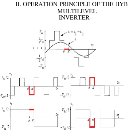
Fig. 3. Capacitor voltage regulation process.
standard 3-leg inverter with a DC power source. The top is an H-bridge in series with each standard inverter leg. The H-bridge can use a separate DC power source or a capacitor as the dc power source [7-11].
The output voltage v1 of this leg (with respect to the ground) is either +Vdc/2 (S5 closed) or Vdc/2 (S6 closed). This leg is connected in series with a full H-bridge that in turn is supplied by a capacitor voltage. If the capacitor is kept charged to Vdc/2, then the output voltage of the H- bridge can take on the values +Vdc/2 (S1, S4 closed), 0 (S1, S2 closed or S3, S4 closed), or
Vdc/2 (S2, S3 closed). An example output waveform that this topology can achieve is shown in Fig. 3 (a). When the output voltage v = v1 + v2 is required to be zero, one can either set v1 = +Vdc/2 and v2 = Vdc/2 or v1 = Vdc/2 and v2 = +Vdc/2. It is this flexibility in choosing how to make that output voltage zero that is exploited to regulate the capacitor voltage.
When only a dc power source is used in the inverter, that is, the H-bridge uses a capacitor as the dc power source, the capacitor’s voltage regulation control details are illustrated in Fig. 3. During 1 ! ! ", the output voltage in Fig. 2 is zero and the current i > 0. If S1, S4 are closed (so that v2 = +Vdc/2) along with S6 closed (so that v1 = Vdc/2), then the capacitor is discharging (ic =
i < 0
As Fig. 3 illustrates, this method of regulating the capacitor voltage depends on the voltage and current not being in phase. That means one needs positive (or negative) current when the voltage is passing through zero in order to charge or discharge the capacitor. Consequently, the amount of capacitor voltage the scheme can regulate depends on the phase angle difference of output voltage and current. It is noted that the above capacitor voltage regulation method is described using a fundamental frequency modulation scheme because it is easier to illustrate [7]. The PWM scheme uses the same method as described in the next section.
III. PSIM AND SIMULINK CO-SIMULATION
International Journal of Engineering Trends and Technology (IJETT) - Volume4Issue5- May 2013
ISSN: 2231-5381
http://www.ijettjournal.org
Page 1493frequency switching methods can be used for the hybrid multilevel inverter. Multilevel carrier based PWM strategies are the most popular methods because they are easily implemented. Three major carrier-based techniques that are used in a conventional inverter can be applied in a multilevel inverter: sinusoidal PWM (SPWM), third harmonic injection PWM (THPWM), and space vector PWM (SVM). SPWM is a popular method in industrial applications. It uses several triangle carrier signals, one carrier for each level and one reference, or modulation, signal per phase. In the proposed inverter, the top H-bridge inverter is operated under the SPWM mode and the bottom standard 3-leg inverter is operated under square-wave mode in order to reduce switching loss. For an m-level inverter, the amplitude modulation index, ma, is defined as
,where, Am is the peak-to-peak reference waveform amplitude, Ac is the peak-to-peak carrier waveform amplitude.
Fig. 5. H-bridge (top) and standard inverter (bottom) output voltage
International Journal of Engineering Trends and Technology (IJETT) - Volume4Issue5- May 2013
ISSN: 2231-5381
http://www.ijettjournal.org
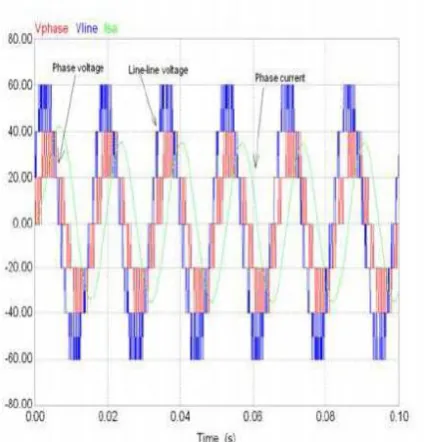
Page 1494In this paper, the simulation model is developed with PSIM and MATALB/SIMULINK. The PSIM model for the power circuit is shown in Fig. 4. Its control functions are completed in MATLAB/SIMULINK. One can therefore make full use of PSIM’s capability in power simulation and MATLAB/SIMULINK’s capability in control simulation in a complementary way. A key issue to realize the control method is that the capacitors voltages (Vc) need to be kept regulated to one half of the DC voltage (Vdc/2). To regulate a capacitor’s
voltage, if i > 0 and Vc < Vdc/2, the inverter controls the bottom inverter to output Vdc/2 and the top H-bridge to output Vdc/2 for inverter’s 0 voltage output; if i > 0 and Vc > Vdc/2, the inverter controls the bottom inverter to output Vdc/2 and the top H-bridge to output Vdc/2 for inverter’s 0 voltage output. The i < 0 situation is similar to the i > 0 situation, the controller just needs to reverse its switching signals. The top H-bridge and bottom standard 3-leg inverter output voltage waveform are shown in Fig. 5. Fig. 6 shows the simulation results, which include phase voltage, line-line voltage, and phase current. The output phase voltage is five-level and the output phase current is sinusoidal. Moreover, the PWM scheme makes the inverter output zero voltage for significant time intervals so that the capacitor can be charged or discharged during these periods.
IV. EXPERIMENT VERIFICATION
A 5 kW prototype using power MOSFETs (100V,180A) as shown in Fig. 7 has been built in order to verify the proposed hybrid multilevel inverter. The load is a 15 hp three-phase induction motor, which is loaded less than 5 kW. An Alter FLEX 10K field programmable gate array (FPGA) controller is used to implement the control algorithm to drive the motor with the real-time variable output voltage and variable frequency. The FPGA controller is designed as a card to be plugged into a personal computer, which uses a peripheral component interconnect (PCI) bus to communicate with the microcomputer in which a Visual Basic interface is used to input and adjust the control schemes and parameters.
Fig. 7. 5 kW Hybrid cascaded multilevel inverter prototype
Fig. 8. FPGA controller block diagram.
International Journal of Engineering Trends and Technology (IJETT) - Volume4Issue5- May 2013
ISSN: 2231-5381
http://www.ijettjournal.org
Page 1495Switching signal data are stored in a 12×1024 bits in- chip RAM. An oscillator generates a fixed frequency clock signal, and a divider is used to generate the specified control clock signal corresponding to the converter output frequency. Three phase address generators share a public switching data RAM because they have the same switching data with only a different phase angle. (The switching d a t a is only for one half cycles because the switching data is symmetric.) For each step, the three-phase signal controller controls the address selector to fetch the corresponding s w i t c h i n g data from the RAM to the output buffer according to the capacitor’s voltage.
Fig. 9. Output line-line and phase voltage, phase current of the hybrid cascaded multilevel inverter (ma=0.8).
Fig. 10. Normalized FFT analysis of phase voltage
.
Fig. 11. Normalized FFT analysis of phase current
The experimental results including phase voltage, line- line voltage, and phase current are shown in Fig. 9. DC bus voltage is 40V. The capacitor voltage is kept regulated to one half of the DC bus voltage. The output phase voltage is five-level. The phase current waveform is close to sinusoidal. Fig. 10 and Fig. 11 show the normalized FFT analysis results of phase voltage and phase current.
V. CONCLUSION
International Journal of Engineering Trends and Technology (IJETT) - Volume4Issue5- May 2013
ISSN: 2231-5381
http://www.ijettjournal.org
Page 1496REFERENCES
[1] L. M. Tolbert, F. Z. Peng, T. G. Habetler, “Multilevel converters for large electric drives,” IEEE Transactions on Industry Applications, vol. 35, no. 1, Jan./Feb. 1999, pp. 36-44.
[2] J. S. Lai and F. Z. Peng, “Multilevel converters – A new breed of power converters,” IEEE Transactions on Industry Applications,
vol. 32, no.3, May. /June 1996, pp. 509-517.
[3] J. Rodríguez, J. Lai, and F. Peng, “Multilevel inverters: a survey of topologies, controls and applications,” IEEE Transactions on Industry Applications, vol. 49, no. 4, Aug. 2002, pp. 724-738. [4] S. Khomfoi, L. M. Tolbert, “Multilevel power converters,” Power Electronics Handbook, 2nd Edition Elsevier, 2007, ISBN 978-0-12- 088479-7, Chapter 17, pp. 451-482.
[5] J. Liao, K. Corzine, M. Ferdowsi, “A new control method for single-DC-source cascaded H-Bridge multilevel converters using phase-shift modulation,” IEEE Applied Power Electronics Conference [6] Y. Zhang, Z. Zhao, H. Bai, L. Yuan, H. Zhang, “PSIM and
SIMULINK co-simulation for three-level adjustable speed drive systems” IEEE Power Electronics and Motion Control Conference, vol. 1, Aug. 2006, pp.1 – 5
[7] J. N. Chiasson, B. Özpineci, Z. Du, and L. M. Tolbert, “A five-level three-phase hybrid cascade multilevel inverter using a single DC source for a PM synchronous motor drive,” IEEE Applied Power Electronics Conference, February 25 - March 1, 2007, pp. 1504- 1507.
[8] Z. Du, B. Ozpineci, L. M. Tolbert, J. N. Chiasson, “Inductorless DC-AC cascaded H-Bridge multilevel boost inverter for electric/hybrid electric vehicle applications,” IEEE Industry Applications Society Annual Meeting, Sept. 2007, pp. 603-608.
BIOGRAPHIES
Malligunta Kiran Kumar received B.Tech Degree in Electrical and Electronics Engineering from Gokula Krishna College of Engineering and Technology J N T University,Hyderabad, India, in 2007.,M.E. Degree in Power Electronics and Drives from Sree Sastha Institute of Engineering and Technology, Anna University, Chennai, India, in 2010 and Pursuing Ph.D in Electrical Engineering at K L University, Guntur, India. Currently he is Asst. Professor in Electrical and Electronics Engineering, at K L University, Guntur, India. His research interest includes Switched Reluctance Machines, Power Electronics and Control Systems.
Email Id: [email protected]
Myneni Saikiran was born in India in 1992. He is pursuing B. Tech final year in KL University in Electrical and Electronics Engineering. His field of interest is in Electrical Machines and Power Electronics.
Email Id: [email protected]
Chaluvadi Venkateswarlu was born in India in 1991. He is pursuing B. Tech final year in KL University in Electrical and Electronics
Engineering. He is especially interested in the Power Electronics and Electrical Machines