GLOBAL JOURNAL OF ADVANCED ENGINEERING TECHNOLOGIES AND
SCIENCES
EFFICIENCY THRESHOLD CRITERION IN COUPLING FORKED MOVING
CONTACTS CIRCUIT BREAKERS AND CURRENT LIMITING REACTORS
1
Akpeh V.A,
2Ezechukwu O.A
1
Transmission Company of Nigeria (TCN)
2
Department of Electrical Engineering, Nnamdi Azikiwe University, Awka
ABSTRACT
This paper establishes the efficiency threshold criterion for the use of forked moving contacts on power circuit breakers (CBs) to enhance parallel operation of circuit breaker/current limiting reactor that approximates series short-circuit current limiting reactor connection with no constant power losses [1, 2]. It provides adequate guide for selecting appropriate Current Limiting Reactor (CLR) inductance (reactance) for an efficient power circuit breaker operating mechanism energy requirement and cost.
KEYWORDS: Circuit breaker, Criterion, Current Limiting Reactor, Efficiency, Forked moving contact, Inductance, Operating mechanism energy, Parallel operation, Reactance, Straight moving contact, Threshold.
INTRODUCTION
The use of forked moving contacts in circuit breakers gives CB/CLR connection arrangement that approximates a series short-circuit CLR connection that removes constant power losses in power systems [3]. In forked moving contact implementation meant for parallel operation of CB/CLR [4, 5, 6], there is an increased overall length of contact and reduced cross-sectional area. The meaning of this is that as the short-circuit current is reduced downwards; there is an initial increase in the mass of the forked moving contact up to a certain point after which the mass starts decreasing.
The short-circuit level below which the mass of the forked moving contact of a CB begins to reduce when compared with the mass of a straight moving contact of another CB on the same system without any short-circuit current limiting reactor, is very important in determining the operating mechanism energy requirement reduction and cost reduction for forked moving contact power circuit breakers. This point at which the short-circuit current must be reduced to; below which a reduced mass of forked moving contact when compared with that for the straight moving contact is obtained, is the efficiency threshold.
EFFECTS OF RATED SHORT-CIRCUIT BREAKING CURRENTS ON THE OPERATING
MECHANISM ENERGY REQUIREMENTS OF A POWER CIRCUIT BREAKER
RATED SHORT-CIRCUIT BREAKING CURRENTS AND THE BLAST PRESSURE
The rated short-circuit breaking current i, exercises its influence on the required operating mechanism energy mainly through the blast pressure ∆P which is necessary to warrant reliable arc-quenching under short-line fault conditions. Experimental results show the relationship between the required blast pressure ∆P and the current
slope 𝑑𝑖 𝑑𝑡 as:
∆P ∝ [𝑑𝑖 𝑑𝑡]
a (1)
Where:
The constant ‘a’ assumes a value between 1.1 and 1.42, depending on the filling pressure Po in the circuit
breaker [7].
However, as already confirmed by many authors, blast pressure ∆P, can be reduced by increasing the number of breaks N. With the well known relationship between current slope 𝑑𝑖
𝑑𝑡 and the rate of rise of re-striking voltage (RRRV) 𝑑𝑣
𝑑𝑡 𝑑𝑣
𝑑𝑡 . [ 𝑑𝑖 𝑑𝑡]
n = constant (2)
With large varying values between 1 and 7 as is always the case, specified for n, the effect of N on ∆P can be obtained as follows:
The response curve arising from equation (4) is as shown in figure 1.
Figure 1: Response curve of blast pressure against fault current
RATED SHORT-CIRCUIT BREAKING CURRENTS AND THE MOVING CONTACT AREA
The rated short circuit breaking current also has effect in the required blast volume, or if the contact stroke is not modified, the piston area, A, will be influenced because the nozzle cross-section has to be adapted to the arc cross-section AA. As a first approximation, the following relationship can be assumed:
A ∝ AA ∝
𝑖
√P (5)
As the pressure P = P0 + ∆P depends again on the current, the dependence of the nozzle cross-section and the
Piston area on current is less than one would expect. For large blast pressure, ∆P is much greater than P0, i.e.
∆P >> P0
And thus,
P ≈ ∆P Where
P = pressure A = piston area ∆P = blast pressure P0 = filling pressure
AA = arc cross-section
Substituting equation (4) in (5) gives A ∝ 𝑖
√(𝑖1.4.𝑁−0.28)
This implies
A ∝ 𝑖
𝑖0.7.𝑁−0.14
i.e.
A ∝ i x i-0.7 x N0.14
Or
A ∝ i0.3 x N0.14 (6)
The response curve arising from equation (6) is shown in figure 2.
100 150 200 250 300 350 400 450 500 550 20
30 40 50 60 70 80 90 100
BLAST PRESSURE [kg/cm2]
F
a
u
lt
c
u
rr
e
n
t
[k
A
Figure 2: Response curve of the moving contact area against the fault current
THE BLAST PRESSURE AND THE COMPRESSION WORK
The relationship between blast pressure ∆P and compression work, Wcomp, is not simple since one part of the
blast pressure is produced by the arc through heating up. Assuming a linear relationship as a rough approximation [7], ∆P relates with the compression work, WCOMP thus:
WCOMP ∝ N.A. ∆P (7)
But
√𝑃 ∝ 𝑖 𝐴 And
P = P0 + ∆P (8)
But for large blast pressure: ∆P ≫ P0 and so P ≈ ∆P.
From equation (6),
A ∝ i0.3.N0.14
Substituting equations (4) and (6) in equation (7) gives
WCOMP ∝ N.i0.3.N0.14.i1.4.N-0.28
OR
WCOMP ∝ N0.86.i1.7 (9)
The response curve of equation (9) is shown in figure 3.
Figure 3: Response curve of compression work against fault current
THE MOVING CONTACT MASS
The mass of the copper moving contact, M, is the product of its volume, V, and the density, d. i.e.
3 3.5 4 4.5
30 40 50 60 70 80 90 100
AREA[cm2]
F
a
u
lt
c
u
rr
e
n
t[
k
A
]
0.5 1 1.5 2 2.5 3 3.5 4 4.5
30 40 50 60 70 80 90 100
COMPRESSION WORK[kilo Newtons]
F
a
u
lt
c
u
rr
e
n
t[
k
A
Where
h = the height (i.e. the length) of the moving contact and A = the cross sectional area of the moving contact. But from equation (6), A ∝ i0.3 x N0.14 Such that:
M = d x h x i0.3 x N0.14 (10)
The effect of the increased overall length (height) of the forked moving contact rod on its mass [2], is shown in the response curves given in figure 4, while some selected fault levels and the corresponding effect of the increased overall length (height) of the forked moving contact rod on its mass is given in tables 1.
Figure 4: Response curves of the overall mass of the straight and the forked moving contact against the fault current.
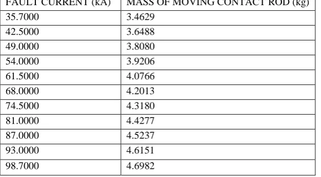
Table 1a: Fault current and the corresponding mass of moving contact rod (straight rod of 120cm length)
FAULT CURRENT (kA) MASS OF MOVING CONTACT ROD (kg)
35.7000 3.4629
42.5000 3.6488
49.0000 3.8080 54.0000 3.9206
61.5000 4.0766
68.0000 4.2013
74.5000 4.3180 81.0000 4.4277
87.0000 4.5237
93.0000 4.6151
98.7000 4.6982
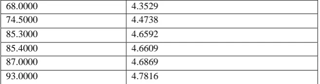
Table 1b: Fault current and the corresponding mass of moving contact rod (forked rod of 124.33cm overall length)
FAULT CURRENT (kA) MASS OF MOVING CONTACT ROD (kg) 35.7000 3.5878
42.5000 3.7805 49.0000 3.9454 54.0000 4.0621
61.5000 4.2237
3400 3600 3800 4000 4200 4400 4600 4800 30
40 50 60 70 80 90 100 110 120
MASS[kg]
F
a
u
lt
c
u
rr
e
n
t[
k
A
]
NO CLR used on straight moving contact
68.0000 4.3529 74.5000 4.4738
85.3000 4.6592
85.4000 4.6609
87.0000 4.6869
93.0000 4.7816
CURRENT REDUCTION AND THE FORKED MOVING CONTACT MASS
When the moving contact is forked, the overall length (height) is slightly increased. From the expression: Mass = volume (i.e. area x height) x density, it appears there could be increased mass and as such increased operating mechanism energy but as shown in equations (6), (7) and (9), reducing the current reduces the cross-sectional area of the moving contact rod and the compression work, ‘WCOMP’. That is, the mass of the moving contact rod
is reduced even though the height is slightly increased as can be seen in the response curve of the moving contact area against the fault current, for the values of ‘I’ between 35.7kA and 98.7kA and for number of breaks, ‘N’ = 2, shown in figure 2.
This is clearly seen in the response curve of fault current reduction against the overall mass of the forked moving contact rod of the CB (overall length = 124.33cm) [2], compared with the mass of the required (straight) moving contact rod (length = 120cm) when no CLR is used, shown in figure 4. However, it should be noted from figure 4 that the fault current must be reduced below a certain limit (the efficiency threshold) before the mass of the rod begins to decrease else, the mass is higher.
DISCUSIONS
As shown with the aid of equation (10), in table 2, which resulted to table 3, it can for instance be seen that, limiting the fault current from 98.7kA to 87.8kA shows an increase in the mass of the rod (i.e. above 4.6982kg value gotten at 98.7kA for a straight moving contact rod), but reducing 98.7kA below 87.8kA yields the desired result. The efficiency threshold for this case is therefore 87.7kA.
Table 2a: Fault current and corresponding cross-sectional area, volume, and mass of the straight moving contact rod of length = 120cm.
FAULT
CURRENT (kA)
CROSSECTIONAL AREA OF MOVING CONTACT ROD (cm2)
VOLUME OF
MOVING CONTACT ROD (cm3)
MASS OF MOVING CONTACT ROD (kg)
98.7 4.3696 524.3492 4.6982
93.0000 4.2923 515.0748 4.6151
87.0000 4.2073 504.8719 4.5237 85.3000 4.1824 501.8919 4.4970 68.0000 3.9075 468.8977 4.2013 61.5000 3.7915 454.9755 4.0766 54.0000 3.6464 437.5660 3.9206 49.0000 3.5416 424.9954 3.8080 42.5000 3.3936 407.2322 3.6488 35.7000 3.2207 386.4790 3.4629
Table 2b: Fault current and corresponding cross-sectional area, volume, and mass of the forked moving contact rod of overall length = 124.33cm.
FAULT
CURRENT (kA)
CROSSECTIONAL AREA OF MOVING CONTACT ROD (cm2)
VOLUME OF MOVING CONTACT ROD (cm3)
MASS OF MOVING CONTACT ROD (kg)
98.7000 4.3696 543.2694 4.8677
93.0000 4.2923 533.6604 4.7816
87.7000 4.2174 524.3485 4.6982
87.6000 4.2159 524.1690 4.6966
87.0000 4.2073 523.0894 4.6869
68.0000 3.9075 485.8171 4.3529
61.5000 3.7915 471.3925 4.2237
Table 3a: The effect of the use of CLR on the overall mass of the forked CB moving contact rod.
Fault current (kA) with no CLR
Mass of straight moving contact rod (kg) with no CLR used
98.7kA limited downwards with CLR
Corresponding mass of forked moving contact rod (kg) with CLR used
98.7000 4.6982
93.0000 4.7816
87.7000 4.6982
87.6000 4.6966 87.0000 4.6869 68.0000 3.2910 61.5000 3.1933 54.0000 3.0711 49.0000 2.9829 42.5000 2.8582 35.7000 2.7126
Table 3b: The effect of the use of CLR on the overall mass of the forked CB moving contact rod.
Fault current (kA) with no CLR
Mass of straight moving contact rod (kg) with no CLR used
93kA limited downwards with CLR
Corresponding mass of forked moving contact rod (kg) with CLR used
93.0000 4.6151
88.0000 4.7030 85.0000 4.6543
82.6400 4.6151
68.0000 4.3529
61.5000 4.2237 54.0000 4.0621 49.0000 3.9454 42.5000 3.7805
Table 3c: The effect of the use of CLR on the overall mass of the forked CB moving contact rod.
Fault current (kA) with no CLR
Mass of straight moving contact rod (kg) with no CLR used
87kA limited downwards with CLR
Corresponding mass of forked moving contact rod (kg) with CLR used
87.0000 4.5237
85.0000 4.6543
77.3050 4.5237
68.0000 4.3529
61.5000 4.2237 54.0000 4.0621 49.0000 3.9454
Table 3d: The effect of the use of CLR on the overall mass of the forked CB moving contact rod.
Fault current (kA) with no CLR
Mass of straight moving contact rod (kg) with no CLR used
68kA limited downwards with CLR
Corresponding mass of forked moving contact rod (kg) with CLR used
68.0000 4.2013
64.0000 4.2745
60.4200 4.2013
Table 3e: The effect of the use of CLR on the overall mass of the forked CB moving contact rod.
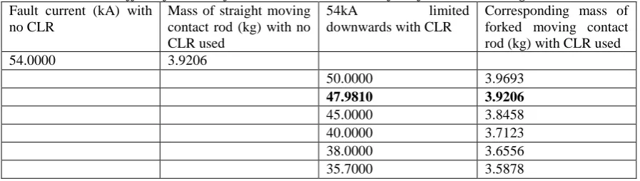
Fault current (kA) with no CLR
Mass of straight moving contact rod (kg) with no CLR used
54kA limited downwards with CLR
Corresponding mass of forked moving contact rod (kg) with CLR used
54.0000 3.9206
50.0000 3.9693
47.9810 3.9206
45.0000 3.8458 40.0000 3.7123 38.0000 3.6556 35.7000 3.5878
In all the cases examined above, it is observed that as short-circuit current limiting reactor is used on the forked moving contact circuit breaker to reduce the short-circuit level, the mass of the forked moving contact when compared to that for the straight moving contact used in the same system with no current limiting reactor, increases to a point and then starts decreasing as shown in figure 4 and tables 3a to 3e. The current below which the mass of the forked moving contact begins to reduce is the efficiency threshold for the forked moving contact CB.
The Current limiting reactor is not arbitrarily chosen for any particular system under study. There is the efficiency limit consideration. The efficiency limit of the current limiting reactor is the effective value of the impedance (reactance) required for the system under study [8]. The efficiency threshold is therefore very necessary in determining the impedance value of the Current limiting reactor needed to limit the anticipated short-circuit level in a given power system for an efficient power circuit breaker operating mechanism energy requirement and cost.
CONCLUSIONS
This paper has presented an efficiency threshold criterion which is very necessary in determining the optimum operating mechanism energy requirement and cost for a forked moving contact power circuit breaker. The implication of this is that the series short-circuit current limiting reactors to be used in conjunction with the forked moving contact power circuit breakers are not arbitrarily chosen without due consideration to this efficiency threshold criterion to ensure minimal power circuit breaker operating mechanism energy requirement as well as cost minimization.
REFERENCES
[1] Akpeh, V.A., Madueme, T.C. and Ezechukwu, O.A. (2015). A new approach to Implementing Fault Current Limiting Reactors (CLRs) on Feeders with Negligible Constant Power losses. India: International Journal of Modern Engineering Research. 5, (11), 37-46.
[2] Akpeh, V.A. and Echedom, V.C. (2017). Forked Moving Contacts in Power Circuit Breakers: Solution to Constant Power Losses Incurred in the Use of Series Shot-circuit Current Limiting Reactors on Feeders. Global Journal of Advanced Engineering Technologies and Science 4, (4) 1-15.
[3] Akpeh V.A., Madueme T.C., Ezechukwu O.A., Ogboh V.C., Echedom V.C. (2015). A Methodology for Implementing Fault Current Limiting Reactors (CLRs) on Feeders with Minimal Constant Power Losses. Global Journal of Engineering, Design & Technology, 4, (5), 1-7.
[4] Brandt, A., Hartung, K.H., Bockholt, R. and Schmidt, V. (2010). IS – limiter: Limitation of Shortcircuit Currents for maximum economic benefits. ABB AG - 40472 Ratingen (Germany), pp. 1-4.
[5] Akpeh, V.A. and Omini, G.U. (2017). Improved Is – Limiter Technique for Implementing Fault
Current Limiting Reactors on Feeders at no Constant Power Losses. India:International Journal of Engineering Sciences & Research Technology 6, (4), 273- 276.
[6] Hartung, K.H. (2002). Is-Limiter, the Solution for High Short-Circuit Current Applications. ABB Calor Emag. 12-18.
[7] Bachofen, F., Steinegger, P. and Glauser, R. (1982). A Novel Solution for High Speed SF6 Puffer Type
Power Circuit Breakers of High Rated Capability with Low Operating Mechanism Energy. Paris: International Conference on Large High Voltage Electric Systems. Cigre WG 13-07. 1-8.