STUDY OF THIN WALLED CONE BY USING OF
FINITE ELEMENT ANALYSIS IN DEEP DRAWING
Dr. Shailendra Dwivedi
1, Dr. Anil Singh Yadav
2, Pushkal Badoniya
31
Department of Mechanical Engineering, Lakshmi Narain College of Technology, Bhopal (India)
2,3
Department of Mechanical Engineering, Lakshmi Narain College of Technology Excellence,
Bhopal (India)
ABSTRACT
In this research paper the study has been carried on proposes modeling of deep drawing tool geometry for thin
sheet metal. Steel grade TS230 material has been taken and cone thickness (thin walled 0.155 mm) has been
considered. Tooling with influential parameters is modelled and analyzed with ABAQUS 6.10 software haven
been used for analysis. Minimum drawing force necessary for selected tool geometry and overall tool behavior
is investigated during study. Heat generation of selected tooling of deep draw process and its influence on thin
sheet metal deformation is also being considered. Optimization of process is achieved by elimination of errors
that appear in form of wrinkling, excessive thinning or fracture.
I. INTRODUCTION
Deep drawing process is constantly subjected to sheet metal forming process. In this research paper in order to
achieve higher efficiency and reduce the production cost of deep drawing process of thin walled tinplate is
evaluated. The evaluation of deep drawing process is regarding mechanical properties and consists of achieving
minimal process force, determination of optimal blank shape, optimization of forming steps, product stability,
and minimal thickness in product, wrinkling, spring back and prediction of defects. Changes in material
properties reflect to the final product geometry, in this study it is assume that the same tooling geometry and
work conditions are used. Defects that occur in deep drawing process can be considered and their causes have
been analyzed. The process requires deep understanding of thin walled tinplate products production and deep
drawing process. The state of stress and their component and strain and their component flow in the product
requires is determined by tool radii, material properties, temperature generated in process etc. and these cause of
wrinkling, tearing and reduced formability [1,7].
II. MATERIAL
Thin walled plate, electrolytic tinplate is a cold rolled low carbon mild steel sheet or coil coated on both surface
with in layer that is applied in continuous electrolytic operation. This can be applied equally or differentially
where one surface carries heavier tin coating than other. Tinplate is produced in sheets or strips of a thickness
from 0.100 to 0.49 mm, with carbon content up to 0.13 % C, table 1. Tinplate surface is therefore covered on
both sides with a thin layer of primer tin, minimum purity 99.85 %, this gives it the white color and thus it is
investigated. TS230 has non-ageing quality and is suitable for the fabrication of deep drawn products. Standard
ultimate tensile strength for material TS230 is Rm= 325 ± 50 MPa, while Rockwell hardness HR 30 Tm: 52.
Table 1: TS230 (1.0371) Material Composition % [3]
C Si Mn Ni P S Cr Mo N Al Cu As Sn
0.04-0.08 0.03
0.18-0.35
0.08 0.02 0.02 0.08 0.02 0.008 0.08 0.08 0.02 0.02
The flow curve of material can be described in the form of hardening law:
(1)
Where: is the true stress, is the true plastic strain, n is the strain-hardening exponent, C is the strength
coefficient. Experimental results of uniaxial tensile test in order to obtain C and n was conducted in angle of 0°,
45°and 90° in regards to rolling direction of sheet metal strip. The resulting flow curve that will be used in
simulation has a form of:
(2)
In this paper such tooling is investigated for material of thickness 0.155 mm. Thin sheet causes sudden
wrinkling and usual formula = (5 -10)· (where is die radius, sheet thickness) and = rd·(2-5) (where
is punch radius) don't work properly, the necessary radius are much bigger [5]. The process consists of two
steps and they have to be planed accordingly. Second tool in process must be made to take the work piece form
first step and execute finished product. The thin walled sheet metal blank has a single grain structure, so the
stresses can influence the final result of specified product design. In factory conditions typical working
temperature of thin walled products was measured to be around 35 °C. Therefore care of the grain orientation
and anisotropy must be minimized. Initial blank size used in investigation is 120 mm, finish product radius is
by equation (3) the ideal height .
(3)
The maximum drawing force can be calculated by equation (4):
(4)
where Fd,max- drawing force, - cup diameter, - sheet thickness, UTS - ultimate tensile strength, n -
drawing coefficient for metal (0.7 - 0.95). For material TS230 =0.95· π·120·0.155·395 = 21916 N.
Friction between material and die was tested [6] and for investigation in simulation penalty friction μ = 0.25 was
Fig. 2: Assembly of two step tooling setup in ABAQUS of Die and Cone
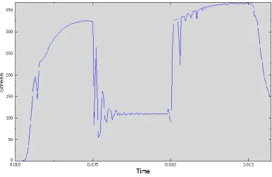
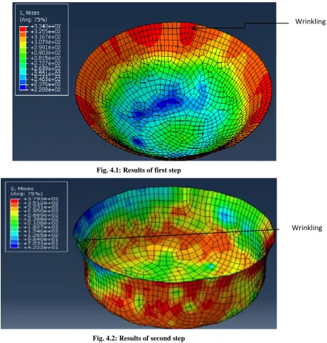
Results of first step is max Von Misses stress 334 MPa and depth of 25 mm, while second step approached max
limit with 380 MPa and obtained the target depth of 34 mm, figure 3 and 4. In first step the radii of punch and
die were changed until the wrinkling was eliminated final die radius was selected of rd= 38 mm was used in
combination with punch radius of rp= 20 mm. In second step problems occurred with connecting with first step,
rd= 18 mm and rp =14 mm was used. The die should come into effect immediately after the first step is
finished, however simulation showed most errors in connecting with second step. For second step final product
geometry was used, results showed small error in the form of wrinkling and earring in comparison to expected
behavior of material in work condition.
Fig. 4.1: Results of first step
Fig. 4.2: Results of second step
III. CONCLUSION
By simulation the necessary data needed for creation of optimized tooling design was obtained and critical
points have been analyzed. In first step die radius of rd= 38 mm was used in combination with punch radius of
rp= 20 mm in order to achieve depth of 25 mm, wrinkling was eliminated. In second step rd= 18 mm and rp
=14 mm was used in order to obtain final product geometry was used, results showed small error in the form of
wrinkling and earring in comparison to expected behavior of material in work condition. Tooling design for first
and second step was created with control of stress according to hardening law in order to eliminate fracture and
Wrinkling
REFERENCES
[1] B. Barisic, G. Cukor, L. Pletenac, Modeling and Simulation of Deep Drawing Tool Geometry,
Proceedings of the 15th InternationalDAAAM Symposium; BrankoKatalinicVienna, DAAAM
International Vienna, 2004. 29 - 30.
[2] Tinplate Euronorm EN10202eng, Cold Reduced Tinmill Products - Electrolytic Tinplate and Electrolytic
Chromium/Chromium Oxide Coated Steel, CEN - European Committee for Standardization Brussels
2001.
[3] Steel number and material composition, EN 10202: 2001 http://www.steelnumber.com, 2013.
[4] R. Coles, M. Kirwan, M. Edwards, N. May, 5. Metal Packaging, Published Online: 17 MAR 2011,
DOI:10.1002/9781444392180.ch5.
[5] M. Krsulja, Z. Car, H. Radelja, Behaviour of X5 CrNiMo 17-12-2 Material During Deep Drawing
Process., METALURGIJA, Vol. 51(2012) , 2-203-206.
[6] Krsulja, Marko, Roskanin, Petr; Kudlacek, Jan; Pomenic, Loreta, Car, Zlatan. Investigation of Coatings
Friction Coefficient Used in Production of Deep Drawn Packaging Cans, International Conference on
Innovative Technologies IN-TECH 2012, 443 – 446, 2012
[7] FlavioCimolin, Roberto Vadori and Claudio, “Springback compensation in deep drawing application”,