RESEARCH ARTICLE
Congestion Aware Packet Routing for Delay
Sensitive Cloud Communications
Vincent O. Nyangaresi
School of Informatics & Innovative Systems, Jaramogi Oginga Odinga University of Science & Technology, Kenya.
[email protected]
Silvance O. Abeka
School of Informatics & Innovative Systems, Jaramogi Oginga Odinga University of Science & Technology, Kenya.
[email protected]
Solomon. O. Ogara
School of Informatics & Innovative Systems, Jaramogi Oginga Odinga University of Science & Technology, Kenya.
[email protected]
Published online: 28 July 2017
Abstract – In the recent years, many organizations have turned to cloud technology to support their information technology services. The cloud servers are therefore increasingly holding huge and sensitive information belonging to diverse groups of individuals and companies. Additionally, some organizations employ the cloud to provide them with online backup services. One of the most outstanding requirements for cloud customers is availability – the customers must be able to access their information and other resources stored in the cloud any time and from anywhere on the globe. This means that there should be efficient network design such that any delays are averted. The connection between the customer and the cloud can therefore be regarded as delay senstive. Network congestions often lead to delays and packet losses. Transmission control protocol employs four congestion control algorithms – slow start, congestion avoidance, fast retransmit and fast recovery, all of which fail to meet the requirements of delay intolerance. Transmission control protocol pacing has been suggested as a possible solution to delays and packet dropping in computer networks. However, the conventional pacing is static in nature, meaning that constant pauses are introduced between packet transmissions to prevent bursty transmissions which can lead to delays at the receiver buffers. This paper therefore presents a congestion aware packet routing where the delay period is hinged on the prevailing network conditions. This dynamic pacing algorithm was designed and implemented in Spyder using Python programming language. It employed probe signals to gather network intelligence such as the applicable round trip times of the network. Thereafter, this network intelligence was employed to tailor the paces to these network conditions. The results obtained showed that this algorithm introduced longer paces when more packets are transmitted and shorter paces when few packets are transmitted. In so doing, this new algorithm gives enough time for large packets to be delivered and smaller paces when few packets are sent. The analysis was done in terms of bandwidth utilization efficiency, round trip times and congestion window size adjustments. The congestion window – time graphs and
throughput – time graphs showed that the developed dynamic pacing algorithm adjusted quickly to network congestions hence ensuring that the network is efficiently utilized by averting delays.
Index Terms – Cloud Computing, Congestion, Network Delays, Algorithm, TCP Pacing.
1. INTRODUCTION
Routing algorithms are important in cloud communications in the specification of procedures to be employed in the transfer a data packet from the source to the destination. As [1] explain, to make an accurate routing decision, the routing algorithm must choose some criteria for making routing decision. Some of such metrics include bandwidth, number of hop counts, and transmission power. In this paper, congestion, which is another critical metric influencing the routes that packets take, is investigated. In networks with redundant communication paths with varying levels of congestion, the packets should be made to utilize the least congested channel.
RESEARCH ARTICLE
are not sent in a burst. In [3] a quantitative evaluation of TCP pacing is provided. The output showed that pacing provides better fairness, throughput, and lower drop rates in some circumstances. However, the results also indicated that pacing has significantly worse throughput than regular TCP in other situations. This is because of its susceptibility to synchronized losses and its habit of delaying congestion signals. As such, mechanisms to eliminate these challenges are required. In cloud communications, the company’s telecommunications applications, switching and storage services are hosted by a third-party [4]. To access these resources, the organization uses the public Internet. In so doing, the cloud offers on-demand access to a shared pool of computing resources such as computer networks, servers, storage, applications and services. Due to the rapid uptake of this technology, many organizations have their data centers located in the cloud to facilitate real time sharing of these resources among departments and even stakeholders, who might be interested in company informational resources, such as suppliers and customer [5]. This means that there is always real time connections established between the company and its data center resources. Security and availability of the cloud resources then becomes important for the survival of the cloud-dependent organizations.
As a result of the huge uptake of the cloud technology, there exists an increasing demand for physical devices such as servers to support the increasing number of operations among the hosted customers. Virtualization comes handy by allowing one physical hardware such as a server to support multiple operating systems and hence users [6]. Additionally, cloud services support distributed processing which can be used to improve company efficiency [7]. Due to the real time communication required between customer premise equipment (CPE) and the cloud servers, delays in this setup will then translate to huge financial losses among many organizations that depend on the cloud services for their operations.
Congested networks often lead to packet loss and delays. As [8] point out, cloud can be employed to provide cross-enterprise biometric identification. Therefore, delays in the authentication process can effectively lock out cloud stakeholders, or cause inconveniences.Further [9] explains that organizations normally utilize hybrid cloud, which can be a combination of private, community or public, to enable the connection of collocations, managed and dedicated services with cloud resources. Once again, this requires faster communication among these hybrid models.
To avert delays and network congestions, congestion control algorithms have been devised to deal with congestion and packet losses. Some of these algorithms include slow start, congestion avoidance, and fast recovery and fast retransmit [10]. Due to the limitations of these algorithms such as the inefficient utilization of the available bandwidth and the
reliance on explicit receiver notifications to infer packet losses and control the transmission rate, researchers have come up with other techniques such as TCP pacing to try and reduce packet losses and congestions in networks.
In TCP connections, at the beginning of each round-trip time, TCP senders infuse bursts of packets into the network, which often stress the network queues. The effects are packet losses, reduction in throughput and increased latency. Since data centers are characterized by burst traffic and small buffer sizes, then such effects can be catastrophic. As such, TCP pacing serves to reduce the burstiness of TCP traffic and to alleviate data buffering in routers. However, there is no agreement among the researchers on the overall benefits of pacing. The model developed in [11] demonstrated that for a particular buffer size, as the number of concurrent flows is increased beyond a Point of Inflection (PoI), non-paced TCP outperforms paced TCP.
In delay tolerant networks (DTNs), it is not easy to preserve stability in end to end networks due to long communication delay and high mobility of network. In the Store and Carry mechanism employed for these networks, a node can receive and store the messages in the buffer and wait for the chance to send them. This therefore calls for the definition of a new reliable and efficient routing strategy. Hence, [12] proposed hybrid routing algorithm, Spray and Wait with EBR (S&W with EBR), which is a combination of both Encounter Based Routing (EBR) protocol and Spray and Wait Routing (S&W) protocol. The simulation results demonstrated that the proposed routing scheme achieved better performance in terms of Delivery Probability, Overhead Ratio, Dropping Packets and Goodput.
RESEARCH ARTICLE
2. RELATED WORK
Many researchers have devised techniques for eliminating or at least reducing packet losses occasioned by network congestions. In [14] an adaptive auto-tuning of TCP pacing that adjusts the pacing speed dynamically is suggested. It is based on the network situation that is complicated by static and manual techniques. To achieve this, two types of dynamic pacing (congestion window pacing, and estimated available bandwidth pacing) were introduced and merged with BIC TCP congestion control at the sender.
To prevent packet losses that lead to performance deterioration, burst transmission were suppressed, available bandwidth was estimated and the excess growth of the congestion window size was restricted. The results indicated that this approach improved the TCP performance in parallel TCP communication.
A simple technique that evades bursty transmissions has been suggested by [15]. Instead of utilizing timers, this technique employs acknowledgements the first connection receives to clock packet transmissions of the second connection over the course of the first RTT when the next connection joins the network. On the same breadth, acknowledgements of the first and second connections are utilized to clock packet transmissions of the third connection.
A study by [16] developed a Discrete Delay Function (DDF for establishing new intermediate node in wireless sensor networks (WSN), and then forwarding packets through this best intermediate node. In addition, a handshaking technique was utilized to determine the node for forwarding the packets, then broadcasting this node to the rest of the nodes. In so doing, other nodes do not have to redo this next node determination, thereby saving the other nodes’ power and energy. In the conventional WSN, energy is wasted in routing through the intermediate nodes and congestion (and hence delays) occurs during the routing process.
In their paper, [17] describes a performance problem in Data Transfer Nodes (DTNs) regarding a fast sender overwhelming a slow receiver. Consequently, packets get dropped, leading to poor performance. Moreover, slow firewalls, under-buffered switches, or other network devices that cannot handle high speed transmissions can also lead to packet losses, whose retransmissions can lead to time wastage. Therefore, [17] developed a simple tuning daemon at the sender that can identify flows during congestion, and then instructs the Linux kernel to adjust those flows to a rate that the network and receiver can handle.
The desire to have more bandwidth for data transmission led to the development of all-optical network core. However, owing to the intrinsic constraints of this optical technology, only routers with small packet buffers are viable for interconnections. The efficient operation of such small-buffer
networks can be assured by making traffic as less bursty as possible. In [18], a packet pacing mechanism is proposed that can smooth traffic bursts. The theoretical analysis showed that this scheme can provide an assurance that queue length of routers is BIBO stable.
In an effort to boost the web surfing speed and avert delays, Google has come up with a multiplexing protocol called Quic UDP Internet Connections (QUIC). It operates at the transport layer and runs over User Datagram Protocol (UDP and is optimized to be utilized for HTTP/2 connections [19]. Its goal is to trim down end-to-end latency and works best (compared to TCP) for slow connections with high latency.
A novel cooperative transmission control mechanism, referred to as TCP-polite rate control (TPRC), is proposed by [20]. This technique is hinged on cooperative determination of new congestion indicator as a substitute for drop ratio and round-trip time. Here, cooperative measurement is employed to identify congestion metric of network. Afterwards, this value is fed back to rate-based pacing mechanism. In so doing, the transmission rate is kept at the lower bound of available bandwidth. The output showed that TPRC scheme outperformed TCP and TCP-friendly rate control protocol in terms of fast-start, efficiency, and fairness.
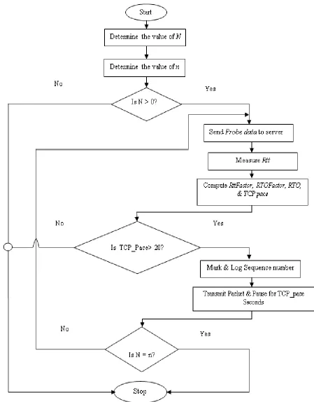
3. PROPOSED CONGESTION AWARE ALGORITHM An experimental research design using the simulation approach was adopted in this paper. The cloud communications were simulated by means of server virtualization, in which the Wamp server was employed to store the requested resources. The pseudo-code for the developed algorithm is illustrated in Algorithm 1. As the pseudo-code demonstrates, the first step was the starting of the algorithm after which the number of packets to be sent and the window size were determined. Provided that there were packets to be sent (N>0), then the probe signal was sent to the cloud server to measure the round trip time. However, if there were no packets o be transmitted to the receiver, the algorithm halted. After the probe signal was sent to the server, the duration it took the server to respond was measured, and from which the RttFactor was computed. The
RTOFactor, RTO and TCP_Pace were all calculated based on the sender’s own assessment of the network conditions. To prevent the network from entering into long delays, the TCP pace value was set to 20 seconds, which was a close approximation to the average duration the server’s responses took. In circumstances where the TCP paces went beyond this value, the corresponding packet was logged into a file for retransmissions.
RESEARCH ARTICLE
the other hand, if the congestion window was more than the number of packets sent so far, the algorithm shifted to step five, where probe signal were once again sent to the cloud server. The data flow diagram for this pseudo-code is shown in Figure 2. As this Figure 2 illustrates, there are three fundamental decisions to be made during the course of execution of this algorithm.
This involves whether the number of packets to be sent is depleted, whether the current TCP Pace exceeds the threshold of 20 seconds, and whether the number of packets sent so far is equal to the size of the congestion window.
The coding for this algorithm was accomplished in Spyder
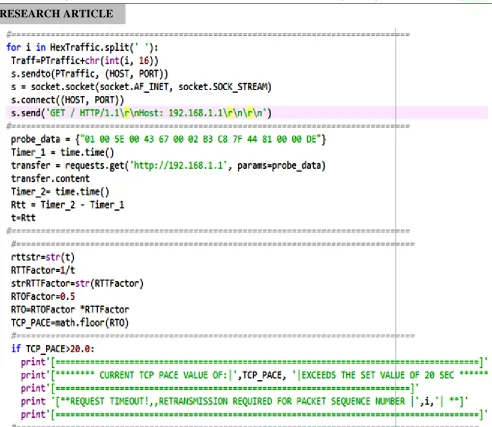
using Python programming language. Figure 3 gives the source code for the pseudo-code and data flow diagram discussed above.
Algorithm 1: Dynamic TCP Pacing Pseudo-Code The first line is the sequence of the probe data that were sent to
the server while the second line starts the sender retransmission timer. The third line sets the destination server IP address and specifies the data to be sent over. The fourth line transfers the packets while the fifth line stops the retransmission timer so that the elapsed time for the transmission process can be measured.
Moreover, the sixth line determines the value of Rtt as being the difference between the two sender retransmission timer values while the seventh line assigns this value to variable t. The eighth line serves to convert the measured Rtt into string for logging purposes. The ninth line establishes the RTTFactor
as being the inverse of the Rtt. The tenth line transforms the
RTTFactor to string for logging into text file. The eleventh line determines the RTOFactor to be 0.5, since the measured Rtt
was for half-duplex communication. The RTO is then the product of the RTOFactor and the RTTFactor as illustrated in line twelve.
The TCP pace on the other hand was obtained from the RTO
by taking the Python’s Math function floor of RTO. If the value of the computed TCP_Pace exceeded twenty (20) seconds, the packet was marked and logged for retransmission. However, if this value was less than twenty seconds, the TCP packets were sent with pauses equal to TCP_Pace between them. Since this TCP-Pace was computed for each data in the sliding window, dynamism in TCP paces was achieved.
Upon exceeding a TCP Pace of 20 seconds, the sequence number of the current packet is logged into a file for retransmissions as elaborated by the last line of Figure 3, where
RESEARCH ARTICLE
RESEARCH ARTICLE
Figure 3: Dynamic TCP Pacing Snippet 4. RESULTS AND DISCUSSIONS
Among the data collected in this study were received packets, current retransmission timeout (RTO), current round trip times (RTT), congestion window, throughput and TCP pace values. Figure 4 shows part of the results obtained. This figure shows that the received bytes from the cloud server were 189986 bytes while the current RTO value was 2.717391079 seconds. On the other hand, the current RTT value was 0.184000015259 seconds. The value of the congestion window at this RTT value was 189986 bytes, which corresponded with the size of the receiver buffer window size.
The throughput stood at 1484.265625 kilo bits per second transmission time while the value of the current TCP pacing was 2.0 seconds. To understand the implication of TCP pacing on congestion window and throughput, a comparison, a second
packet transmission scenario was considered, where the server was probed, packets sent and network measurements performed as illustrated in Figure 5. Here, the first line indicates the number of bytes the receiver has actually obtained from the server. The second line was that of the retransmission timeout as determined from the sender assessment. For Figure 5, when the value of the TCP pacing was 9 seconds, the values of the congestion window and throughput were 635592 and 4965.5625 bytes respectively.
RESEARCH ARTICLE
Figure 4: Results for TCP Pacing of Two Seconds
Figure 5: Results for TCP Pacing of Nine Seconds To establish the trend for the variation of the throughput and congestion window as TCP paces were varied, five observation instants were considered as demonstrated in Table 1. The values of network throughput and sender congestion window were observed as the values of the TCP paces were varied. The first column was for the calculated.
TCP pacing value while the second column was for the observed network throughput in kilo bits per second. The last column was that of the sender congestion window, measured in bytes.
As this table shows, for the third observation instant, the TCP pace value was 13.0 seconds and during which the throughput and congestion window were 7586.2578125 Kbps and 971041 bytes respectively. For the fourth observation instant, the TCP pace value was 15.0 seconds while throughput and congestion window were 8275.921875 Kbps and 1059318 bytes correspondingly. The last observation instant had a TCP pace value of 16.0 seconds, during which the values of throughput and congestion window were 8809.875 Kbps and 1127664 bytes respectively. To visualize the trend inferred herein, Figure 6 (a) and (b) were employed.
Table 1: Variations of Throughput and Congestion Window against TCP Paces
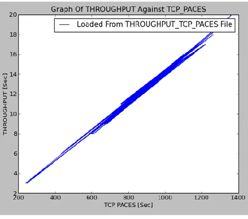
These figures assume almost the same shape, implying that TCP pacing affect congestion window and throughput in a similar version. The shape of both graphs is almost linear, which can be interpreted as follows: congestion window and throughput are directly proportional to the TCP Pacing value. This means that when high throughput is realized, the TCP paces are higher to allow the transmitted data to be received correctly. On the other hand, when fewer packets are sent, the TCP acing value is set to small values so that other packets are sent quickly over the same link and the network be probed again so that if conditions have improved, larger packets can be sent. This ensures efficient utilization of the communication link. These two graphs can be analyzed further to provide some predictive data for the congestion window size and throughput values. Figure 7 gives an illustration of how this prediction was achieved.
RESEARCH ARTICLE
(b)
Figure 6: TCP Pacing against Congestion Window and Throughput
Since this graph is a nearly a straight line graph, the relationship between throughput and the TCP paces can be expressed as shown in (1):
Throughput = [RF * TCP pace] (1) Where RF is the ramp factor.
The ramp factor for this graph was determined using (2): 𝛥 𝑌
𝛥𝑋 (2)
= 4
2000 (3)
This gives a value of 0.002 for the ramp factor. Therefore, at any observation instant, the relationship between throughput and the TCP paces is given by (4):
Throughput [Kbps] = 0.002 * TCP (4)
To validate this relationship, point R in Figure 5 was considered. At this instant, the TCP pace value was 2000. Therefore, according to (4), the throughput value should be equal to:
Throughput [Kbps] = 0.002 * 2000
(5)
This gives a value of 4 Kbps for the throughput, which a close approximation to the point where the straight line moving from point R cut the Y –axis, the throughput. Therefore (4) is valid. The implication is that TCP pace and the network throughputs were directly related. As such, during the periods when large
numbers of packets are transmitted, the TCP pacing value was set to a large value so as to allow enough time for the delivery of these large number of packets.
Figure 7: Throughput – TCP Paces Ramp Factor However, during heavy congestion, less packets and hence less throughput is achieved and TCP pacing value is set to a smaller value so that the network is probed after a short while to establish whether network conditions have improved to facilitate the transmission of many packets. A similar approach was adopted for the congestion window –TCP paces graph as shown in Figure 8.
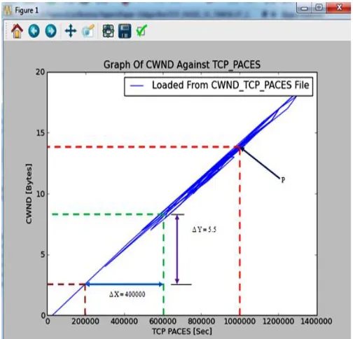
Figure 8: Congestion Window – TCP Paces Ramp Factor RF =
RESEARCH ARTICLE
In situations where multiple redundant routes exist from the source to the destination, the source machine probes the congestion level of each of these routes. Thereafter, the TCP paces are set dynamically such that congested routes are allocated smaller TCP paces due to smaller number of packets that have to be sent through these links. On the other hand, for less congested paths, large number of packets are transmitted. Consequently, TCP paces are set to be a bit large so as to allow the successful delivery of the sent data. In so doing, the developed algorithm is truly congestion aware. As was the case for the throughput – TCP paces graph, this is a near straight line graph. Therefore the relationship between the congestion window, Cwnd and the TCP paces can be expressed as shown in (6):
Cwnd = [RF * TCP pace]
(6) Where RF is the ramp factor.
The ramp factor for this graph was determined using (7):
𝛥 𝑌
𝛥𝑋
(7)
=
4000005.5 (8)This gives a value of 0.00001375 for the ramp factor. Therefore, at any observation instant, the relationship between the congestion window and the TCP paces is given by relation (9):
Cwnd [Bytes] = 0.00001375 * TCP Pace
(9)
To put this relationship into confirmation, point P in Fig. 6 was considered. At this point in time, the TCP pace value was 1000000. Hence, according to equation (9), congestion window size value should be equal to:
Cwnd [Bytes] = 0.00001375 * 1000000
(10)
The result of (10) is 13. 75 bytes, a very close approximate to 14 bytes, the point where the straight line emanating from point P cuts the Y-axis, the congestion window. Once again, (9) has been validated. The next graph to be plotted was that of the TCP paces against the transmission time as shown in Figure 9. As this Figure 9 shows, the value of the TCP paces varied continuously during the transmission time. It further demonstrates that higher TCP paces were allowed for some transmission times while very low TCP paces were permitted for other transmissions.
To put this into context, three points P, Q and R are considered. At point P, the TCP pace is at its highest value. Therefore, considering the zero-point as the reference point or the rest position, then A1 represents the highest amplitude and point P
can therefore be regarded as the crest for this graph during this observation period.
Figure 9: Variation of TCP Pacing Over Time
On the other hand, at point Q, the graph is at its lowest position and the value of network TCP pace is at its least. Once again, taking the zero-point as the reference point, then A2 represents
the least amplitude during the entire observation time. Therefore, point Q can be taken to be the trough for this graph during this time.
At point R, the graph is at its midway between zero-point reference and the crest. As such, amplitude A3 can be regarded
as the mean amplitude. This is because at this observation instant, majority of the TCP paces were above this point.
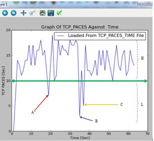
Figure 10: Observation Instant-1 TCP Pacing Threshold
RESEARCH ARTICLE
This is the dynamic TCP pacing that this study sought to develop for cloud communications. However, from this graph, it was possible to establish the TCP pacing value where most packet delivery was assured. This was accomplished by determining the point where most TCP paces were above a given straight line that then served as the threshold value as shown n Figure 10. As this Figure 10 clearly demonstrates, point R fell exactly on this green line.
This meant that the line moving from point R crossing the Y-axis, the throughput Y-axis, could serve as the threshold line and the value of the TCP pace where this line crossed the Y-axis could be considered as the threshold TCP pacing value. From Figure 10, this threshold TCP pace value was 10 seconds. At the threshold value of 10 seconds, majority of the TCP paces were well above this green line while only a few fell below this line. During the entire observation period, only at three observation instants A, B and C did the TCP paces went below the threshold line. The comparison of these three points against the great number of the points that were above this line led to the conclusion that the TCP pace of 10 seconds was established as the optimum TCP pacing value during the observation period. Using this threshold line, it was possible to cluster the TCP paces into two regions, labeled H and L. at region H, the TCP paces were large, implying that many data packets were transmitted at this region such that enough TCP pacing was carried to enable these packets to be delivered successfully. On the other hand, at region L, the TCP paces were less, the implication of which is that smaller number of packets were transmitted and the TCP pacing value were set to smaller values so that the network could be probed again to determine whether the conditions have improved to facilitate the transmission of larger number of packets.
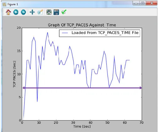
Figure 11: Observation Instant-2 TCP Pacing Threshold
However, it was possible for this threshold value to shift during another set of observation instants as illustrated in Figure 11. This Figure 11 clearly shows that the optimum TCP value has now shifted to 7 seconds as majority of the TCP paces now lie above this new value as demonstrated by the purple horizontal line.
Consequently, the optimum TCP pacing value depended on the prevailing network conditions. This was the dynamic TCP pacing that this paper was advocating for.
5. COMPARISON WITH OTHER TECHNIQUES In this section, the developed congestion aware packet routing algorithm is compared with the latest techniques for congestion and delay reduction in communication networks.
To start with, an adaptive auto-tuning of TCP pacing that adjusts the pacing speed dynamically introduces congestion window pacing, and estimated available bandwidth pacing. It suppresses burst transmission and restricts the excess growth of the congestion window size. The setback of this technique is that its congestion window pacing limits the data size during RTT period to only the size of cwnd. In addition, the estimated available bandwidth pacing restricts the maximum transmission speed to the anticipated available bandwidth at the last time of the packet loss. This is erroneous since network conditions might have improved since the last packet losses were detected. The proposed algorithm addresses these challenges by allowing transmissions speeds and data packet sizes to be dynamically adjusted based on the prevailing network conditions.
The second techniques employing acknowledgements for clocking transmission rates over the course of the first RTT has been suggested. The challenge of this method is that the acknowledgements may be attacker initiated, leading to erroneous clocking of transmissions. The suggested technique averts these attacks by utilizing RTT instead of acknowledgements to clock transmission rates.
On its part, Discrete Delay Function (DDF establishes new intermediate node in wireless sensor networks and then forwards packets through this best intermediate node. The only setback for this mechanism is that DDF requires the initial setting of the range, called concentric coronas. Any node in the network will then employ this inner corona to forward the packet, since it is the best intermediate node for forwarding the packet. On condition that no nodes could be found in a specific region, this function automatically searches another node in the next corona. The developed algorithm automatically probes for minimum cwnd, maximum cwnd and RTT only and then varies the transmission rates between these cwnd extremes. It does not require setting of concentric coronas.
RESEARCH ARTICLE
adjust those flows to a rate that the network and receiver can handle has also been employed to prevent bursty transmissions. The disadvantage of this technique is that it works only in Linux kernel which can be easily modified and recompiled, being an open source. The proposed dynamic TCP pacing works in Linux, Windows and other platforms and does not necessitate communication with operating system kernels. Another technique for delay reduction in all fiber core networks has been implemented at the router level. It serves to smoothen traffic bursts. However, this technique is only possible for router implementation and not for general internetworking devices. The suggested approach works for al internetworking devices with small packet buffers and large packet buffers. Google’s QUIC technique runs over User Datagram Protocol
(UDP and is optimized to be utilized for HTTP/2 connections. Its shortcomings are that its performance is optimized for HHTP/2. In addition, since it runs over UDP, it is connectionless, meaning that delivery of data transferred over it is not guaranteed. The algorithm proposed here runs on TCP, UDP and other communication protocols.
A novel cooperative transmission control mechanism, referred to as TCP-polite rate control (TPRC) is based on cooperative determination of new congestion indicator as a substitute for drop ratio and round-trip time. On the flip side, cooperative measurements generate extra overhead and can easily lead to congestions. In this new approach, the probe signals transit with the payload and hence do not create extra overhead.
6. CONCLUSIONS
This study aimed to develop an algorithm to dynamically change the value of TCP paces for delay sensitive networks. In these networks, any delays are highly undesirable and packet losses can be of catastrophic effect on the ongoing communication. The comparison of the developed pacing mechanism with other delay reduction mechanism has revealed that this algorithm outperforms these techniques in one way or the other. Since majority of the organizations host their data centers or online backups in third party cloud infrastructure, there is always a constant communication between company departments and the cloud data centers. In this scenario, packet loss or delays can negatively and adversely affect the company operations. This is one area where the developed algorithm can be effectively implemented.
The current TCP pacing avoids bursty transmissions, which might be sources of delays and packet losses. However, the pacing does not scale with the prevailing network conditions. In this new dynamic TCP pacing algorithm, the sender first probes the network to determine the prevailing conditions and dynamically adjusts the TCP pauses, congestion window, and throughput. This novel algorithm prevents delays by sending only a few packets are when TCP paces are long. This gives enough time for larger packets travelling between the
organization and the cloud to prevent them from being dropped before reaching their destinations. However, to prevent holding network resources for long duration, beyond a given TCP pacing threshold, the current packet sequence number is marked and logged for retransmissions. The simulation results obtained justifies the efficiency of this algorithm and it is therefore recommended for practical implementation on cloud environment.
REFERENCES
[1] Nouh, May Sayed A., et al. "Enhanced Route Discovery Mechanism of Ad-Hoc On Demand Distance Vector for MANET." International Journal of Computer Networks and Applications (IJCNA) 3.6: 129-138, 2016, DOI: 10.22247/ijcna/2016/48904
[2] N. Tanida, M. Inaba, and K. Hiraki, “Adaptive auto-tuning of TCP pacing”, The University of Tokyo, Hongo Bunkyo Tokyo, Japan, pp. 1-14, 2015.
[3] A. Aggarwal, S. Savage, and T. Anderson, “Understanding the Performance of TCP Pacing”, Department of Computer Science and Engineering University of Washington Seattle, pp. 1-9, 2015. [4] A.Nabil, T. Patrick, K. Robert, N. Vijay, M. Thomas, and B. Arkady, “
Secure and Resilient Cloud Computing for the Department of Defense”, Lincoln Laboratory Journal, Vol. 22, No. 1, pp. 123-135, 2016. [5] D. Sakhuja & A. Shukla, “Cloud Computing”, International Journal of
Engineering Research & Technology (IJERT), Vol. 2, Issue 3, pp. 1-7, 2013.
[6] B. Dennis, “Impact of Virtualization on Data Center Physical Infrastructure”, The Green grid, Vol. 27, pp. 1-10, 2010.
[7] S. Karolj, D. Davor, A. Enis, S. Ivan, S. Zorislav, “Scalable Distributed Computing Hierarchy: Cloud, Fog and Dew Computing”, Open Journal of Cloud Computing, Vol. 2 (1), pp. 16–24, 2015.
[8] M. Haghighat, S. Zonouz & M. Abdel-Mottaleb, “CloudID: Trustworthy Cloud-based and Cross-Enterprise Biometric Identification”, Expert Systems with Applications, Vol. 42, No. 21, pp. 7905–7916, 2015.
[9] C. Lehmann, “ Hybrid multi-cloud architecture, and the vendors aiming to enable and manage it”, 451 Research, LLC, pp. 1-6, 2016. [10] M. Duke, R. Braden, W. Eddy, E. Blanton & A. Zimmermann, “A
Roadmap for Transmission Control Protocol (TCP) Specification Documents”, Internet Engineering Task Force (IETF), pp. 1-57, 2015. [11] M. Ghobadi and Y. Ganjali, “TCP Pacing in Data Center Networks”,
IEEE 21st Annual Symposium on High-Performance Interconnects, pp. 1-8, 2013.
[12] K. Chaubey and P. Mistri, “An Encounter Based Routing in Delay Tolerant Network (DTN): A Hybrid Approach”, International Journal Of Innovative Research In Computer And Communication Engineering, Vol. 4, Issue 5, pp. 8657 - 8662 , 2016. DOI: 10.15680/IJIRCCE.2016. 0405085.
[13] N. Dayanand and A. Vidhate, “Improved Routing Protocol for Delay Tolerant Network”, International Journal of Advanced Research in Computer Science and Software Engineering, Vol. 6, Issue 4, pp. 688- 691, 2016.
[14] S. Islam and M. Welzl, “Start Me Up: Determining and Sharing TCP’s Initial Congestion Window”, ACM, pp. 1-3, 2016. DOI: http://dx.doi.org/10.1145/2959424.2959440.
[15] Rohini, G., and A. Srinivasan. "Dynamic Transition of Bandwidth and Power Saving Mechanism to Support Multimedia Streaming Using H. 264/SVC over the Wireless Networks." International Journal of Computer Networks and Applications 2.2 (2015): 57-63.
RESEARCH ARTICLE
[17] N. Hanford, B. Tierney and D. Ghosal, “Optimizing Data Transfer Nodes using Packet Pacing”, ACM, pp. 1-8, 2015, DOI: http://dx.doi.org/10.1145/2830318.2830322.
[18] Y. Cai, Y. Sinan and T. Wolf, “Practical Packet Pacing in Small-Buffer Networks”, Department of Electrical and Computer Engineering University of Massachusetts, pp. 1-6, 2016.
[19] F. Gratzer, “QUIC - Quick UDP Internet Connections”, Seminars FI / IITM SS 16, Network Architectures and Services, pp. 36-46, 2016, DOI: 10.2313/NET-2016-09-1_06.
[20] W. Wang, L.Huang, C. Li, and X. Wang, “TCP-polite rate control based on cooperative measurement”, John Wiley & Sons, Ltd, Vol. 9, Issue 9 , pp. 899–909 ,2013, DOI: 10.1002/sec.901.
Authors
Vincent O. Nyangaresi is a student researcher in areas of data communication and computer networks, network design and administration, distributed systems and information systems security. He has published numerous research articles covering areas such as communication systems, secure network communications, systems acceptance modeling, TCP architecture and design, radio wave propagation, virtualization and cloud computing, among others.
Dr. Silvance O. Abeka is currently the Dean, School Of Informatics And Innovative Systems, Jaramogi Oginga Odinga University of Science And Technology.He holds a masters degree in Business Administration (Information Technology) and a PhD in Management Information Science (MIS), from Kampala International University, Dar es Salaam Collage. His interests include Management Information Systems, Principles of Statistics and E- Commerce. He is also a lecturer in the school of Computer Studies.