© 2018 IJSRSET | Volume 4 | Issue 1 | Print ISSN: 2395-1990 | Online ISSN : 2394-4099 Themed Section : Engineering and Technology
CAD Modelling and Finite Element Analysis of Multistage
Three Roller Pipe Bending Machine-Design
Payal Mane1, Dr. C. C. Handa2, V. N. Mujbaile3
1M.Tech Student of Mechanical Engineering Department KDKCE, Nagpur, Maharashtra, India
2Professor of Mechanical Engineering Department KDKCE, Nagpur, Maharashtra, India
3Assistant Professor of Mechanical Engineering Department KDKCE, Nagpur, Maharashtra, India
ABSTRACT
This paper deals with cad modelling and finite element analysis of multistage three roller pipe bending machine. This paper gives the cad model for existing and multistage three roller pipe bending machine. Cad modelling is helpful for safe designing a machine and also for further study. This cad model is then meshed in HYPERMESH for finite element modelling and analysis. The results of finite element analysis are very important part for designing the machine.
Keywords : CAD, FEA
I.
INTRODUCTION
Computer-aided design (CAD) is the use of computer systems to aid in the creation, modification, analysis, or optimization of a design. CAD software is used to increase the productivity of the designer, improve the quality of design, improve communications through documentation, and to create a database for manufacturing. CAD output is often in the form of electronic files for print, machining, or other manufacturing operations.
In mechanical design it is known as mechanical design automation (MDA) or computer-aided design (CAD), which includes the process of creating a technical drawing with the use of computer software. Finite element analysis (FEA) involves solution of engineering problems using computers. Engineering structures that have complex geometry and loads, are either very difficult to analyse or have no theoretical solution. However, in FEA, a structure of this type can be easily analysed. Commercial FEA programs, written so that a user can solve a complex engineering problems without knowing the governing equations or the mathematics; the user is required only to know
the geometry of the structure and its boundary conditions. FEA software provides a complete solution including deflections, stresses, reactions, etc.
II.
CAD MODELLING
The importance of modeling and simulation in manufacturing technology is increasing due to the need for continuous reduction of development time. This necessitates the optimization of the production processes, the enhancement of product quality and a reduction of costs. The application of numerical modeling is especially resorted to in the development of new production methods and in the use of new materials. Specialized software solutions are available to optimize the design of castings (solidification analysis), welding process (resistance welding, gas metal arc welding), heat treatment and metal forming (sheet metal processing, tube bending, extrusion, rolling, drawing, forging etc).
Figure 1. Existing pipe bending machine (CAD model)
The above figure shows the cad model of three roller pipe bending machine. It shows the three rollers, two of which are movable and powered by motor. There is also a third roller which is adjustable and it can be moved with the help of hydraulic press.
Figure 2. Orthographic view of existing pipe bending machine
The above figure shows the orthographic view of three roller pipe bending machine. It shows the front view, top view, and left and right side views. It also shows the dimensions of the machine.
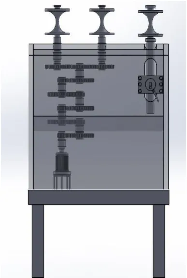
Figure 3. Transparent view of existing pipe bending machine
The above figure shows the exploded view of three roller pipe bending machine. It shows the different parts of the machine and where it is attached.
2.1 Bill of material
Sr. No.
Component No. Of
Component
1 ENCLOSURE 1
2 TABLE 1
3 GEAR-BOX 1
4 HYDRAULIC-PRESS 1
5 ROLLER 3
6 SPURE-GEAR-1 7
7 SPUR-GEAR-2 3
8 SPUR-GEAR-3 7
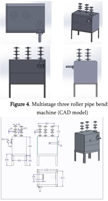
Figure 4. Multistage three roller pipe bending machine (CAD model)
Figure 5. Orthographic view of multistage three roller pipe bending machine
III.
FINITE ELEMENT MODELLING
A finite element analysis of three roller pipe bending machine is done in the software.
Basic steps in analyzing:
(i) Initially, choose static structural from analysis systems.
(ii) Import the assembly model is to be analyzed. (iii) Choose the engineering data and add required number of materials. Enter the material properties like tensile strength, compressive strength, ultimate tensile strength, density.
(iv) Open the model and choose the corresponding material for each part of the model.
(v) Mesh the model by using quadrilateral or all triangular elements.
(vi) Boundary conditions are applied to the machine. (vii) The total load of should apply on the rollers. (viii) Under solution choose total deformation, Stress and Strain.
(ix) Solve the model. (x) View the results.
3.1 Boundary Conditions
Boundary conditions are a set of loading, constraints and contact conditions that define the status of your simulation in one possible design configuration. They are an essential component of the FEA System.
The boundary condition is the application of a force and/or constraint. In Hypermesh, boundary conditions are stored within what are called load collectors. There are two collectors one for constraint and second for force.
Constraints:
Figure 6. Single stage three roller pipe bending machine showing boundary conditions applied to the
Figure 7. Multistage three roller pipe bending machine showing boundary conditions applied to the
machine
The above figure shows the boundary conditions that are applied to the machine. The red colour shows that the end is fixed as the machine is fixed at the bottom. Also the bottom of the hydraulic press is fixed as shown in the figure.
Forces:
The forces applied on the finite element model at a specified key point.
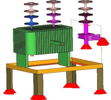
Figure 8. Single stage three roller pipe bending machine showing forces acting on the machine
Figure 9. Multistage three roller pipe bending machine showing forces acting on the machine
The above figure shows the transparent view of three roller pipe bending machine in which the forces that are applied on the roller are also shown.
Fea Results (Static)
The FEA results of the existing three roller pipe bending machine and modified multistage three roller pipe bending machine are given below.
Displacement:
Maximum displacement in existing pipe bending machine structure = 0.25 mm
Stresses:
The following results gives the maximum displacement and stresses that are occurring in the multistage three roller pipe bending machine.
Maximum displacement in existing pipe bending machine structure = 2.76 mm
Maximum stresses in existing pipe bending machine structure = 166 MPa
SR.No. Existing Pipe Bending Machine
Results
1. Displacement 0.25mm
2. Stress 64.8MPa
SR.No. Modified Pipe Bending Machine
Results
1. Displacement 2.76mm
2. Stress 166MPa
IV.
CONCLUSION
Thus, the design and analysis of existing pipe bending machine is carried out. Displacement and stresses on the machine are also found out. The dimensions of the machine and its parts are found to be safe and hence validated.
V.
REFERENCES
[1]. "Review paper on design of multistage three roller pipe bending machine for C. B. Industry Nagpur"-Payal Mane, C.C. Handa, V. N. Mujbaile, department of mechanical engineering, KDK college of engineering, Nagpur
[2]. "Design of multistage three roller pipe bending machine"-Payal Mane, C. C. Handa, V. N. Mujbaile, Department of mechanical engineering, kdk college of engineering.
[3]. "Development of a hydraulically operated pipe bending machine"-olafimihan. E. O-Department of Mechanical Engineering, LadokeAkintola University of Technology, Ogbomosho, Nigeria
[4]. "Study of portable 3 roller pipe bending machine" Prashant P.Khandare1 , DhiralN.Patel2 , Mayur K.Aher3 , Ravi S.Parbat4 , Prof. Swapnil S. Patil5 1,2,3,4Scholar student of B.E(mechanical engg.)Pune University.
[5]. "Review on Design and Analysis of Portable Rolling and Bending Machine"-Pooja K. Borkar1 Prof. Pankaj H. Meshram2 1M.E. Scholar 2Assistant Professor 1,2Department of Mechanical Engineering 1,2 JCOET, Yavatmal [6]. "Experimental design and fabrication of a
portable hydraulic pipe bending machine"-Mohan Krishna S. A.- Department of Mechanical Engineering, Vidyavardhaka College of Engineering, Mysore-570002, Karnataka, India
[7]. "Research Paper of Manually Operated Pipe Bending Machine"-N. N. JADEJA-Assistant Professor, Government Engineering College, Bhavnagar- 364002