University of South Carolina
Scholar Commons
Theses and Dissertations
2017
Progressive Failure Analysis of composite Materials
using the Puck Failure Criteria
Karan Kodagali
University of South Carolina
Follow this and additional works at:https://scholarcommons.sc.edu/etd
Part of theMechanical Engineering Commons
This Open Access Dissertation is brought to you by Scholar Commons. It has been accepted for inclusion in Theses and Dissertations by an authorized administrator of Scholar Commons. For more information, please [email protected].
Recommended Citation
P
ROGRESSIVEF
AILUREA
NALYSIS OFC
OMPOSITEM
ATERIALS USING THEP
UCKF
AILUREC
RITERIAby
Karan Kodagali
Bachelor of Science
Gogte Institute of Technology, 2013
Submitted in Partial Fulfillment of the Requirements
For the Degree of Master of Science in
Mechanical Engineering
College of Engineering and Computing
University of South Carolina
2017
Accepted by:
Addis Kidane, Director of Thesis
Subramani Sockalingam, Reader
© Copyright by Karan Kodagali, 2017
ACKNOWLEDGEMENTS
Firstly, I would like to express my sincere gratitude to my advisor Dr. Addis Kidane
for the continuous support of my research, for his patience, motivation, and immense
knowledge. His guidance helped me in all the time of research and my masters.
I thank my fellow labmates, Addis Tessema and Suraj Ravindran for the stimulating
discussions over the past three years. Their invaluable experimental knowledge has helped
me to understand different concepts and behavior of composite materials
Lastly, I would like to thank my family for supporting me throughout my masters,
ABSTRACT
Fiber reinforced composites have been used in various engineering structures and
applications especially in naval, automotive, aeronautical and sports industries. These
composite materials generally exhibit brittle damage behavior. The anisotropy in the
material and different kinds of failure mechanisms make it difficult to accurately
characterize the behavior of composite materials. The present work aims to verify and
apply the Puck Failure Criteria using the commercially available finite element package
ABAQUS by writing a user-material subroutine in FORTRAN. The model is implemented
with different post failure degradation schemes.
In the present work, the progressive failure on composite materials in analyzed
using the Puck failure criteria to detect damage initiation. The ABAQUS user defined
material subroutine UMAT was developed to apply the failure criteria and degradation
models. The progressive failure analysis of a single lamina of a composite material is
carried out on an open hole specimen under uniaxial tension. A partial discount method
and a gradual stiffness degradation method is implemented and the results using these
degradation models are compared. The damage initiation and progression obtained from
the proposed model is compared with the observed experimental results and the digital
image correlation data. This model was then used for the progressive failure analysis of a
composite laminate with a central hole loaded in inplane tension with different stacking
From the results, it can be seen that the Puck failure hypothesis is a robust and
versatile criteria which can be used for the progressive failure analysis of continuous fiber
T
ABLE OFC
ONTENTSACKNOWLEDGEMENTS ... iii
ABSTRACT ... iv
LIST OF FIGURES ... vii
LIST OF TABLES ... viii
LIST OF ABBREVIATIONS ... ix
CHAPTER 1:INTRODUCTION ...1
CHAPTER 2:LITERATURE REVIEW ...5
CHAPTER 3:THEORY ...16
CHAPTER 4:PROGRESSIVE FAILURE ANALYSIS OF A COMPOSITE LAMINA USING PUCK FAILURE CRITERIA ...26
CHAPTER 5:PROGRESSIVE FAILURE ANALYSIS OF A COMPOSITE LAMINATE USING THE PUCK FAILURE CRITERIA ...44
CHAPTER 6:SUMMARY AND RECOMMENDATIONS ...63
BIBLIOGRAPHY ...65
L
IST OFF
IGURESFigure 3.1 Different Scales of Analysis ...18
Figure 3.2 Different forms of Fiber Fracture (FF) ...19
Figure 3.3 Different forms of Inter Fiber Fracture (IFF) ...22
Figure 3.4 Stresses acting on the fracture plane ...23
Figure 4.1 Test specimen Configuration. ...39
Figure 4.2 Algorithm for ABAQUS subroutine ...40
Figure 4.3 Experimental and Finite Element strain distribution at 2508N. ...41
Figure 4.4 Matrix damage propagation at different load steps using EWM. ...42
Figure 4.5 Matrix damage propagation at different load steps using CSE. ...42
Figure 4.6 Image taken after failure of 0-degree specimen (b) close-up of specimen. ...43
Figure 5.1 Algorithm for ABAQUS subroutine ...55
Figure 5.2 Geometry and Boundary conditions of the laminate. ...57
Figure 5.3 Damage propagation in 0 degree layer ...59
Figure 5.4 Damage propagation in 45 degree layer ...59
L
IST OFT
ABLESTable 3.1: Recommended Values for Inclination Parameters ...24
Table 4.1: Recommended Values for Inclination Parameters. ...33
Table 4.2: Dimensions Of The Test Specimen. ...36
Table 5.1: Recommended Values for Inclination Parameters ...52
Table 5.2: Material Properties of T300/1034C ...56
Table 5.3: Dimensions of The Composites. ...56
L
IST OFA
BBREVIATIONSDIC ... Digital Image Correlation
FF ... Fiber Failure
FEA ... Finite Element Analysis
IFF ... Inter Fiber Failure
UMAT ... User Material Subroutine
CHAPTER 1
INTRODUCTION
1.1 BACKGROUND
Composite materials are materials made from two or more constituent
materials with significantly different material properties combined to make a superior
material with unique properties. Composites occur naturally, for example wood found in
nature and even the bones in every skeletal system are composite materials. Composites
have been used as building materials for thousands of years. Mud bricks have been
reinforced with straw materials which provide more tensile strength than conventional mud
bricks. Concrete is also a composite material, it is a mixture of aggregate, cement and sand.
Most modern composites are made of two materials – fibers which provide strength and
carry a bulk of the tensile load and a matrix or binder material to reinforce the fibers.
Recently fiber reinforced composites have been used in various engineering
structures and applications especially in naval, automotive, aeronautical and sports
industries. The Boeing 787 Dreamliner and the Airbus A380 are large capacity passenger
airplanes and make use of composite materials owing to the high stiffness to low weight,
high tensile strength, non-corrosive properties and the fact that composite materials have
different properties in different directions, makes it possible for the materials to be
tailormade specifically for the product requirement. Carbon fiber reinforced composite
These composite materials generally exhibit brittle damage behavior. There is little
plastic deformation and failure occurs suddenly. The anisotropy in the material and
different kinds of failure mechanisms make it difficult to accurately characterize the
behavior of composite materials.
A number of failure criteria were proposed to describe the damage in
composite materials. Section 2 of this thesis deals with the literature review wherein a brief
review of many of the progressive failure models are provided. In the early 90s, the
World-Wide Failure Exercise (WWFE) was initialized and to provide a comprehensive
coordinated study of the predictive capabilities of prominent failure criteria currently in
use to describe the behavior of fiber reinforced laminates. The authors of many of the
failure criteria were invited to provide blind predictions for different cases and then these
predictions were evaluated against other predictions and the experimental data. The first
exercise, WWFE I dealt with 2D stress cases with 19 failure criteria being evaluated [1].
The second exercise, WWFE II dealt with 3D stress cases with 12 criterions being
evaluated [2]. The third exercise WWFE III dealt with laminates with a stress concentration
under inplane loading conditions [3]. From the results of the WWFE I and WWFE II, there
was no clear consensus on the best performing failure criteria for all the different load cases
however, it showed the strengths and the shortcomings of the criteria. The Puck Failure
Criteria was found to perform well for most of the test cases.
1.2 OBJECTIVE
Though the performance of composite materials is very good, it presents a
work aims to apply the Puck Failure Criteria using the commercially available finite
element package ABAQUS by writing a user-material subroutine in FORTRAN to
simulate the progressive failure of continuous fiber unidirectional composite materials. The
model is implemented with different post failure degradation schemes. The model is
validated against an experiment conducted on a single layer lamina with a central hole
loaded in inplane tension. The Digital Image Correlation (DIC) data and the experimental
data were compared with the model prediction. Another validation test was conducted by
comparing failure loads for a group of composite laminates with a central hole and different
1.3 LIST OF REFERENCES
[1] Hinton, M.J. and Kaddour, A.S. and Soden, P.D.: Failure Criteria in Fibre Reinforced Polymer Composites, The World-Wide Failure Exercise. Amsterdam:Elsevier 2004
[2] Hinton, M.J.Benchmarking of triaxial failure criteria for composite laminates: Comparison between models of ‘Part (A)’ of ‘WWFE-II’ JOURNAL OF COMPOSITE MATERIALS, 46(19–20) 2595–2634,2012
CHAPTER 2
LITERATURE REVIEW
This section provides a brief review of the various progressive failure models
available in literature.
W Van Paepegem and J Degrieck [1] have proposed a residual stiffness model
which simulates the full cycle from initial decline to final failure. The modified Tsai-Wu
criterion by Tsai-Liu was further modified to determine the calculated safety factor and
then defined the fatigue failure index which can be accepted as a suitable stress measure.
The model was developed as two functions - damage initiation and damage propagation
and the final layout of the model was a superposition of the two functions. The model
developed is one-dimensional in nature, only longitudinal stiffness is considered and
delamination’s have not been included in the model.
C. Schuecker and H.E. Pettermann [2] proposed a continuum damage model based
on brittle failure mechanisms. They hypothesized that any non-linear material behavior
was the result of brittle cracks forming in the composites. Puck 2D criterion was employed
to determine failure modes and damage growth. First, the current damage on the current
load measure is computed and then, the effect of damage on the elasticity tensor is predicted
by a fourth order tensor equation also taking into account the current stress state. The
laminate response predicted by this model is too stiff under shear dominated loading
Mahmood M Shokrieh and Larry B Lessard [3] proposed a model capable of
simulating the fatigue behavior of laminated composites under general loading conditions,
with or without stress concentrations. This model can determine the residual strength,
residual stiffness and fatigue life of composite laminates with arbitrary geometry and
stacking sequence under complicated fatigue loading conditions. Failure modes were
determined by Hashin’s criteria.
S C Tan and R J Nuismer [4] proposed a progressive matrix cracking model in
which the laminate is assumed to contain periodic cracks with even spacing. A plane stress
assumption and a generalized plane stress assumption were employed. The salient feature
about this model is that it requires basic material properties such as moduli, Poisson ratio,
thermal expansion coefficients and the specific fracture energy. This model is only
applicable under the given assumptions.
Fu-Kuo Chang and Kuo-Yen Chang [5] proposed a damage model for notched
laminates subjected to tensile loads with any arbitrary ply orientations. The 2D plane stress
assumption was used and loads were assumed to increase incrementally in small steps such
that the stress-strain relations were assumed to be linear. A finite element method combined
with a Newton-Raphson scheme was developed to solve the model.
F Cesari, V Dal Re, G Minak and A Zucchelli[6] have proposed a damage model
for carbon-fiber reinforced epoxy-resin laminates loaded at the center to simulate low
velocity impacts. The 3D Hashin criteria were used to determine the individual damage
modes. A numerical model to predict the first ply failure and the ultimate ply failure of the
Dahlen C and Springer G S [7] proposed a semi-empirical model to determine the
growth of delamination in laminates under cyclic loading and mode I, mode II and mixed
mode conditions. Mode III was assumed to not contribute significantly to delaminations.
A growth law similar to Paris growth law was employed.
Xiao J and Bathias C [8] studied notched and un-notched woven composites with
mechanical properties the warp direction being much higher than those in the weft. They
showed that the ratios between fatigue strength and ultimate tensile strength for both
notched and un-notched cases are equal to their respective static strength ratios.
H A Whitworth [9] proposed a model to predict the stiffness degradation in
composite laminates based on an assumed relation between the failure stiffness and the
applied stress. The statistical distribution of the residual stiffness is obtained from a
2-parameter Weibull distribution. The theoretical distribution over-predicts in some cases,
the accuracy improves with increasing cycle number. The present model is only limited to
specimens subjected to constant amplitude fatigue loading and assumes that the residual
stiffness is a monotonically decreasing function of the fatigue cycles.
Alexandros E Antoniou, Christoph Kensche and Theodore P Philippidis [10]
proposed 3 different models, one implements the Puck’s failure criteria and associated
progressive stiffness degradation rule, the second one is based on Lessard and Shokrieh
limit theory while the third is similar to the first, implements Puck’s IFF criteria and
associated gradual stiffness degradation rules however having different conditions for fiber
breakage. Failure modes were restricted to 2D in plane patterns. Elastic modulus in the
P C Wang, S M Jeng and J M Yang [11] studied the stiffness reduction and
evolution of microstructural damage of a unidirectional composite under tension-tension
fatigue. A partial crack shear-lag model developed by Kuo and Chou for ceramics was
adopted and modified for application in metal composites to predict residual stiffness as a
function of fatigue damage evolution. The fiber matrix interfacial bonding was assumed to
be perfect. The results suggest that the matrix crack density controls the stiffness
degradation profile. The residual stiffness is independent of the applied stress levels
however the accumulation of microstructural damage varies with the applied stress.
J N Yang, D L Jones, S H Yang and A Meskini [12] proposed a stiffness
degradation model to predict the statistical distribution of the residual stiffness of
composites subjected to fatigue loading. Two analytical methods were presented, one based
on linear regression analysis and the other on the Bayesian approach. The results are only
accurate if fatigue life data already exists up to 50% of the fatigue life.
K I Tserpes, P Papanikos and Th Kermanidis [13] proposed a 3-D progressive
damage model to simulate the damage accumulation and predict the residual strength and
final failure mode of bolted composite joints under in-plane tensile loading. The 3D Hashin
failure criteria as reported by Shokrieh and Lessard was used to predict failure. Material
property degradation rules as proposed by S C Tan were used.
T Kevin O’Brien and Kenneth L Reifsnider [14] proposed a secant modulus
criterion that would predict fatigue failure of the laminate while tests were being carried
out. When the static stiffness measured during fatigue, Ef degrades from its initial tangent
valid failure criterion for general application but can be applied to only specific laminate
orientations.
C D M Liljedahl, A D Crocombe, M A Wahab and I A Ashcroft [15] proposed a
numerical modelling techniques for predicting the environmental degradation of
adhesively-bonded joints. A CZM was implemented in the FEA by use of a user-defined
element (UEL). The CZM parameters were determined by correlating experimental data
and numerical predictions for initial failure loads.
W Hwang and K S Han [16] proposed a new concept called "fatigue modulus,"
which is defined as a slope of applied stress and resultant strain at a specific cycle. They
assumed that the fatigue modulus degradation follows a power function of the fatigue
cycles. The fatigue life was determined from the fatigue modulus and was found to have a
better agreement with experimental data than the S-N curves and Basquin’s relation.
Stephen R Hallet and Michael R Wisnom [17] proposed a new approach to
modelling of notched composite materials using interface elements to model the inter and
intra ply damage. This method was developed to model delamination in composites. It can
be used to predict the initiation and propagation of the delamination, however it requires a
prior knowledge of the potential failure sites.
Timothy W Coats and Charles E Harris [18] experimentally verified a continuum
damage model which was used to predict the development of progressive damage in a
toughened material system. The Allen and Harris model was employed to model the
behavior of micro-crack damage by predicting stiffness loss and damage in a laminate. .
The model neglects edge effects, uses internal state variables to represent the local
A S Koumpias , K I Tserpes and S Pantelakis [19] developed a progressive damage
model to simulate the mechanical response, predict the quasi static strength of a fully
interlaced 3D woven composite and predict the damage initiation and progression as a
function of the applied load as well as the stiffness and strength of the composite. The
Hashin type failure criteria were used to predict the failure modes. To model the
mechanical response of the matrix, the multi-linear isotropic hardening material model
developed by Rolfes et al was used in the progressive damage model. The predicted failure
pattern for longitudinal tension is in complete agreement with the tests from that of Stig
and Hallstrom
Yuang Liang, Hai Wang, Costas Soutis, Tristan Lowe and Robert Cernik [20]
conducted quasi-static punch shear tests on satin weave carbon/epoxy laminates in an effort
to determine the damage that could develop during a penetrating impact event. The Hashin
criteria was employed as the failure criteria. Once damage occurs in an element based on
the Hashin criteria, a ply-discount degradation of material property was applied as the
damage progression strategy. A constant parameter, βk was used as the damage variable in
the stiffness reduction method. Using a function instead of a constant as the damage
variable would yield better results.
M Ridha, C H Wang, B Y Chen and T E Tay [21] developed a progressive failure
model for orthotropic composite laminates to predict the effect of specimen size and
laminate orthotropy on the open-hole tension (OHT) strength. The max stress failure
criterion is combined with the Tsai-Wu failure criterion to model fiber-dominated and
specimen having four 0˚ plies because the stiffness and strength of laminates increases as
the percentage of 0˚ plies increases.
John Montesano, Marina Selezneva, Martin Levesque and Zouheir Fawaz [22]
developed a fatigue prediction model to predict damage tolerance capability of polymer
matrix composite structures. The model accounts for local multi-axial as well as variable
amplitude cyclic loading. The continuum damage model (CDM) developed also
incorporates a cumulative damage law that is a function of the number of loading cycles.
The model assumes that during unloading, the material properties are same as the
undamaged materials, suitable failure criteria’s are not defined. The model also assumes
that compressive stresses do not cause any damage and thus do not affect material stiffness.
Ciaran R Kennedy, Conchur M O Bradaigh and Sean B Leen [23] presented a
model that combines the fatigue induced fiber strength and modulus degradation,
irrecoverable cyclic strain effects and inter fiber fatigue. The predicted response captures
the overall modulus degradation in the first cycle and the evolution of degradation in
subsequent cycles until failure however, delamination was not considered as a failure
mode.
C T McCarthy , R M O’Higgins and R M Frizzell [24] developed a novel approach
where a cubic spline interpolation method was used to capture the non-linear shear
behavior. A ply discount method based of Hashin’s criteria was employed to determine the
damage, also the spline approach along with the maximum strain failure criteria was
employed to predict the shear response. This model accurately predicts tensile strength and
modulus but under-predicts the ultimate transverse strain. But only when shear stresses
Brett A Bednaryck, Bertram Stier, Jaan-W Simon and Evan J Pineda [25] presented
a comparison between the meso scale and micro scale approaches to modelling progressive
damage in plain weave reinforced polymer matrix composites. A continuum damage model
was developed and implemented based on the 2-D approach given by Barbero and was
extended for 3-D case. The damage model is based on the principle of energy equivalence
with infinitesimal strains. The micromechanics model was based on the generalized
method of cells (GMC) developed by Paley and Aboudi. It is an efficient semi-analytical
method that provides homogenized, non-linear constitutive response of a composite
material. Very similar results were obtained using the two approaches, however these
models were not compared with any experimental results.
Bartley-Cho J, Lim S G, Hahn h T and Shyprykevich P [26]studied the behavior
of quasi-isotropic graphite epoxy laminates. The authors obtained a failure function which
varies with number of cycles following an experimentally determined relationship to
predict ply cracking. The crack density was calculated, and it was found that in absence of
other competing damage modes, the crack density increased with applied load levels which
is opposite to the belief that crack density is independent of load history.
Talreja R [27] presented a continuum damage model where internal damage
variable are characterized by tensorial quantities. Matrix cracking and delamination were
the only damage modes considered, and it was assumed that these damage modes do not
mutually interact but were accounted for separately one damage mode at a time and the
2.1 LIST OF REFERENCES
[1]. W Van Paepegem and J Degrieck, ‘A new coupled approach of residual stiffness and strength for fatigue of fibre-reinforced composites’, International Journal of Fatigue (2002), 24:747–762.
[2]. C. Schuecker and H.E. Pettermann, ‘Fiber Reinforced Laminates: Progressive Damage Modeling Based on Failure Mechanisms’, Arch Comput Methods Eng (2008), 15: 163–184
[3]. Mahmood M Shokrieh and Larry B Lessard, ‘Progressive Fatigue Damage Modeling of Composite Materials, Part I: Modeling’, Journal of Composite Materials (2000), 34:1056-1080
[4]. S C Tan and R J Nuismer, ‘A Theory for Progressive Matrix Cracking in Composite Laminates’, Journal of Composite Materials (1989), 23:1029-1047
[5]. Fu-Kuo Chang and Kuo-Yen Chang, ‘A Progressive Damage Model for Laminated Composites Containing Stress Concentrations’, Journal of Composite Materials (1987), 21:834-855
[6]. F Cesari, V Dal Re, G Minak and A Zucchelli, ‘Damage and residual strength of laminated carbon-epoxy composite circular plates loaded at the center’, Composites: Part A (2007), 38:1163–1173
[7]. Dahlen C and Springer G S, ‘Delamination growth in composites under cyclic loading’, Journal of Composite Materials (1994), 28:732-781
[8]. Xiao J and Bathias C, ‘Fatigue behavior of un-notched and notched woven glass/epoxy laminates’, Composites Science and Technology (1994), 50:141-148
[9]. H A Whitworth, ‘A stiffness degradation model for composite laminates under fatigue loading’, Composite Structures (1998), 40.2:95-101
[10]. Alexandros E Antoniou, Christoph Kensche and Theodore P Philippidis,
‘Mechanical behavior of glass/epoxy tubes under combined static loading, validation of FEA progressive damage model’, Composites Science and Technology (2009), 69:2248– 2255
[11]. P C Wang, S M Jeng and J M Yang, ‘Characterization and modeling of stiffness reduction in SCS-6-Ti composites under low cycle fatigue loading’, Materials Science and Engineering (1995), A200:173-180
[13]. K I Tserpes, P Papanikos and Th Kermanidis, ‘A three-dimensional progressive damage model for bolted joints in composite laminates subjected to tensile loading’, Fatigue and Fracture of Engineering Materials and Structures (2001), 24:663–675
[14]. T Kevin O’Brien and Kenneth L Reifsnider, ‘Fatigue Damage Evaluation through Stiffness Measurements in Boron-Epoxy Laminates’, Journal of Composite Materials (1981), 15:55-70
[15]. C D M Liljedahl, A D Crocombe, M A Wahab and I A Ashcroft, ‘The effect of residual strains on the progressive damage modelling of environmentally degraded adhesive joints’, Journal of Adhesion Science and Technology (2012), 7:525-547
[16]. W Hwang and K S Han, ‘Fatigue of Composites - Fatigue Modulus Concept and Life Prediction’, Journal of Composite Materials (1986), 20:154-165
[17]. Stephen R Hallet and Michael R Wisnom, ‘Numerical Investigation of Progressive Damage and the Effect of Layup in Notched Tensile Tests’, Journal of Composite Materials (2006), 40:1229-1245
[18]. Timothy W Coats and Charles E Harris, ‘Experimental Verification of a Progressive Damage Model for IM7/5260 Laminates Subjected to Tension-Tension Fatigue’, Journal of Composite Materials (1995), 29:280-305
[19]. A S Koumpias , K I Tserpes and S Pantelakis, ‘Progressive Damage Modeling of 3D Fully Interlaced Woven Composite Materials’, Fatigue and Fracture of Engineering Materials and Structures (2014), 37:696-706
[20]. Yuang Liang, Hai Wang, Costas Soutis, Tristan Lowe and Robert Cernik, ‘Progressive Damage in Satin Weave Carbon/Epoxy Composites under Quasi-Static Punch Shear Loading’, Polymer Testing (2015), 41:82-91
[21]. M Ridha, C H Wang, B Y Chen and T E Tay, Modeling Complex Progressive Failure in Notched Composites Laminates with Varying Sizes and Stacking Sequence’, Composites: Part A (2014), 58:16-23
[22]. John Montesano, Marina Selezneva, Martin Levesque and Zouheir Fawaz, ‘Modeling Fatigue Damage Evolution in Polymer Matrix Composite Structures and Validation Using in-situ Digital Image Correlation’, Composite Structures (2015), 125:354-361
[24]. C T McCarthy , R M O’Higgins and R M Frizzell, ‘A Cubic Spline
Implementation of Non-Linear Shear Behavior in Three-Dimensional Progressive Damage Model for Composite Laminates’, Composite Structures (2010), 92:173-181
[25]. Brett A Bednaryck, Bertram Stier, Jaan-W Simon and Evan J Pineda, ‘Meso- and Micro-Scale Modeling of Damage in Plain Weave Composites’, Composite Structures (2015), 121:258-270
[26]. Bartley-Cho J, Lim S G, Hahn h T and Shyprykevich P, ‘Damage accumulation in quasi-isotropic graphite/epoxy laminates under constant amplitude fatigue and block loading’, Composites Science and Technology (1998), 58:1535-1547
CHAPTER 3
THEORY
3.1 SCALE OF THE ANALYSIS
The analysis of the composite materials can be conducted at four different scale –
micro-mechanical, lamina level, laminate level and structural level [1]. The
micromechanical level considers the fibers and matrix separately, each having different
properties and different behavior. The interaction between the fibers and matrix is
considered. In the lamina level, the fibers and matrix are treated as homogeneous
anisotropic materials. Orthotropic material models are generally used at this scale. Most of
the failure criteria are developed at this level and are considered in a layer-wise manner for
intralaminar failure [2]. On the laminate level, the material is observed as a stack of several
laminas, including interfaces. At this level, inter-laminar and intra laminar stresses are
obtained for each layer and also for the interfaces. Intra laminar failure analysis and
delamination is conducted at this level. On the structural level, whole components of the
structure are considered. These may involve complex local stacking sequences and
geometries of the component. In the current work, the Puck failure criteria is utilized at the
lamina scale and delamination failure has not been considered.
The constitutive models relate the state of strain to the state of stress. The model
used in a three-dimensional material model for a linear elastic and orthotropic material.
Figure 3.1 Different Scales of Analysis
3.2 PUCK FAILURE CRITERIA
Fiber reinforced composites usually display brittle fracture mechanics wherein the
fracture occurs suddenly without major plastic deformation. The macroscopic failure of a
composite can be seen at the lamina scale. This appears as fiber fracture (FF) or inter fiber
fracture (IFF). The Puck theory presents separate equations for the FF and IFF.
3.2.1 FIBER FAILURE
The fiber failure generally is regarded as the final failure of the lamina. Fiber failure
is defined as the simultaneous breakage of a large number of elementary fibers [3]. The
fibers have a much higher stiffness than the matrix and carries much higher loads in the
fiber direction. However, transverse to the fiber direction, nearly the same amount of stress
acts on both the fiber and the matrix. The fiber failure is considered as a statistical process.
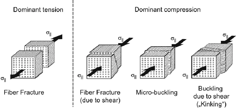
Figure 3.2 Different forms of Fiber Fracture (FF)
Figure 3.2 illustrates the different fiber fracture modes. Under a tensile load, the
fibers rupture perpendicular to the fiber direction. Under a compressive load, three failure
modes are possible. Buckling is the prominent damage mode wherein the fibers in a large
region bend in a common direction, with fiber kinking being the buckling on a more
macroscopic level. Fiber fracture due to shear rarely occurs. It requires a perfect alignment
of the fibers and bonding of the fiber-matrix in which case shear stresses acting on the
fibers causes the fracture at an inclined fracture plane. The fiber failure impedes the ability
of the lamina to carry load and causes delamination’s and stress concentrations in nearby
laminas which may lead to subsequent failures [5].
The fiber failure is generally caused by σ|| stresses. In the earlier versions of the
Puck failure criteria [6], a maximum stress criterion was used to describe the fiber failure
as shown in the equations below.
Where σ1 is the tensile stress along the fiber direction and 𝑅∥𝑡,𝑐 are the tensile and
compressive strengths of the material. 𝑅∥𝑡 is used for positive σ1 and −𝑅∥𝑐 is used for
negative σ1.
However, for a more accurate analysis the effects of σ2 and σ3 have to be considered.
Due to different Youngs moduli for the fiber and matrix, though the stress is similar the
micro-mechanical strain is different. A stress magnification factor, mσf for the transverse
stresses takes this into account. Puck proposed a value of 1.3 for GFRP and 1.1 for CFRP.
This discrepancy is due to the fact that glass fibers have a higher Youngs modulus than
carbon fibers [7].
According to Puck, the fiber failure occurs when the stress in the fibers σ1f reaches
the strength of the fibers [8]. Thus, the Puck criteria uses the stresses and strengths of the
fibers instead of the material. This is similar to the maximum stress criteria but is extended
to the fibers. The equation for the fiber failure is derived as follows:
ε1f =σ1f E∥f −
ν∥⊥f
E⊥fmσf(σ2+ σ3) (3.2)
Using ν∥⊥f
𝐸⊥𝑓 = ν∥f
𝐸∥𝑓, 𝑎𝑛𝑑 𝜀1𝑓 = 𝜀1, 𝑡ℎ𝑒 𝑒𝑞𝑢𝑎𝑡𝑖𝑜𝑛 𝑐𝑎𝑛 𝑏𝑒 𝑟𝑒𝑎𝑟𝑟𝑎𝑛𝑔𝑒𝑑 𝑓𝑜𝑟 𝜎1𝑓
𝜎1𝑓 = 𝐸∥𝑓𝜀1+ ν∥f𝑚𝜎𝑓(𝜎2+ 𝜎3) (3.3)
Also,ε1 = σ1 E∥−
ν∥⊥
E∥ (σ2+ σ3) and σ1fat fracture = ±R∥f t,c = E∥f
E∥ ±R∥ t,c
fE,FF= 1
±Rt,c∥ [σ11− (v⊥∥− v⊥∥f. mσf E∥
E∥f) (σ22+ σ33)] (3.4)
𝑤𝑖𝑡ℎ {+𝑅∥
𝑡 𝑓𝑜𝑟 [… ] ≥ 0
Where f𝐸,𝐹𝐹 is the fiber failure stress exposure of the lamina, ±𝑅∥𝑓𝑡,𝑐are the effective
tensile and compressive strengths of the fiber parallel to fiber direction, ±𝑅∥𝑡,𝑐 is the tensile
and compressive strengths of the material, σ11, σ22 and σ33 are the normal stresses acting in the
lamina, v⊥∥ and v⊥∥f are the major Poisson’s ratio of the lamina and of the fibers
respectively, 𝐸∥ and 𝐸∥𝑓are the longitudinal modulus of the lamina and the fibers respectively
and mσf is the stress magnification factor for transverse stresses in the fibers.
For purely tensile loading, this criterion performs similar to the maximum stress
criteria but under higher transverse stresses, the effect is more pronounced. Fiber failure
based on the Puck theory is the last ply failure of the laminate.
3.2.2 INTER FIBER FRACTURE
Inter fiber failure or matrix failure can be defined as a macroscopic crack formation
through the matrix material. It includes the cohesive matrix fracture and the adhesive
fracture of the fiber-matrix-interphase. An IFF crack is generated instantly and propagates
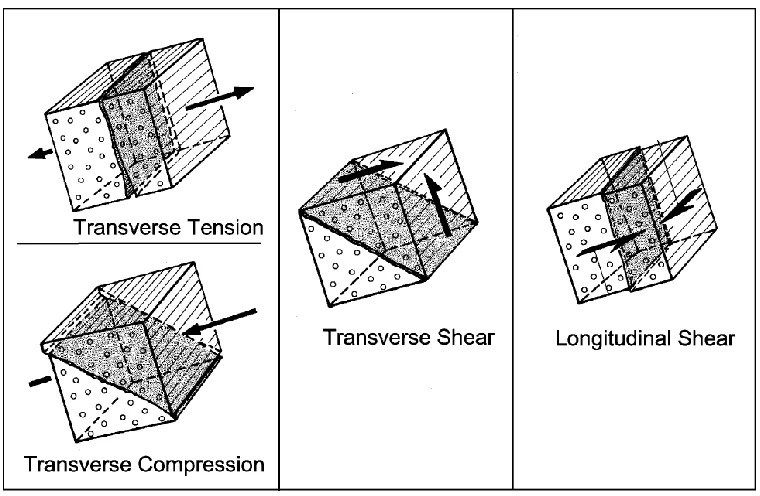
till the fiber boundaries. The IFF can occur in different forms as seen in Figure 3.3 based
on the kind of loading. Under transverse tension or longitudinal shear, a straight crack
oriented perpendicular to the stress is observed while under transverse compression and
transverse shear, an inclined crack is observed. The presence of IFF leads to a redistribution
of stresses in the laminate but the lamina is still able to carry some load. The presence of
IFF leads to successive damage due to a concentration of the stresses and to delamination,
Figure 3.3 Different forms of Inter Fiber Fracture (IFF)
An IFF can have a varying impact on the capacity of a laminate depending on the
angle of the fracture plane. The straight cracks formed under transverse tension or
longitudinal shear can generally be tolerated. The major risk with this type of damage is
the growth of delamination at the crack tips and the damage accumulation due to stress
concentrations around the crack. On the other hand, the inclined fracture angle under
transverse compression and transverse shear loadings are usually destructive for the
laminate. It leads to high instantaneous delamination’s and even the splitting of the
laminate and may lead to the wedge effect.
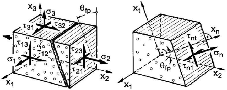
The Puck failure theory determines the angle of the fracture plane and uses the
stresses acting on this plane to determine IFF. It is based on the formulations of Coulumb
and Mohr. The Mohr hypothesis states that the fracture limit of a material is determined by
the stresses acting on the fracture plane. This was originally stated for brittle isotropic
materials. The fracture plane is oriented parallel to the fiber direction and at an angle Ɵ to
the thickness direction. The stresses acting on this action plane σn, 𝜏n1 and 𝜏nt are used to
determine the IFF. The shear stresses 𝜏n1 and 𝜏nt can be combined to form the shear stress
𝜏nψ.
Figure 3.4 Stresses acting on the fracture plane
These stresses are obtained from transforming the σ2, σ3, 𝜏21, 𝜏31 and 𝜏23 stresses as
seen from the following:
{ 𝜎𝑛(𝜃) 𝜏𝑛𝑡(𝜃) 𝜏𝑛1(𝜃)
} = [
𝑐2 𝑠2 2𝑠𝑐 0 0 −𝑠𝑐 𝑠𝑐
0 0 (𝑐
2− 𝑠2) 0 0
0 𝑠 𝑐 ] { 𝜎22 𝜎33 𝜏23 𝜏31 𝜏21}
(3.5)
Where,
𝑐 = 𝑐𝑜𝑠𝜃 𝑎𝑛𝑑 𝑠 = 𝑠𝑖𝑛𝜃
The Puck IFF criterion can be written as follows:
For 𝜎𝑛 ≥ 0:
𝑓𝐸 (𝜃) = √[( 1 −𝑝⊥𝜓 𝑡 ) 𝜎𝑛(𝜃)] 2
+ (𝜏𝑛𝑡(𝜃))2+ (𝜏𝑛1(𝜃)) 2
+𝑝⊥𝜓 𝑡
For 𝜎𝑛 < 0:
𝑓𝐸𝐼𝐹𝐹(𝜃) = √(𝜏𝑛𝑡(𝜃) 𝑅⊥⊥𝐴 )
2
+ (𝜏𝑛1(𝜃) 𝑅⊥∥𝐴 ) 2 + (𝑝⊥𝜓 𝑐 𝑅⊥𝜓𝐴 𝜎𝑛(𝜃)) 2 +𝑝⊥𝜓 𝑐
𝑅⊥𝜓𝐴 𝜎𝑛(𝜃) (1.7)
Where,
𝑝⊥𝜓𝑡,𝑐 𝑅⊥𝜓𝐴 =
𝑝⊥⊥𝑡,𝑐 𝑅⊥⊥𝐴 cos
2𝜓 +𝑝⊥∥ 𝑡,𝑐
𝑅⊥∥𝐴 sin 2𝜓
cos2𝜓 = 1 − sin2𝜓 = 𝜏𝑛𝑡 2
𝜏𝑛𝑡2 + 𝜏 𝑛12
𝑅⊥⊥𝐴 = 𝑅⊥ 𝑐
2(1 + 𝑝⊥⊥𝑐 )
𝑅⊥𝐴𝑡𝑎𝑛𝑑 𝑅⊥∥𝐴 are the tensile strength perpendicular to fiber direction and the in-plane
shear strength respectively,𝑅⊥⊥𝐴 is the fracture resistance due to transverse/transverse shear
stressing. 𝜃𝑓𝑝 is the angle of the fracture plane and 𝑝⊥∥𝑡,𝑐, 𝑝⊥⊥𝑡,𝑐 are inclination parameters.
𝑓𝐸𝐼𝐹𝐹 is the failure effort or stress exposure of the inter fiber failure of the lamina. When
the value of 𝑓𝐸 = 1 is reached, it is termed as the fracture condition of the lamina.
If σn is a tensile stress it promotes IFF by assisting the shear stresses but if σn is a
compressive stress it delays IFF by raising the fracture resistances against shear fracture.
Therefore, separate equations are used to evaluate IFF under tensile and compressive σn
[8].
The action plane orientated at the angle 𝜃𝑓𝑝 is the fracture plane, this is the angle at
which the highest risk of fracture occurs. This angle is determined by calculating 𝑓𝐸𝐼𝐹𝐹(𝜃)
for all planes with angles ranging from 𝜃 = −90° to 𝜃 = 90° with 1° steps, and the plane
with the largest stress exposure is the plane where fracture is to be expected.
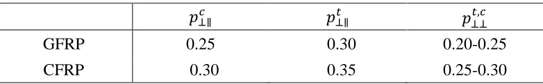
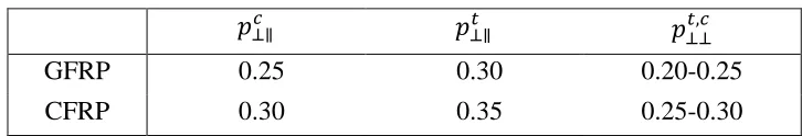
The inclination parameters 𝑝⊥∥𝑡,𝑐, 𝑝⊥⊥𝑡,𝑐 are obtained from the (σ22,𝜏21) curves.
However, it is difficult to obtain these parameters without doing a series of experiments to
obtain this and thus Puck provided recommended values for these inclination parameters
as listed below:
Table 3.1: Recommended Values For Inclination Parameters
𝑝⊥∥𝑐 𝑝⊥∥𝑡 𝑝⊥⊥𝑡,𝑐
GFRP 0.25 0.30 0.20-0.25
3.3 LIST OF REFERENCES
[1] Puck, A.: Festigkeitsberechnung an Glasfaser Kunststoff Laminaten bei zusammen gesetzter Beanspruchung;Bruchhypothesen und schichtenweise Bruchanalyse (Strength analysis on GRP-laminates under combined stresses; fracture hypotheses and
layer-by-layer fracture analysis), Kunststoffe, German Plastics 59 (bilingual edition English and German), (1969), pp 18–19, German text 780–787
[2] Puck A.: Progress in Composite Component Design through Advanced Failure Models. Proceedings of the 17th SAMPE Europe Conference; Basel, Switzerland, 1996, pp. 83–96
[3]Puck, A. and Schürmann, H.: Failure analysis of FRP laminates by means of physically based phenomenological models. Part A; Composites Science and Technology 58 (1998) 7, pp. 1045–1067
[4] Puck, A., Kopp, J. and Knops, M.: Guidelines for the determination of the parameters in Puck’s action plane strength criterion. Composites Science and Technology 62 (2002) 3, pp. 371–378 and 9, p. 1275
[5] VDI 2014/3. Development of Fibre-Reinforced Plastics components: Analysis. Technical report, Verein Deutscher Ingenieure e.V., Dusseldorf, 2006.
[6] H. Matthias Deuschle. 3D Failure Analysis of UD Fibre Reinforced Composites: Puck’s Theory within FEA. Thesis, Faculty of Aerospace Engineering and Geodesy of the Universitat Stuttgart
[7] A. Puck, J. Kopp, and M. Knops. Guidelines for the determination of the parameters in Puck’s action plane strength criterion. Composites Science and Technology, 62(3 & 9):371–378 & 1275, 2002.
CHAPTER 4
PROGRESSIVE FAILURE ANALYSIS OF A COMPOSITE LAMINA
4.1 ABSTRACT
This paper focuses on the progressive failure analysis of a composite at lamina scale
using two different material property degradation models in an open hole specimen under
uniaxial tension. Puck failure criterion is selected to detect the onset of damage. The
ABAQUS user defined material subroutine UMAT was developed to apply the failure
criteria and degradation models. A partial discount method and a gradual stiffness
degradation is implemented in ABAQUS environment. The damage initiation and
progression obtained from the proposed model is compared with the observed experimental
results from digital image correlation. The comparative study confirmed that the simulation
results were in good agreement with the experimental results.
Keywords: Progressive failure analysis, Stiffness Degradation, Puck failure
criteria, DIC
4.2 INTRODUCTION
Fiber-reinforced composites have been established as competitive materials for naval,
automotive and aerospace industry during the last few decades. Their high strength to low
weight ratio attracts a lot of attention to applying it in different industries. Therefore, it is
important to understand the deformation behavior and failure mechanisms of these of
materials under mechanical loading. An imperative part of material behavior is the concept of
damage. Most of the current failure criteria are developed at the lamina scale and hence it is
necessary to see the effect of damage in this scale. A good understanding of initiation and
propagation of damage in composites will help to predict the strength of the structure at a
propagation at the laminate scale; however little work has been carried out explicitly at the
lamina scale.
There are a lot of failure criteria that have been developed over the past few
decades. The most general failure criterion for composite materials is the Tensor
Polynomial Criterion proposed by Tsai and Wu [1]. The other popular and well known
failure criteria include those proposed by Tsai-Hill [2], Azzi-Tsai [3], Hoffman [4] and
Chamis [5]. These criterions do not consider the heterogeneous nature of a lamina and do
not provide the type of failure. The other type of failure criteria which considers the
non-homogeneous characteristics of the composites can be used to differentiate the failure
modes in the material. Hart Smith proposed a generalized Tresca model which considers
fiber shearing as a dominant failure mode [6]. Hashin-Rotem proposed a criterion that
involves two failure mechanisms, one associated with fiber failure and the other with
matrix failure, distinguishing between tension and compression [7].
There are other failure criteria including those by, S C Tan and R J Nuismer who
proposed a progressive matrix cracking model in which the laminate is assumed to contain
periodic cracks with even spacing [8]. H A Whitworth proposed a model to predict the
stiffness degradation in composite laminates based on an assumed relation between the
failure stiffness and the applied stress [9]. Yamada and Sun proposed a criterion
considering the in situ shear strength coupled with the probabilistic nature of composite
failure [10]. R. M. Christensen proposed a criterion where micromechanics was used to
distinguish failure modes [11].
inter-fiber failure(IFF) was differentiated into three including the transverse tension (mode
A), moderate transverse compression (mode B), and large transverse compression (mode
C). Also, an equation was proposed to determine the angle of the fracture plane [12]. Both
the Hashin and the Puck and Schürmann criteria were 2D criteria ignoring interlaminar
stresses.
Later, Puck modified his criteria to include interlaminar stresses. The new failure
criteria was termed as action-plane failure criteria wherein IFF was calculated based on
stresses which act on planes parallel to the fiber and inclined at an angle θ with respect to
the thickness direction [13].
The Verein Deutscher Ingenieure (VDI) provides a detailed description of the
concepts and design of composites and the analysis using the Puck failure criteria and are
incorporated in this work [14].
Once the damage is found to initiate by the failure criteria, the material properties
are degraded to simulate the presence of cracks in the material. One of the popular and
simple method is the Total Discount Method [15] wherein the stiffness are reduced to zero
in the failed ply. Further work on stiffness reduction has been developed by Nahas [16]
and Soden [17] among others. In the current work, a partial discount method [18] and a
gradual stiffness reduction method [12-13] are utilized to model the degradation.
In order to validate the Puck damage prediction model, the evolution of damage in
a specimen must be observed. One approach is to utilize a non-destructive technique that
will allow for the detection of damage evolution in a composite structure such as digital
image correlation (DIC). In our work experiments are conducted with the help of DIC
4.3 THEORY
4.3.1 CONSTITUTIVE RELATION
The constitutive models in a quasi-static stress analysis relates the state of strain to the state
of stress. The material is considered as linear elastic and transversely orthotropic. The
linear elastic stress–strain constitutive relation can be written as follows:
{ϵ} = [S]{σ} or {σ} = [C]{ϵ} (4.1)
C11 = E11(1 − v23v32)∆ (4.2)
C22 = E22(1 − v13v31)∆ (4.3)
C33= E33(1 − v12v21)∆ (4.4)
C12= E11(v21− v31v23)∆ (4.5)
C13= E22(v32− v12v31)∆ (4.6)
C23= E33(v31− v21v32)∆ (4.7)
∆= 1 1 − v⁄ 12v21− v23v32− v31v13− 2v21v32v13 (4.8)
{ σ11 σ22 σ33 σ12 σ13 σ23}
=
[
C11 C12 C13 C12 C22 C23 C13 C23 C33
0 0 0 0 0 0 0 0 0 0 0 0
0 0 0 0 0 0
2G12 0 0
0 2G13 0
0 0 2G23]{ ϵ11 ϵ22 ϵ33 ϵ12 ϵ13 ϵ23}
(4.9)
Where Cij are the material stiffness tensors vij are the Poisson ratio, Eij are the Young’s
moduli and Gij are the shear moduli
4.3.2 PUCK FAILURE THEORY
Puck’s criteria for fiber fracture (FF) and inter-fiber fracture (IFF) of unidirectional
are particularly important, which have been developed for quasi-isotropic materials. They
have been adapted by Puck to the transversely orthotropic UD fiber/polymer composites.
The action-plane fracture criteria is formulated using stresses σn, 𝛕nt and 𝛕n1
instead of σ11, σ22, σ33, 𝛕12, 𝛕13, 𝛕23, which act on a plane parallel to the fibers and at
an angle θ. These stresses are calculated with the aid of the following transformation:
{ 𝜎𝑛(𝜃) 𝜏𝑛𝑡(𝜃) 𝜏𝑛1(𝜃)
} = [
𝑐2 𝑠2 2𝑠𝑐 0 0 −𝑠𝑐 𝑠𝑐
0 0 (𝑐
2 − 𝑠2) 0 0
0 𝑠 𝑐 ] { 𝜎22 𝜎33 𝜏23 𝜏31 𝜏21}
(4.10)
Where,
c=cosθ and s=sinθ
In order to characterize certain types of stress, Puck introduces the concept of
‘stressing’ [22], differentiating stresses into acting transverse (⊥) to the fiber direction or
parallel ( || ) to the fiber direction.
The Puck failure criterion can be written as follows:
fEFF = 1
±R∥t,c[σ11− (v⊥∥− v⊥∥f. mσf E∥
E∥f) (σ22+ σ33)] (4.11)
𝑤𝑖𝑡ℎ {+𝑅∥
𝑡 𝑓𝑜𝑟 [… ] ≥ 0
−𝑅∥𝑐 𝑓𝑜𝑟 [… ] ≤ 0
For 𝜎𝑛 ≥ 0:
fEIFF(θ) = √[(
1 R⊥At−
p⊥ψt
R⊥A ψ
) σn(θ)] 2
+ (τnt(θ) R⊥⊥A
) 2
+ (τn1(θ) R⊥∥A )
2 +p⊥ψ
t
RA⊥ψ
For 𝜎𝑛 < 0:
fEIFF(θ) = √(τnt(θ) RA⊥⊥ )
2
+ (τn1(θ) R⊥∥A )
2
+ (p⊥ψ c
RA ⊥ψσn(θ)) 2
+ p⊥ψ c
RA⊥ψσn(θ)
(4.13)
Where,
𝑝⊥𝜓𝑡,𝑐 𝑅⊥𝜓𝐴 =
𝑝⊥⊥𝑡,𝑐
𝑅⊥⊥𝐴 cos2𝜓 + 𝑝⊥∥𝑡,𝑐
𝑅⊥∥𝐴 sin2𝜓
cos2𝜓 = 1 − sin2𝜓 = 𝜏𝑛𝑡 2
𝜏𝑛𝑡2 + 𝜏 𝑛12
𝑅⊥⊥𝐴 = 𝑅⊥ 𝑐
2(1 + 𝑝⊥⊥𝑐 )
Where, σ11, σ22 and σ33 are normal stresses in the lamina, ±𝑅∥𝑡,𝑐are the tensile and
compressive strengths parallel to fiber direction, 𝑣⊥∥𝑓 is the fiber volume fraction, 𝑚𝜎𝑓 is the
stress magnification factor, 𝐸∥𝑓 is the Young’s modulus of the fiber along the fiber direction,
𝑅⊥𝐴𝑡 is the tensile strength perpendicular to fiber direction, 𝑅⊥∥𝐴 is the in-plane shear
strength, 𝑅⊥⊥𝐴 is the resistance offered against fracture due to transverse/ transverse shear
stressing, 𝜃𝑓𝑝 is the angle of the fracture plane and 𝑝⊥∥𝑡,𝑐, 𝑝⊥⊥𝑡,𝑐are inclination parameters
obtained from the (𝛕n1, σn) and (𝛕nt, σn) fracture curves respectively. 𝑓𝐸is called the stress
exposure and it is the ratio between the length of the vector of the stresses{σ} and the length
of the corresponding fracture vector{σ}fr which have the same direction. When 𝑓𝐸 = 1 , it is
If σn is a tensile stress it assists the shear stresses in causing IFF, and if σn is a
compressive stress it delays IFF due to the shear stresses. Therefore, separate equations are
used to evaluate IFF [23].
The stress exposure 𝑓𝐸𝐼𝐹𝐹(𝜃𝑓𝑝) is dependent on the angle of the fracture plane 𝜃. This
angle is determined by calculating 𝑓𝐸𝐼𝐹𝐹(𝜃) for angles ranging from 𝜃 = −90° to 𝜃 = 90°,
and the plane with the largest stress exposure is the plane where fracture is to be expected.
[fEIFF(θ)]max= fEIFF(θfp) (4.14)
The angle of the fracture plane is important in assessing failure, for example
θ_fp≈90° indicates a high probability of delamination, if θ_fp>30° and σ_n<0 it indicates
Mode C failure. The fracture plane in the mode C is different and it would be destructive
for the laminate. One surface of the crack slides over the other surface of crack causing the
local delamination or buckling of neighbors called the wedge effect [14].
The values of the inclination parameters recommended by Puck are used in the
current work as shown in Table 4.1 [24].
Table 4.1: Recommended values for inclination parameters
4.3.3 MATERIAL PROPERTIES DEGRADATION
As the damage identified in the composite material, the appropriate approach
should be applied to assess the damage growth until failure. Two methods have been
compared for the material degradation after the damage was initiated. The first method is
called element weakening method which is a partial discount method [19]. The second
𝑝⊥∥𝑐 𝑝⊥∥𝑡 𝑝⊥⊥𝑡,𝑐
GFRP 0.25 0.30 0.20-0.25
method is the constant stress exposure method which is a gradual stiffness reduction
method [12-13]. These degradation methods are defined in a smeared crack approach,
wherein the degradation process is assumed as the growth of the crack density.
4.3.3.1 ELEMENT WEAKENING METHOD (EWM)
In this method, selected elastic properties of elements are degraded to zero when
the stress exposure reaches a value of one. The modulus perpendicular to fibers and inplane
shear modulus are degraded for IFF and all of the elastic properties are degraded in case of
a FF. However, as this causes convergence issues in the FE software the values are instead
degraded to a value close to zero. Depending on the failure mode the values of the damage
variables are updated. For fiber failure under tension dft=1, under compression dfc=1; for
matrix failure, due to σ_n>0, dmt=1, due to σ_n<0, dmc=1. The degradation rule for EWM
used is as listed below:
𝑑𝑓 = (1 − 𝑑𝑓𝑡)(1 − 𝑑𝑓𝑐) (4.15)
𝑑𝑚 = (1 − 𝑑𝑚𝑡)(1 − 𝑑𝑚𝑐) (4.2)
𝐶11′ = (1 − 𝑑𝑓)𝐶11 (4.3)
𝐶22′ = (1 − 𝑑𝑓)(1 − 𝑑𝑚)𝐶22 (4.18)
𝐶33′ = (1 − 𝑑
𝑓)(1 − 𝑑𝑚)𝐶33 (4.19)
𝐶12′ = (1 − 𝑑
𝑓)(1 − 𝑑𝑚)𝐶12 (4.20)
𝐶13′ = (1 − 𝑑𝑓)(1 − 𝑑𝑚)𝐶13 (4.21)
𝐶23′ = (1 − 𝑑𝑓)(1 − 𝑑𝑚)𝐶23 (4.22)
𝐺12′ = (1 − 𝑑𝑓)(1 − 𝑑𝑚𝑐𝑠𝑚𝑐)(1 − 𝑠𝑚𝑡𝑑𝑚𝑡)𝐺12 (4.23)
𝐺31′ = (1 − 𝑑𝑓)(1 − 𝑑𝑚𝑐𝑠𝑚𝑐)(1 − 𝑠𝑚𝑡𝑑𝑚𝑡)𝐺31 (4.25)
Where df and dm are the total damage variables for the fiber and matrix respectively;
dft, dfc, dmt, and dmc are the fiber and matrix damage variables in relation to the tensile and
compressive stress states, respectively; and smt and smc are the loss control factors for the
shear stiffness caused by the matrix tensile and compressive failures, respectively. In the
present study, the loss control factors were set as smt = 0.9 and smc = 0.5.
4.3.3.2 CONSTANT STRESS EXPOSURE METHOD (CSE)
The gradual stiffness reduction method is based on the stress exposure 𝑓𝐸. In this
method when fiber failure occurs all the stiffness’ are degraded like the EWM approach
and only the stiffness due to IFF are gradually reduced. This approach conserves the
meaning of the value 𝑓𝐸𝐼𝐹𝐹 = 1 as a fracture criterion, i.e. the lamina does not experience
an IFF stress exposure above 1. When the stress exposure of a lamina reaches this value an
IFF occurs and the lamina gets rid of parts of its load by redistribution. This is
accomplished by incrementally degrading the stiffness based on the mode of damage to a
value such that 𝑓𝐸𝐼𝐹𝐹 will be equal to 1. The stiffness Ei and Gij are degraded unequally
[23]. The progressive damage rule for CSE is:
E2red = {E2 orig
. (1 − dmt) for σn> 0
E2orig for σn < 0
(4)
G12red = G12orig. (1 − k. dmt)(1 − k. dmc) (4.27)
4.4 ANALYSIS
4.4.1 EXPERIMENTAL SETUP
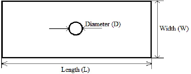
A single zero-degree lamina with a central hole was used with dimensions given in Table
4.2 and configurations as shown in Figure 1. The specimen was loaded in uniaxial tension
using an MTS810 machine with a loading rate of 0.05”/min. The material properties are
listed in Table 4.3. DIC was used to capture the far-field global strain data. A 5MP camera
with a 60mm Nikon lens was used to capture the gradual deformation of the speckled
lamina during loading. A white light illumination is used to illuminate the speckled surface.
The load at failure was determined to be 2805N.
Table 4.2: Dimensions of the Test Specimen
Length Width Thickness Diameter of notch
200 25 0.22 4
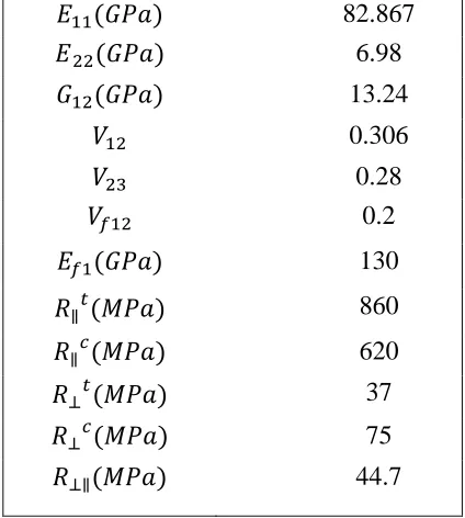
Table 4.3: Material Properties Of Test Specimen
𝐸11(𝐺𝑃𝑎) 82.867
𝐸22(𝐺𝑃𝑎) 6.98
𝐺12(𝐺𝑃𝑎) 13.24
𝑉12 0.306
𝑉23 0.28
𝑉𝑓12 0.2
𝐸𝑓1(𝐺𝑃𝑎) 130
𝑅∥𝑡(𝑀𝑃𝑎) 860
𝑅∥𝑐(𝑀𝑃𝑎) 620
𝑅⊥𝑡(𝑀𝑃𝑎) 37
𝑅⊥𝑐(𝑀𝑃𝑎) 75
Figure 4.1 Test specimen Configuration.
4.4.2 COMPUTATIONAL ANALYSIS PROCESS
The commercial FEA software, ABAQUS was employed to simulate the model by
using a user defined material behavior (UMAT subroutine). The composite was modeled
with a load of 3000N being applied at one end and encastre boundary condition at the other
end. Three-dimensional hexahedral element (C3D8R) was selected for FE simulation with
a total of 15082 elements in the model. A small time step is used to help reduce
nonlinearities in each step and hence improve the convergence.
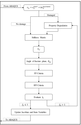
Figures 2 shows the algorithm for the two degradation models used. This procedure
is carried out at all material calculation points of elements for each increment. The initial
strain and the incremental strain are received from ABAQUS along with the material
properties. If damage is noted at the point the elastic properties are appropriately degraded.
After which the stiffness matrix and the resulting stresses are calculated and then used as
input parameters for the Puck theory to detect damage. If the fracture condition is met,
material properties are degraded and this process continues until f_E≤1 or the maximum
degradation is reached. After this, the Jacobian and state variables are updated and these
= 𝑡𝑎 𝑡+ 𝑛𝑐 𝑚 𝑛𝑡
Stiffness Matrix
Property Degradation
𝜎
Angle of fracture plane, 𝜃𝑓𝑝
From ABAQUS
FF Criteria
IFF Criteria
Evaluate fE
Update Jacobian and State Variables
To ABAQUS
Damaged
𝑓𝐸> 1 𝑓𝐸≤ 1
No damage
Figure 4.2 Algorithm for ABAQUS subroutine
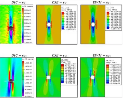
4.4.3 RESULTS AND DISCUSSION
The strain distribution from DIC and FEM are shown in Figure 3. The strains from
the FEM are compared with the DIC a few steps before failure at a load of 2508N. A line
of elements around the hole are concealed from the FE results to match the DIC condition.
for the CSE method. The EWM method shows much higher strains as fiber failure is
detected at a previous load state.
Figure 4.3 Experimental and Finite Element strain distribution at 2508N.
The results of the progressive damage from Puck criteria using the element
weakening and constant stress exposure methods at increasing loading states are shown in
Figure 4 and Figure 5 respectively. Initial matrix damage was observed at a load of 507.2N
due to σ_n under tension. The matrix damage progressively increases tangential to the hole
along the fiber direction in both the models. The contour of the damage due to EWM
spreads more than the damage in the CSE. The partial discount degradation of EWM causes
more elements to fail at a faster rate than the gradual degradation of CSE as the stiffness
assumed at the first fiber breakage. For EWM fiber failure occurs at 2455N (12.4% error)
while for CSE fiber failure occurs at 2637N (5.9%). Both the methods underpredicted the
failure load but are within a reasonable limit.
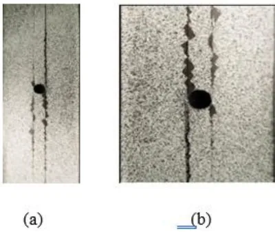
From these results, it can be perceived that matrix cracks occur in the sample and
once fiber failure occurs the crack propagates along the damaged matrix. The damage from
the experimental results can be seen in Figure 6. Both the models show good agreement
with the experimental results. The CSE method provides more accurate strain correlation
with the DIC.
Figure 4.4 Matrix damage propagation at different load steps using EWM.
Figure 4.6 Image taken after failure of 0-degree specimen (b) close-up of specimen.
4.5 CONCLUSION
In the current study, the Puck failure criteria is used to predict the initiation and
propagation of damage in 0 degree CFRP lamina using two degradation methods. The
failure criterion and degradation models are implemented in ABAQUS using a UMAT
subroutine. The FEA results are in good agreement with the experimental results. The
gradual degradation method is found to be better at predicting failure of the composite
specimen with an error of 5.9%. However, CSE is computationally more expensive as it
requires to find the amount by which to degrade the element when an IFF occurs whereas
EWM directly degrades the material to the maximum degradation. The Puck criteria is a
robust criterion which can be employed as a to estimate damage initiation and progression
4.6 LIST OF REFERENCES
[1]. Tsai, S. W., and Wu, E. M., A General Theory of Strength for Anisotropic Materials, Journal of Composite Materials, 5, 58-80, 1971 2-
[2]. Tsai, S.W., “Strength Characteristics of Composite Materials”, NASA CR-224, 1965.
[3]. Azzi, V.D. & Tsai, S.W., “Anisotropic Strength of Composites”, Experimental Mechanics, September 1965, pp. 283-288.
[4]. Hoffman, O., “The Brittle Strength of Orthotropic Materials”, J. Composite Materials, v. 1, 1967, pp. 200-206.
[5]. Chamis, C.C., “Failure Criteria for Filamentary Composites”, Composite Materials: Testing and Design, STP 460, ASTM, Philadelphia, 1969, pp. 336-351.
[6]. Hart-Smith, L. J. "Predictions of the original and truncated maximum-strain failure models for certain fibrous composite laminates - Chapter 3.5."
[7]. Hashin, Z. & Rotem, A., “A Fatigue Failure Criterion for Fibre Reinforced Materials”, J. Composite Materials, v. 7, 1973, pp. 448-464.
[8]. Nuismer, R. J. and Tan, S. C., "Constitutive Relations of a Cracked Composite Lamina", Journal of Composite Materials, 22, 306-321, 1988
[9]. Whitworth, H. A. "Modeling stiffness reduction of graphite/epoxy composite laminates." Journal of Composite Materials 21.4 (1987): 362-372.
[10]. Yamada, S. E. and Sun, C. T., "Analysis of Laminate Strength and its Distribution", Journal of Composite Materials, 12, 275-284, 1978
[11]. Cristensen RM. Stress based yield/failure criteria for fiber composites. 12th International Conference on Composite Materials. 1999; Paris, France. Paris: 1999.
[12]. A Puck and H Schürmann, ‘Failure analysis of FRP laminates by means of physically based phenomenological models’, Compos Sci Techno, V58, pp 1045–1068, 1998.
[13]. A Puck and H Schürmann, ‘Failure analysis of FRP laminates by means of physically based phenomenological models- Part B’, Compos Sci Techno, V62, pp 11633– 1672, 2002
[15]. C T Sun and J X Tao, ‘Prediction of failure envelopes and stress-strain behaviors of composite laminates’, Compos Sci Techno, V58, pp 1125–1136, 1998,
[16]. Nahas, Mahmoud N. "Survey of failure and post-failure theories of laminated fiber-reinforced composites." Journal of Composites, Technology and Research 8.4 (1986): 138-153.
[17]. Soden PD, Hinton MJ, Kaddour AS (1998) A comparison of the predictive capabilities of current failure theories for composite laminates. Composites Science and Technology 58: 1225–1254
[18]. Lee, Chi-Seung, et al. "Initial and progressive failure analyses for composite laminates using Puck failure criterion and damage-coupled finite element method." Composite Structures 121 (2015): 406-419.
[19]. C.A. Coulomb. Sur une Application des R`egles de Maximis et Minimis a quelques Problemes de Statique relatives a l’Architecture. In Memoires de Mathematique et de Physique: Ann´e 1773. Academie Royal des Sciences par divers Savans, Paris, France, 1776.
[20]. O. Mohr. Welche Umst¨ande bedingen die Elastizit¨atsgrenze und den Bruch eines Materials. Zeitschrift des VDI, 24(45/46):1524–1541 & 1572–1577, 1900.
[21]. B. Paul. A Modification of the Coulomb-Mohr Theory of Fracture. Journal of Applied Mechanics, 28:259–268, 1961.
[22]. Lutz, Gunther. "The Puck theory of failure in laminates in the context of the new guideline VDI 2014 Part 3." Conference on damage in composite materials. 2006.
[23]. H. Matthias Deuschle. 3D Failure Analysis of UD Fibre Reinforced Composites: Puck’s Theory within FEA. Thesis, Faculty of Aerospace Engineering and Geodesy of the Universitat Stuttgart
CHAPTER 5
PROGRESSIVE FAILURE ANALYSIS OF A COMPOSITE