R E S E A R C H
Open Access
Increased diversity space-time coding using
the diversity transform
Amir J Salomon
*and Ofer Amrani
*Abstract
The paper presents a method for constructing space-time block codes for multiple-input multiple-output channels by concatenating orthogonal designs with the so-calleddiversity transform. Relying on unitary transforms, the diversity transform increases the channel alphabet without sacrificing information rate, bandwidth, or Euclidean distance. The distribution of the resulting channel alphabet is shown to quickly become Gaussian-like. Specific code matrices are constructed and optimized based on the cutoff rate. Both optimum and, reduced-complexity, suboptimum detection algorithms are presented. Simulation results are provided for demonstrating the gains attainable when using the proposed codes.
Keywords: Space-time coding; Error correcting codes; Diversity; Wireless channels
1 Introduction
Wireless channels often suffer from severe signal atten-uation due to multipath propagation. Consequently, the receiver faces greater difficulty in determining the trans-mitted signal reliably unless some less attenuated replica of the signal is somehow available. This serves as the basis for an approach, generally known as diversity, which is achievable via temporal, frequency, polarization, or spa-tial resources. In some applications, practical means of achieving diversity is by deploying multi-element antenna arrays at the transmitter and/or receiver side.
Alamouti [1] presented an effective communication scheme employing two transmit antennas jointly with a simple detection procedure. Space-time (ST) block codes, introduced by Tarokh et al. [2], generalize Alamouti’s scheme for an arbitrary number of transmit antennas. These codes exploit the theory of orthogonal designs and achieve the full diversity attainable with any configuration of transmit and receive antennas.
Providing time diversity via classical coding techniques typically entails frequency expansion. There are various solutions to this problem - most relevant to the current work include high diversity lattices, see, e.g., [3,4] and the references therein, and the so-called diversity trans-form(DRT) [5,6]. The diversity transform increases the
*Correspondence: [email protected] ; [email protected]
Department of Electrical Engineering-Systems Ramat Aviv, Tel Aviv University, Tel-Aviv 69978, Israel
channel alphabet, and hence the diversity, by employing appropriate unitary matrix multiplication.
The code construction presented herein is aimed at combining the properties of the two aforementioned approaches in a manner that facilitates computationally efficient encoding and detection. The resulting codes may be considered as multi-layered space-time codes, whereby coding based on orthogonal designs is applied to each layer, and where the different layers are linearly depen-dent via some unitary transformation. This multi-layered structure improves the diversity without sacrificing band-width, while producing channel alphabet whose distri-bution quickly becomes Gaussian-like (the distridistri-bution appears as sampled Gaussian function with a number of samples proportional to the dimension of the DRT and the constellation used).
For notational brevity, we shall henceforth refer to the obtained serially concatenated codes asdiversified space-time(DST) codes.
DST codes provide high degree of flexibility in adapt-ing the code parameters to any antenna configuration and channel coherence time, which, in turn, determines the size of the diversity transform to be employed. A DST code can be very short, as short as two code words of the constituent ST code. Thus, it may introduce very small detection delay, while still providing high performance gain, compared to the constituent ST codes, with low
encoding and detection complexity. In general, implemen-tation complexity is only slightly higher than that of the constituent ST code. This is compared to constructions which have promising information theoretic properties [7], but their detection is typically hard to realize.
A different interesting approach for serially concatenat-ing ST codes with rate-1 codes was introduced before. Therein, Lin and Blum [8] employed a rate 1 recursive code, with feedback polynomial (1 + D). ST coding is used as the outer code, and so the obtained alphabet con-sists of the symbols of the constellation used, which is typically quadrature amplitude modulation (QAM). This concatenation approach along with the suggested iterative detection scheme [8] is mentioned to be more suitable for applications which can tolerate some delay.
While coding schemes that use rotation transforma-tion within a codeword are known, see, e.g., the seminal work of Boutros and Viterbo [9], herein, we attempt to construct and optimize a transform that operates concur-rently on a plurality of codewords of a known scheme with minimum added detection complexity.
The rest of the paper is organized as follows. Back-ground material and definitions are given in Section 2. The proposed DST code construction is presented in Section 3 along with analysis of the code’s alphabet dis-tribution. DRT matrices are constructed and optimized based on the cutoff rate in Section 4. The optimization is carried out assuming that the average received SNR is known to the transmitter while channel state information (CSI) is required only at the receiver side. In Section 5, a two-stage suboptimum detection algorithm is presented based on linear estimation. Optimum detection is also briefly mentioned. Section 6 provides simulation results for a rich set of scenarios and DST codes of bandwidth efficiencies 1, 2, and 3 bits/s/Hz. Finally, conclusions are drawn in Section 7.
2 Background
2.1 The channel model
We consider a wireless communication system where the transmitter is equipped withnantennas and the receiver withmantennas. At each time slott, complex symbolsyti, i=1, 2,. . .,n, are transmitted simultaneously from then transmit antennas. We denote byhti,j the path gain from transmit antennaito receive antennajat time slott. The different paths are assumed frequency-nonselective, and their gains are modeled as samples of independent com-plex Gaussian random variables with variance 12 per real dimension. The channel is of block-fading type, meaning that the path gainshti,jare constant over several time slots to which we refer as ablock. The path gains are assumed statistically independent among different blocks. A single DST codeword, or code array as it will be called in the sequel, spans over several channel realizations.
At timet, the valuerjt, received at antennaj, is given by:
rjt= n
i=1
hti,jyti+ηjt (1)
where the noise samplesηtj are independent samples of a zero-mean complex Gaussian random variable with vari-ancen/(2SNR) ≡ σ2/2 per real dimension. The average energy of the symbols transmitted from each antenna is normalized to be one, so that the average power of the received signal at each receive antenna isnand the signal-to-noise ratio is SNR.
2.2 Codes from orthogonal designs 2.2.1 Code construction
Space-time block codes constructed from orthogonal designs were introduced by Tarokh et al. [2] as a general-ization of the so-called Alamouti scheme [1]. A space-time code is defined as a p× ntransmission matrix G with orthogonal columns. The entries of the matrixGare linear combinations of the complex variablesx1,x2,. . .,xk and their conjugates; these variables are actually the source (data) symbols to be transmitted. Since ptime slots are allocated for transmittingk symbols, the symbol rate of the code isR=k/p.
For example,G2is the Alamouti code for two transmit antennas; it has rateR=1 (asp=k=n=2):
G2=
x1 x2 −x∗2 x∗1
. (2)
Other codes that will be used in this work are the rate half codes,G3andG4, and rate 3/4 codesH3andH4, given in Appendix.
2.2.2 Conventional detection scheme
For completeness, we briefly review the detection pro-cess used for the abovementioned ST codes. The symbols x1,x2,. . .,xk can be detected at the receiver via linear processing. As an example, for the codeG2, the receiver constructs the next two values:
˜
x1=
m
j=1
(h∗1,jrj1+h2,j(r2j)∗),
˜
x2=
m
j=1
(h∗2,jr1j −h1,j(r2j)∗). (3)
Plugging Equation 1 into Equation 3, it is easy to derive: ˜
x1 = ˜h·x1 + ˜η1; and x˜2 = ˜h·x2 + ˜η2, whereh˜ =
m
Proposition 1.For any space-time block code constructed from orthogonal design with variables x1,x2,. . .,xk, and assuming perfect knowledge of channel are independent zero mean complex Gaussian random variables with variance σ22 · ˜h per real dimension.
Henceforth, without loss of generality, it is assumed that α =1, since one can divide both sides of Equation 4 byα and obtain the same model (up to the noise variance).
3 Diversified space-time codes
Let Y ∈ CN denote an N-dimensional vector whose entries belong to a complex alphabet of cardinalityM. The diversity transform is a linear operation onYrepresented as
X=AY, (5)
where A is an N × N unitary matrix. This trans-form increases diversity owing to increased alphabet size [5,10]; it preserves the average energy and the minimum Euclidean distance of the input set {Y}. In Subsection 3.3, we show that the output set{X} quickly becomes Gaussian-like (with the increase ofN).
3.1 General coding description
The diversity transform and orthogonal designs, described in Section 2.2, can be combined so as to pro-vide a coding scheme of increased diversity. The proposed scheme employs an N-dimensional diversity transform combined with N space-time codewords, each of rate R= kp.
Letxji, 1≤ j ≤N, 1 ≤ i ≤k, denote the symbolxito be transmitted by thejth ST codeword. Correspondingly, definekvectors of the form
Xi=[x1ixi2. . .xNi]T, (6)
where each of these vectors is obtained by multiplying a (source)N-dimensional vectorYi by the DRT matrixA (5). The second step is to encode theN k-dimensional vec-tors [xj1xj2. . .xjk], 1≤j≤N, intoNST codewords, which constitute a single DST code array.
The proposed coding scheme is best explained by means of an example usingN = 2. In this case, we use DRT of order 2 and two transmit antennas. Denote byY1 = [y11y21]T, Y
2 =[y12y22]T a set of symbols from a given
constellation. First, use the diversity transform matrixA to obtain two so-calleddiversifiedvectors
X1=
Next, two ST codewords are generated:
first ST codeword
and a second ST codeword
The two ST component codewords, which constitute a single DST code array, are transmitted one following the other.
Stated more generally, any orthogonal design code can be represented as ap×nmatrix,nbeing the number of transmit antennas: torYiconsists ofNsymbols, which represent the source information. Using these vectors, we create a group ofk vectorsXi (each of lengthN), created using the diversity transform:
Xi=AYi, (8)
The elements of each vector Xi are denoted by Xi = [x1ix2i . . .xNi ]T.
A DST code array can thus be simply described as a sequence ofNST component codewords in the form:
Symbols from consecutive ST component codewords are interrelated via the diversity matrixA. Note that in prac-tice, these ST component codewords do not have to be transmitted consecutively in time. Rather, some form of interleaving can be applied in order to maximize the diver-sity of the DST code array for the price of somewhat increased decoding latency. A DST code array conveys a total of k·N source symbols usingp·N channel uses, while the component ST orthogonal design code conveys ksource symbols usingpchannel uses, i.e, coding rate of k/psymbols per channel use is preserved.
3.2 Receiver-side description
At the receiver side, the ST codewords are decoded first by employing linear processing in accordance with Propo-sition 1. Thus,k N-dimensional vectorsRi, 1≤i≤k, are obtained each of which is related toXiandYibya
Ri=HXi+i=HAYi+i, (9)
whereHis anN×Ndiagonal matrix given by:
H= from transmit antennaito receive antennajfor ST code-word t, and where i is an N dimensional vector of independent complex Gaussian random variables, i = [η˜1i,η˜2i,. . .,η˜iN]T, withE{i†i} =σ2·H. Detailed descrip-tion of the detecdescrip-tion process is deferred to Secdescrip-tion 5.
3.3 DST codes - alphabet distribution
The DST code construction presented in this section, and particularly the use of high-diversity transforms, results with code alphabet of increased cardinality and non-uniform distribution which tends to approach (discrete) Gaussian even for small transform dimensions.
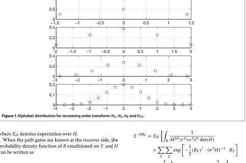
Figure 1 demonstrates the last assertion. The statistical distribution of the elements of X is plotted: Y is cho-sen from BPSK constellation, and normalized Hadamard matrices of increasing order are used as representing the transform matrixA. The convergence to Gaussian distri-bution is evident as the transform order,N, is increased.
TakingNto be asymptotically large, the following prop-erty of the DST construction is simple to prove.
Proposition 2. The DST code output X approaches a Gaussian vector as N→ ∞.
Proof. This proposition follows simply from the central limit theorem.
Proposition 3. IfAis an orthonormal matrix and the components of Y are uniformly, symmetrically distributed around 0 and obeying the power constraint E(y2i) = P, then in the limit N → ∞, the components of X are statis-tically independent, Gaussian distributed with zero mean and variance P.
Proof. E(yi) = 0 due to the symmetrical distribution of Yaround 0; therefore:
E(xi)=E(ai,1y1+ai,2y2+. . .+ai,NyN)=0, used the independence of the components ofY and the orthonormality of matrixA. According to proposition 2, Xapproaches a Gaussian vector asN → ∞; its autocor-relation matrix is diagonal with elementsP; therefore the components ofXare statistically independent, Gaussian distributed with zero mean and varianceP.
The benefit of Gaussian-distributed source alphabet for various communication channels is a well-studied infor-mation theoretic topic.
4 Diversity transform construction and optimization
Diversity transform matrices for DST codes can be opti-mized based on maximizing the mutual information I(R,Y)betweenRandY. Maximization ofI(R,Y), how-ever, turns out to be a complex task [11]. Alternatively, we shall employ the cutoff rate as a measure with respect to which the diversity transform is optimized. The channel cutoff rate R0 is a lower bound on the Shannon channel capacity C. Its usage in place of capacity often leads to tractable results. In this context, the detection is assumed to be maximum likelihood.
4.1 Cutoff rate analysis
Viewing anN-dimensional vectorYas a ‘super’ symbol of an infinite-length (random) code in which all super sym-bols are statistically independent, the cutoff rateR0(N)for single channel use is given by [12]:
−1.50 −1 −0.5 0 0.5 1 1.5
Figure 1Alphabet distribution for increasing order transform:H2,H4,H8andH16.
whereEHdenotes expectation overH.
When the path gains are known at the receiver side, the probability density function ofRconditioned onYandH can be written as
fR(R|Y,H)=
The cutoff rateR0for a single channel usage of each of theNsymbols constitutingYisR0(N)/N, thus combining Equations 11 and 12 one obtains
2−NR0 =E
For notational brevity, we introduce Z as a dummy variable (of the same nature as Y in Equation 13) and defineRY ≡R−HAYandRZ≡R−HAZ; thus, we have
whereIjis defined as
Ij=
where
Gj= | N
i=1aji(Yi−Zi)|2
4 . (16)
According to the channel model used,h˜jare statistically independent among different blocks; Equation 14 then becomes
The following proposition will be useful for the calcula-tion of the expectacalcula-tion in Equacalcula-tion 17:
Proposition 4.h˜j is chi-square distributed with 2mn degrees of freedom, where n and m are the number of transmit and receive antennas, respectively.
Proof.
which is the sum of the squares of 2mn independent, N(0, 0.5)-distributed, random variables. The distribution ofh˜tis therefore
withU(.)being the unit step function.
Combining Proposition 4 with Equation 15 gives
Eh˜j
From Equations 17 and 18, it follows that
R0=log2M−
whereGjis defined in Equation 16. Note that the actual cutoff rate of a scheme which uses an orthogonal design with parametersp,kis multiplied by a factor ofk/p, since
p time slots are used to transmitk symbols; the actual cutoff rate is therefore
R0(p,k)
It is evident from Equation 20 that in order to maximize R0, one has to minimize the term
This, in turn, is achieved by identifying ‘good’ unitary matricesAusing the relation (16), betweenGjandA, such that Equation 21 is minimized. This is the subject of the next subsections.
4.2 Using gradient descent algorithm
Unfortunately, matrices that minimize Equation 21, and hence optimize the cutoff rate, do not admit a closed form solution. In this subsection, we propose a gradient descent-based algorithm for finding a matrix,A, that min-imizes Equation 21. A is typically required to obey the following constraint
n
i,j=1
|aij|2=n, (22)
so that the total average transmitted power remains con-stant. First, denote the complex derivative of the real functionF(A)with respect toakl (the term in rowkand
A single iteration of gradient descent for minimizing Equation 21 is given by
akl(i+1)=akl(i)−δ·F(A)
i.e., each iteration attempts to updateAin a direction that makesF(A)smaller.δis a positive constant which deter-mines the step size in each iteration. The derivative (23) can be calculated from Equation 21 as:
where each iteration of Equation 24 is followed by nor-malization of the matrix A according to Equation 22; this normalization is less acute for convergence of the algorithm when the step sizeδgets smaller.
4.3 Construction of DRT matrices using elementary unitary matrices
An alternative approach for constructing DRT matrices is briefly described herein.
A unitary matrix with determinant equal to one can be constructed as the product of elementary unitary matri-ces with determinant equal to one [13]. An elementary unitary matrix is of the form
Tij=
The elementary unitary matrix Tij has 3 degrees of freedom, and differs from the unit matrix in only four ele-ments, located at the intersection of exactly two rowsi and jwith two columns i and j where i < j. We con-struct unitary matrices with determinant one as a product of12N(N−1)elementaryN-dimensional unitary matrices
A=
4.4 Transform optimization - results
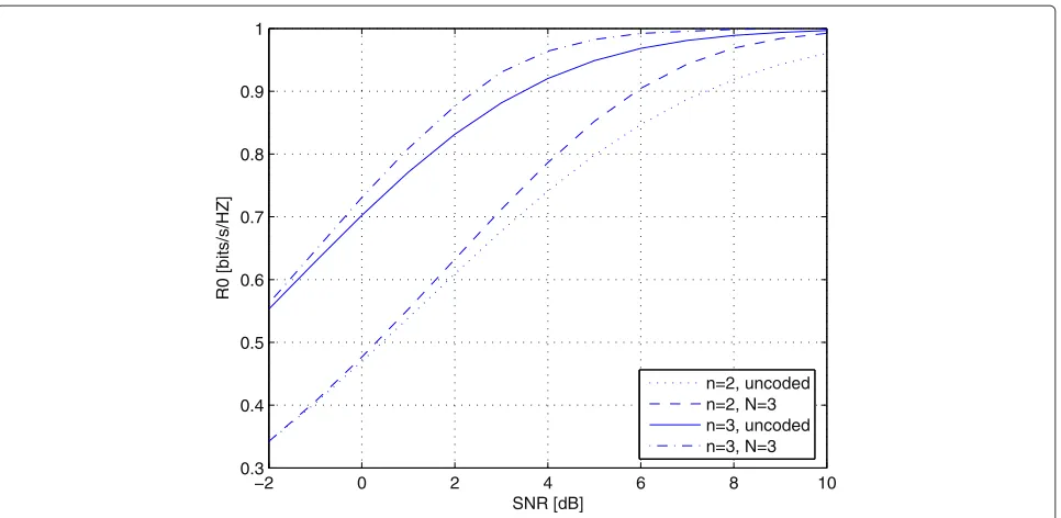
The diversity transform can be optimized with respect to the cutoff rate using either one of the aforementioned methods. It follows from Equation 20 that the optimum diversity matrix, denotedAM,N(m,n), is SNR dependent, withnandmbeing the number of transmit and receive antennas, respectively, and where M = 2, 4, 8, and 16 correspond to BPSK, QPSK, 8-PSK, and 16-QAM constel-lations, respectively. Good matrices have been obtained by employing numerical optimization based on either the gradient descent algorithm in the form of Equation 25, or by manipulating the three degrees of freedom of each constituent matrixTi,jof Equation 27. The main advan-tage of the former approach over the latter is its simplicity, particularly for large transform ordersN. The main dis-advantage of the former approach lies in its dependency on initial value for the matrixAand step size δ. When implemented correctly, both methods provide very similar results in terms of maximizing the cutoff rate. The cutoff rates thus obtained are plotted in Figure 2 as a function
of SNR, for someM,N,m, andnvalues. For all the cases shown, we assumed one receive antenna (i.e.,m=1), and the maximum achievable rate is 1 bit/sec/Hz, where for n=2, we used the orthogonal codeG2and BPSK modu-lation, and forn=3, we used the orthogonal codeG3with QPSK modulation since the rate ofG3is one half. Nice improvement in cutoff rate is observed with a transforma-tion order ofN = 3 compared to the uncoded scheme (corresponding to N = 1). An example of an optimal matrixAis given below, calculated using gradient descent algorithm as described in Subsection 4.2. It was derived for a scenario withn= 3 transmit antennas, transforma-tion order ofN = 3, rate 1 bit/sec/Hz and SNR of 4 dB. The parameters of the gradient descent algorithm were chosen as follows : initial step size, used in Equation 22, isδ = 0.03 ; the step size is decreased by a factor of 0.97 with each iteration. The initial value for the matrixAis a matrix of equal entries (normalized by a scalar to sat-isfy the condition (22)). After 100 iterations, the following matrix was derived: Equation 16 followed by substitution into Equation 20, a cutoff rate of 0.965 bit/sec/Hz is achieved, compared to an uncoded scheme (whereAis taken to be the identity matrix of size 3) whose cutoff rate is 0.92 bit/sec/Hz.
5 Detection of DST codes
We first describe an optimum detection algorithm for DST codes. Since optimum detection can be quite com-putationally complex, we also derive a linear detector for these codes. For linear detection, we shall introduce and justify the use of DRT matrices different from those obtained in the previous section.
5.1 Optimum detection
Optimum detection of DST codes, in the sense of mini-mizing the bit error probability, can be carried out in two steps:
1. Decode the orthogonal ST code by employing Proposition 1.
2. Reconstruct the source bits using maximuma posteriori (MAP) criterion according to the specific diversity matrixAapplied.
−2 0 2 4 6 8 10 0.3
0.4 0.5 0.6 0.7 0.8 0.9 1
SNR [dB]
R0 [bits/s/HZ]
n=2, uncoded n=2, N=3 n=3, uncoded n=3, N=3
Figure 2Optimal cuttoff rates, R0, for different transform orders and antenna array sizes.
simpler, suboptimum detection method is proposed in the form of linear detection.
5.2 Linear detection - the MMSE receiver The detection rule is of the form
Y=BR+h,
whereRis given by Equation 9. The matrixBand the vec-torhare chosen to minimize the mean square error (MSE) of the receiver:
MSE=E{†} =E{(Y−Y)·(Y−Y)†}.
Assuming, as before, thatH(defined in Equation 10) is known to the receiver, the components ofYare indepen-dent and iindepen-dentically distributed (i.i.d) with zero mean and energyEs, the MMSE (minimum MSE) receiver is given by
Y=Es·(HA)†[Es·(HA)·(HA)†+σ2·H]−1·R. Owing to the orthonormality ofA, the MMSE receiver can be formulated simply as:
Y=A†R, (28)
whereis a diagonal matrix whose non-zero elements are as follows:
λii=
Es· ˜hi Es·(h˜i)2+σ2· ˜hi
.
Substituting Equation 9 into Equation 28, we get
Y=A†(HAY+)=A†HAY+A†=A†PAY+A†,
whereP = His a diagonal matrix with elements given by
pii =
Es·(h˜i)2 Es·(h˜i)2+σ2· ˜hi
;
thejth element ofYis given by
yj=yj N
i=1
|aij|2pii+ N
k=1,k=j N
i=1
piia∗ijaikyk+ N
i=1
giia∗ijγi.
(29)
From Equation 29, it follows that the MMSE receiver is biased. This bias can degrade BER performance for large signal constellations. In order to eliminate this biasing, each elementyjis divided byNi=1|aij|2pii.
It can be shown [5] that in order to minimize the vari-ance of the MSE (when represented as a function of the channel fadings) the non-zero elements of the matrixA should satisfy
|aij| = 1 √
N;
we shall employ the normalized Hadamard matrix, which satisfies this property.
5.3 Suboptimum detection
In view of the previous subsection, suboptimum detection can be summarized as follows:
5 10 15 20 25 30 10−6
10−5 10−4 10−3 10−2 10−1
1 bit/sec/Hz, 2 transmit, 1 receive antennas
BER
SNR (dB)
no DRT
DRT 2, optimal estimation DRT 3, optimal estimation DRT 8, linear estimation DRT 32, linear estimation
Figure 3Bit error rate versus SNR for codes at 1 bit/s/Hz; two transmit, one receive antenna.
2. Use the linear MMSE receiver described in this section to get an estimate ofY. Recover the corresponding source bits.
The performance of the proposed DST codes and detec-tion algorithms are quantified in the next secdetec-tion by computer simulations.
6 Simulation results
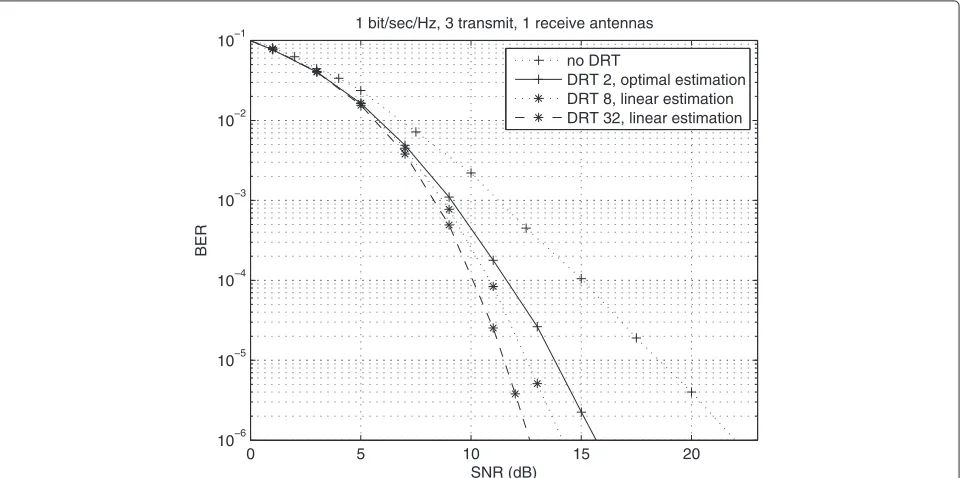
This section provides bit error rate performance obtained via simulations for various casesb. Figures 3, 4, and 5 present bit error rate performance for transmission of 1 bit/s/Hz using two to four transmit antennas, one receive antenna, DRT orderNof 1 to 3 when employing MAP decoding (note thatN = 1 amounts to employing
0 5 10 15 20
10−6 10−5 10−4 10−3 10−2 10−1
1 bit/sec/Hz, 3 transmit, 1 receive antennas
BER
SNR (dB)
no DRT
DRT 2, optimal estimation DRT 8, linear estimation DRT 32, linear estimation
0 5 10 15 20 10−6
10−5 10−4 10−3 10−2 10−1
1 bit/sec/Hz, 4 transmit, 1 receive antennas
BER
SNR (dB)
no DRT
DRT 2, optimal estimation DRT 8, linear estimation DRT 32, linear estimation
Figure 5Bit error rate versus SNR for codes at 1 bit/s/Hz; four transmit, one receive antenna.
standard ST coding with no DRT). For high DRT orders of N =8 andN =32, also shown in the figures, we employ a suboptimal, yet reduced complexity, linear detection.
For the two-transmit antenna case, BPSK has been used with the codeG2. For three and four transmit antennas, we used QPSK with codesG3, andG4, respectively. It can be seen, for bit error rate 10−6, that order-2 DRT provides about 10, 6, and 5 dB coding gain for two, three, and four
transmit antennas, respectively, as compared to regular (non-diversified) ST code. The corresponding gains for orders 8 and 32 are 11, 8, and 6 dB and 15, 9.5, and 7 dB, respectively.
Note that the gain decreases as the number of transmit antennas increases. This can be attributed to the fact that a large number of antennas already exploit much of the attainable diversity gain. For the same reason, when the
0 2 4 6 8 10 12 14 16
10−6 10−5 10−4 10−3 10−2 10−1
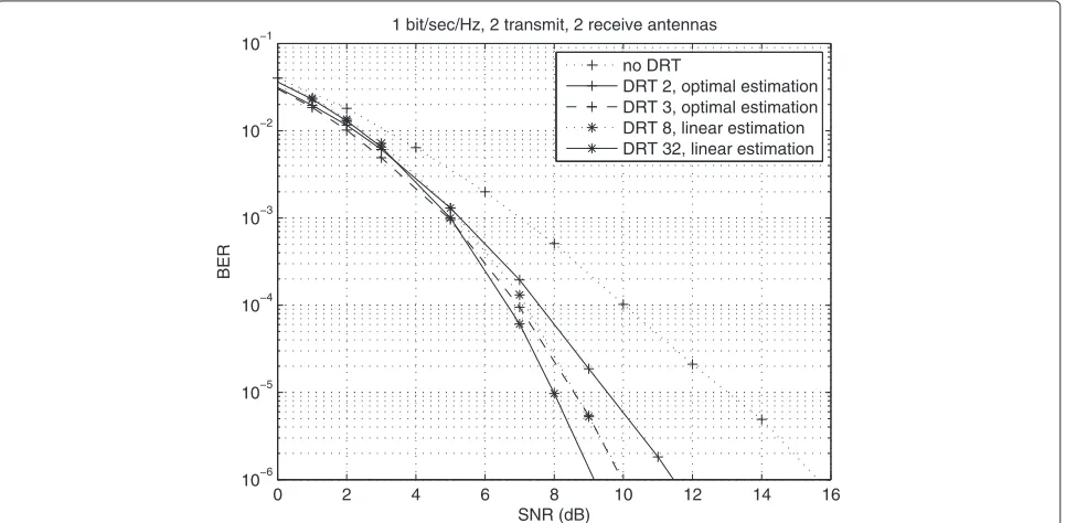
1 bit/sec/Hz, 2 transmit, 2 receive antennas
BER
SNR (dB)
no DRT
DRT 2, optimal estimation DRT 3, optimal estimation DRT 8, linear estimation DRT 32, linear estimation
5 10 15 20 10−6
10−5 10−4 10−3 10−2 10−1
2 bits/sec/Hz, 2 transmit, 1 receive antennas
BER
SNR (dB)
no DRT
DRT 32, linear estimation
Figure 7Bit error rate versus SNR for codes at 2 bits/s/Hz; two transmit, one receive antenna.
number of receive antennas is increased to two (Figure 6), the obtained gains are 4, 2, and 1.5 dB for two, three, and four transmit antennas (N = 2), respectively; 5.5, 3.5, and 2.5 dB (N = 8 with linear detection); and 6.5, 4, and 2.7 dB (N = 32 with linear detection), respectively. Clearly, in all scenarios where linear detection is involved, larger gains are obtained (with reduced complexity) due
to employing increased DRT order; this is achieved for the price of somewhat increased latency at the receiver.
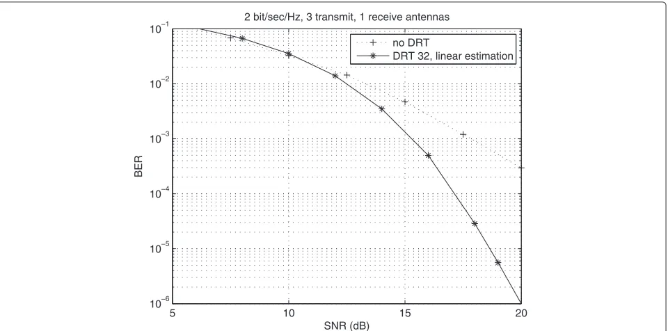
Figures 7 and 8 show bit error probability results for transmission of 2 bits/s/Hz with two to three transmit antennas, one receive antenna, and diversity order 1 and 32. The transmission using two antennas employs QPSK constellation with the codeG2. For three transmit
5 10 15 20
10−6 10−5 10−4 10−3 10−2 10−1
2 bit/sec/Hz, 3 transmit, 1 receive antennas
BER
SNR (dB)
no DRT
DRT 32, linear estimation
antennas, 16-QAM constellation is used with the code G3.
Extensive simulations were carried out also for higher spectral efficiencies. Consider transmission of 3 bits/s/Hz using two to four transmit antennas and one receive antenna. For two transmit antennas, 8-PSK and the code G2 have been used. For three and four transmit anten-nas, we used 16-QAM along with the codes H3 andH4, respectively. For bit error rate of 10−6, diversity transform of order 2 provides about 9, 5.2, and 3 dB gain for two, three, and four transmit antennas, respectively. Diversity transforms of order 8 and 32 provide gains of 6, 5, and 4.2 dB and 12.5, 8, and 5.2 dB, respectively, when using linear detection.
Finally, it is demonstrated, for the block-fading chan-nel, that when a communication scheme is limited by the number of antennas, the diversity transform can effec-tively compensate for the loss in spatial diversity. An upper bound on the error probability of codes using an orthogonal design is given by [14]
Perror=. SNR−mn(1−r), (30)
where r is the spatial multiplexing gain and =. denotes exponential equality.
Assume given a coding scheme employingn transmit antennas,mreceive antennas and diversity transform of orderN as proposed herein. It is interesting to compare this scheme with a scheme havingntransmit andN ·m receive antennas.
In view of the error exponent (30), the latter scheme can be used to lower bound the performance of the proposed scheme. The latter scheme can achieve spatial diversity gain of N ·mn, while that of the first scheme depends on the temporal diversity gain provided by the diversity transform. Comparing Figures 3, 4, and 5 (for N = 2) with Figure 6 and the results for three to four transmit, two receive antennas (with no DRT) reveal that the lat-ter curves are about 2 to 3 dB betlat-ter than the former set of curves. This is due to the fact that a short trans-form cannot achieve the full diversity provided by a large antenna array. However, when a communication scheme is limited by the number of antennas, the diversity trans-form can effectively compensate for this loss in spatial diversity.
7 Conclusions
Space-time block codes of increased diversity are structed for MIMO Rayleigh fading channels. This con-struction combines orthogonal designs with diversity transforms, thus providing ST block coding scheme of high diversity gain that can be easily tailored for any
antenna array and signal constellation. Two detection algorithms are described: optimum detection and sub-optimum detection employing linear estimation at the receiver. Specific construction of codes with bandwidth efficiencies of 1, 2, and 3 (bits/s/Hz) are detailed. Among the properties of DST codes, we can mention its high diversity, low implementation complexity, high trans-mission rates, and the fact that the distribution of the obtained code alphabet is close to Gaussian. Finally, we note that quasi-orthogonal codes [15,16] can be used in the framework of DST codes in order to achieve even higher data rates.
Endnotes
aIn the sequel, we shall omit the subscriptias the
analysis is the same for any valuei.
bHereinafter, whenever the detector is linear, we
employed the Hadamard transform of appropriate dimensions as the DRT matrix. Otherwise, we employed the optimal matrices obtained in Section 4.
Appendix
ST codes used in this work
Rate 12ST orthogonal codes are given by:
G3=
and rate34ST orthogonal codes given by:
H3=
The authors declare that they have no competing interests.
Acknowledgements
Received: 29 May 2013 Accepted: 30 December 2013 Published: 15 January 2014
References
1. SM Alamouti, A simple transmit diversity technique for wireless communications. IEEE J. Sel. Areas in Commun.16, 1451–1458 (1998) 2. V Tarokh, H Jafarkhani, AR Calderbank, Space-time block codes from
orthogonal designs. IEEE Trans. on Inform. Theory45, 1456–1467 (1999) 3. X Giraud, E Boutillon, JC Belfiore, Algebraic tools to build modulation
schemes for fading channels. IEEE Trans. on Inform. Theory.43, 938–952 (1997)
4. E Bayer-Fluckiger, F Oggier, E Viterbo, New algebraic constructions of rotatedZn-lattice constellations for the Rayleigh fading channel. IEEE Trans. on Inform. Theory50, 702–714 (2004)
5. D Rainish, Diversity transform for fading channels. IEEE Trans. on Comm.
44, 1653–1661 (1996)
6. AJ Salomon, O Amrani, Space-time block codes using diversity transform, inProc. IEEE Information Theory Workshop on Wireless Networks(Solstrand, 1–6 Jul 2007), pp. 1–5
7. HF Lu, Explicit constructions of multi-block space-time codes that achieve the diversity-multiplexing tradeoff, inProc. IEEE International Symposium on Information Theory(Seattle, 9–14 July 2006), pp. 1149–1153 8. X Lin, RS Blum, Improved space-time codes using serial concatenation.
IEEE Commun. Letters.4, 221–223 (2000)
9. J Boutros, E Viterbo, Signal space diversity: a power- and
bandwidth-efficient diversity technique for the Rayleigh fading channel. IEEE Trans. on Inform. Theory44, 1453–1467 (1998)
10. AJ Salomon, O Amrani, Product construction of codes for Rayleigh-fading channels. IEEE Trans. on Inform. Theory53, 416–428 (2007)
11. A Salomon,Iterated Code Constructions,(Tel Aviv University, Tel Aviv Israel, 2011)
12. N Abramson,Information Theory and Coding,(McGraw-Hill, New York, 1963)
13. DK Faddeev, VN Faddeeva,Computational Methods of Linear Algebra,
(WH Freeman and Company, New York, 1963)
14. L Zheng, DNC Tse, Diversity and multiplexing: a fundamental tradeoff in multiple-antenna channels. IEEE Trans. on Inform. Theory49, 1073–1096 (2003)
15. H Jafarkhani, A quasi-orthogonal space-time block code. IEEE Trans. Comm.49, 1–4 (2001)
16. C Yuen, YL Guan, TT Tjhung, Quasi-orthogonal space-time block codes with minimum decoding complexity. IEEE Trans. Wireless Comm.
4, 2089–2094 (2005)
doi:10.1186/1687-1499-2014-8
Cite this article as:Salomon and Amrani:Increased diversity space-time coding
using the diversity transform.EURASIP Journal on Wireless Communications and
Networking20142014:8.
Submit your manuscript to a
journal and benefi t from:
7Convenient online submission
7Rigorous peer review
7Immediate publication on acceptance
7Open access: articles freely available online
7High visibility within the fi eld
7Retaining the copyright to your article