R E S E A R C H
Open Access
Jointly optimized multiple Reed-Muller codes for
wireless half-duplex coded-cooperative network
with joint decoding
Saqib Ejaz
1*, Fengfan Yang
1, Hongjun Xu
2and Shunwai Zhang
3Abstract
In this paper, we present a novel technique to use Reed-Muller (RM) codes for the wireless half-duplex coded-cooperative network. Plotkin’s construction allows RM codes to be used in a coded-cooperative scheme. To improve the cooperation provided by the relay in a coded-cooperative scheme, a design criterion and an efficient algorithm to achieve the design objective are also suggested. Moreover, union bounds for average error probability are determined, for both the cooperative and the non-cooperative schemes based on RM codes in the Rayleigh fading channel. To generalize the proposed RM coded-cooperative scheme, we examined different RM codes at the source and at the relay. At the destination, soft decision maximum likelihood decoding (SD-MLD) and majority logic decoding are used. Theoretical analysis and Monte-Carlo simulations show that the proposed RM coded-cooperative scheme clearly outperforms the RM non-cooperative scheme.
Keywords:Average error probability; Coded-cooperative diversity; Joint multi-RM code design; Joint decoding; Majority logic decoding; Maximum likelihood decoding; Plotkin’s construction; Partial encoding; Reed-Muller codes
1 Introduction
In modern wireless communications, one of the most important aspects is to reduce the channel impairments over the signal propagation. The signal is distorted in a number of ways as it propagates through a wireless channel. Many phenomena like reflection, diffraction, and scattering are responsible for the loss of quality of service (QoS) [1]. Various diversity techniques such as time, frequency, polarization, and space are suggested in the literature to improve the quality of a wireless chan-nel [1]. However, spatial diversity has proven to be the most effective diversity technique to combat the channel effects [2-4]. Unfortunately, many mobile communica-tion devices are not capable to exploit this spatial diver-sity due to the constraints such as power, size, and hardware complexity. However, novel ideas such as the three-terminal communication [5] and the user cooper-ation to provide uplink diversity via single antenna sharing
[6-8] provide suitable alternative and allow the mobile de-vices to take advantages of the spatial diversity.
The idea of coded-cooperative diversity was first intro-duced in [9]. In order to achieve the coded-cooperative diversity, many distributed coding schemes have been reported in the literature such as the convolutional codes [10,11], distributed space-time coding [12,13], dis-tributed low-density parity-check codes (D-LDPC) [14,15] and distributed turbo codes (DTC) [16,17] and more recently the polar codes [18,19]. However, the BER performance of binary turbo and the LDPC codes largely depends on the information block size, the longer the better and vice versa, whereas for the short non-binary turbo and LDPC codes, reasonable performances under the iterative decoding are reported in [20,21]. In many existing and emerging applications (such as device-to-device and sensor networks), it is possible to have sce-narios, which may transmit small information block size. Thus, it provides one of the many motivations for our work to develop such a coded-cooperative scheme, which may be useful particularly for applications having small in-formation block size and require low encoding and decod-ing complexity. For any communication system, there is * Correspondence:[email protected]
1College of Electronic and Information Engineering, Nanjing University of
Aeronautics and Astronautics, Nanjing 210016, Jiangsu Province, People’s Republic of China
Full list of author information is available at the end of the article
and always will be a trade-off between the complexity and performance as suggested in [22].
In this paper, we present a novel coded-cooperative scheme based on Reed-Muller (RM) codes [23,24]. The recursive algebraic structure of RM codes makes them different and in many ways superior over other linear block codes. RM codes have low encoding and decoding complexity which is a desirable feature in most of the practical applications [25]. Their algebraic structure and construction allows them to be used as suitable channel codes in a coded-cooperative communication system. There are various methods already suggested in the lit-erature about the recursive construction of RM codes [26]. However, in order to use RM codes in a coded-cooperative diversity scheme, we use Plotkin’s construction [27]. In a coded-cooperative scheme, the source and the relay terminal jointly contribute to build good codes at the destination. The code is good at the destination as it is superior in its decoding properties as compared to the code transmitted at the source without any coded cooperation. To get the maximum coding gains from this joint construction, a joint decoding scheme is estab-lished at the destination. The relay plays a vital role in the code construction at the destination and a good code design at the relay can greatly improve the overall performance of the coded-cooperative scheme. Based on this fact, we also propose an efficient algorithm to design a good code at the relay. In [28,29], Plotkin’s con-struction is used in conjunction with the superposition coding for cooperative broadcasting in wireless networks. In superposition coding [30], two modulated subcode se-quences, produced by the two coordinated and independ-ent sources, are combined at the antenna of the receiver (also referred as over the air mixing [31]). The received modulated signals from the two cooperative broadcast-ing sources are added over the field of real numbers (or depending on the signal constellation used). That scheme also showed promising BER performance gains; however, the scheme proposed in this paper is entirely different from the former in many ways. Firstly, we use Plotkin’s construction to construct a new code at the destination, and binary addition of unmodulated code-words takes place at the relay instead of real number addition as suggested in [28,29]. Secondly, there is only one source in our scheme, and there is no over the air mixing, whereas in [28,29], two independent source nodes broadcast their information to the destination node and over the air mixing is performed.
This paper is organized as follows: Section 2 presents a generalized three-terminal-based coded-cooperative network and gives the channel description. In Section 3, preliminaries related to the RM codes and Plotkin’s con-struction are presented. Section 4 presents the encoding scheme for RM coded-cooperative and non-cooperative
networks. In Section 5, the code design for the single-relay coded cooperation is presented. Performance ana-lysis for RM-code-based cooperative and non-cooperative schemes over the Rayleigh fading channel is presented in Section 6. Section 7 presents various Monte-Carlo simula-tions and shows the significance of the proposed RM coded-cooperative scheme. Section 8 presents the conclu-sion of the article.
2 Three-terminal-based coded-cooperative communication model
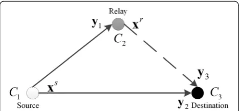
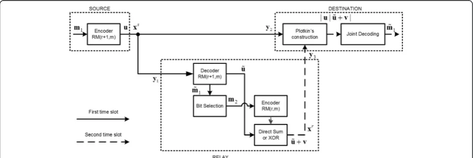
A generalized three-terminal-based coded-cooperative scheme [5] is shown in Figure 1.
It comprises three communication terminals or nodes such as the sourceS, the relayR, and the destinationD. All these terminals have single antenna to transmit and receive, and they communicate with each other in half-duplex mode. The complete end-to-end transmission of an information sequence takes two time slots. During the first time slot, the sourceSencodes the message bits using the codeC1and modulates binary codeword using the binary phase shift keying (BPSK) modulation. The BPSK-modulated signalxs¼ xs
1;xs2;…;xsL
is a vector of length Land is broadcasted to the relay and the destin-ation, where each entry inxsisxs
l∈ −f 1;þ1g; l¼1;2;…;
L. The received signal vectory1at the relay is given as:
y1¼hs;rxsþns;r ð1Þ
where ns,r= [ns,r(1),ns,r(2),…,ns,r(L)] is a vector of com-plex additive Gaussian noise with each component ns,r(j), (j= 1, 2,…,L) is a zero-mean complex Gaussian random variable (RV) with independent real and im-aginary components of varianceN0/2, andhs,r= [hs,r(1), hs,r(2),…,hs,r(L)] is a channel fading coefficient vector whose entries hs,r(j), (j= 1, 2,…,L) are independent and identically distributed (i.i.d.) complex Gaussian random variables with zero-mean and 0.5 variance per dimension. In the case of the fast Rayleigh fading, the fading coeffi-cients change independently over the transmission of every symbol xs
l, whereas in the case of the slow Rayleigh
fading, the fading coefficients remain constant for the whole framexs and change independently over transmis-sion of every next frame. The signal received at the destin-ationy2during the first time slot is given as:
y2¼hs;dxsþns;d ð2Þ
wherehs,dis a channel fading coefficient vector and ns,d is a Gaussian noise vector which are defined similarly as
hs,randns,r, respectively.
During the second time slot, the recovered informa-tion bits at the relay node (received in the first time slot), are re-encoded using the codeC2. After BPSK modu-lation of the binary codeword, the relay transmits its signal xr¼ xr
1;xr2;…;xrL
to the destination node, where xr is a vector of lengthLand each entry inxrisxrl ∈ −f 1;þ1g; l¼1;2;…;L. The transmission ofxrto the destination during the second time slot is represented with a dashed line as shown in Figure 1.
The signal received y3 at the destination during the second time slot is modeled as:
y3¼hr;dxrþnr;d ð3Þ
wherehr,dis a channel fading coefficient vector and nr,d is a Gaussian noise vector which are defined similarly as
hs,r and ns,r. Finally, the overall received signal y at the destination is modeled as follows:
y¼j jy2y3j ð4Þ
where‘|’represents the concatenation of the two signals received during the first and the second time slots. This signalyis passed to the decoder to recover the informa-tion sequence generated at the source.
3 Fundamentals of RM codes
RM codes belong to a family of linear block codes, which have very nice mathematical properties. Before we discuss the motivation of this paper, let us present some preliminaries related to the RM codes and Plotkin’s con-struction. Mathematically, RM codes are best described using Boolean function as follows:
‘The rth order binary RM code ℛ(r, m) of block length n= 2m, for 0≤r≤m, is the set of all vectors f, where f(α1,α2,…,αm) is a Boolean function which is a polynomial of degree at mostr’[26], wheremandrare any positive integer. The binaryrthorder ℛ(r, m) code has the dimensionkgiven as:
k¼1þ m codes can be constructed in different ways such as algebra-ically,m-fold Kronecker product or by Plotkin’s construc-tion [25-27,32]. However, Plotkin’s construction provides
the motivation for utilizing RM codes in the coded-cooperative diversity scheme. RM codes of length 2m+ 1can be obtained via RM codes of length 2m using Plot-kin’s construction. Let C1(n,k1,d1) =ℛ(r+ 1, m) and C2(n,k2,d2) =ℛ(r, m) be the two RM codes, where n is the codeword length,k1and k2, are the dimensions, and d1 and d2 are the minimum Hamming distances of the codes C1 and C2 respectively. Then, according to Plotkin’s construction, we get a new RM code such as, C~3 N~;k~;d3
where u,v are the binary codeword vectors, + is an addition over GF(2) field. The new code C3~ has the codeword lengthÑ= 2n, dimension~k¼k1þk2 and the minimum Hamming distance is given as [25]:
d3¼ min 2f d1;d2g ð7Þ
Plotkin’s construction is also referred to as |u|u+v| construction.
4 RM coded-cooperative and non-cooperative schemes
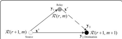
Based on the coded-cooperative scheme in Section 2, we propose a generalized three-terminal-based RM coded-cooperative scheme as shown in Figure 2.
However, this time, the codes used at the source and at the relay are two distinct RM codes C1(n,k1,d1) =
ℛ(r+ 1, m) and C2(n,k2,d2) =ℛ(r, m), respectively. The information sequence m1generated at the source takes two time slots to be recovered at the destination. During the first time slot,k1message bits are encoded using theℛ(r+ 1, m) code, and the resultant codeword vectoruof lengthn= 2mis then BPSK-modulated. The modulated signal xs is broadcasted simultaneously to the relay and the destination nodes. The relay decodes the received signal y1 to recover the information se-quence transmitted at the source. The recovered infor-mation sequencem~1¼½m~1;m~2;…;m~k1may or may not
be error free, depending on theS-Rlink.
During the second time slot, the relay performspartial encodingusingℛ(r, m) code and selects onlyk2message bits out of k1recovered message bits, wherek2<k1. The
term partial indicates that not all the recoveredk1 mes-sage bits are re-encoded at the relay, thus encoding complexity is significantly reduced at the relay terminal. The selection criteria ofk2message bits is explained in Section 5 and has significant impact on the overall per-formance of the RM coded-cooperative scheme. The se-lectedk2information bits are then encoded usingℛ(r, m) code to produce the codewordvof the lengthn= 2m. In the next step, the direct sum of two codewordsũandvis determined, i.e., |ũ+v| whereũis a recovered codeword at the relay,ũ may or may not equal toudepending on the S-Rlink condition. However, for notational simplicity, we assume ũ=u in the rest of the paper unless specified. This direct sum is BPSK-modulated asxrand transmit-ted to the destination node during the second time slot as shown with a dashed line in Figure 3.
At the destination node, the signals transmitted at the source and at the relay during the first and second time slots, respectively, are concatenated as in (4). The demodulated codeword |u|u+v| at the destination be-longs to a new code C3which is jointly constructed by the source and the relay nodes. Moreover, C3⊆C~3¼ℛ
rþ1; mþ1
ð Þdue to the fact that the message bitsm2 encoded at the relay are the function of the message bits
~
m1 recovered at the relay, i.e., m2ðm~1Þ. In other words, message bits at the relay m2 are not independent or generated randomly, they are in fact subset ofm~1. Ifm2 is the function ofm~1, then the codeC2generated at the relay is also a function of the code generated at the sourceC1i.e.,C2(C1). Then, the jointly constructed code
C3at destination is given as:
C3¼j jC1C1þC2ð ÞjC1 ð8Þ
whereC3has the codeword lengthN= 2nand the mini-mum Hamming distance isd3≥min{2d1,d2}, for RM codes particularly d3= min{2d1,d2} as given in (7). Since m2
~ m1
ð Þ, therefore we have all possible codewords at the des-tination equal to 2k1 instead of 2k1þk2 as 2k2 codewords
are expurgated. The codeword obtained at the destination due to joint construction of the source and the relay is given as:
jujuþvj ¼ ju1|fflfflfflfflfflfflfflffl{zfflfflfflfflfflfflfflffl};u2;…;un 1stpart
jðzfflfflfflfflfflfflfflfflfflfflfflfflfflfflfflfflfflfflfflfflfflfflfflfflffl}|fflfflfflfflfflfflfflfflfflfflfflfflfflfflfflfflfflfflfflfflfflfflfflfflffl{uþvÞ1;ðuþvÞ2…;ðuþvÞn 2ndpart
j
ð9Þ
The first part in (9) is in fact a codeword generated at the source, and the second part is a codeword generated at the relay. The second part provides additional redun-dancy, which is exploited by the joint decoding at the destination. The word ‘joint’here refers to the fact that the signals received from the source y2and the relayy3 during different time slots are jointly decoded as a single received vector y= |y2|y3|. The code rate of the overall distributed code isR0
c¼k1=2n.
Due to the rich algebraic structure of the RM codes, there are several decoding methods already reported in the literature. Majority decoding was the first algorithm proposed for RM codes. Recursive algorithms and multi-stage decoding algorithms are discussed in [33,34]. A simplified algorithm for soft-decision decoding of RM codes is suggested in [35]. RM codes of longer lengths can be decomposed to the constituent codes and sub-optimal techniques can be used for the decoding, with less complexity [25]. However, in this paper, we use the majority logic decoding and soft decision maximum like-lihood decoding (SD-MLD) with an assumption of per-fect channel state information (CSI) known at the destination. For joint SD-MLD, the decision metric used is given as:
ζðy;xÞ ¼ jy2j jy3−jhs;dxshr;dxrj F ð10Þ
where ‖.‖F represents the Frobenius norm. The joint decoding (majority logic or SD-MLD) of the overall concatenated received signaly= |y2|y3| results in the infor-mation sequencem~ of length~k¼k1þk2as follows:
~
m¼ jm~1jm~2j
~
m¼ j|fflfflfflfflfflfflfflfflfflfflffl{zfflfflfflfflfflfflfflfflfflfflffl}m~1;m~2;…;m~k1
1stpart
jm~k1þ1;…;m~k2
zfflfflfflfflfflfflfflfflfflffl}|fflfflfflfflfflfflfflfflfflffl{2ndpart
j ð11Þ
where we are interested only in the first part m~1, which is in fact the original message transmitted at the source.
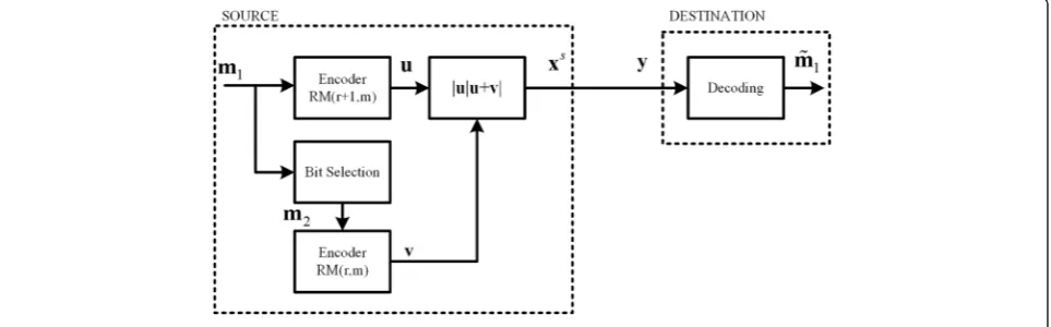
In order to show the effect of cooperative diversity, and a suitable benchmark to the proposed RM coded -cooperative scheme, we consider a non-cooperative RM-code-based transmission scheme as shown in Figure 4.
In a non-cooperative scheme, both the source and the relay units assumed in the coded-cooperative scheme are considered to be a single source unit, i.e., the source employs two encodersC1=ℛ(r+ 1, m) andC2=ℛ(r, m); information bit selection for encoding by theC2=ℛ(r, m) encoder is similar to the coded-cooperative scheme, ex-plained in the next section. The direct sum of the two codewords u+v generated by each encoder is then concatenated with the codewordu generated by the first encoderC1=ℛ(r+ 1, m) by an additional block construct-ing the |u|u+v| codeword, which is then modulated and sent to the destination.
5 Code design for partial encoding at the relay
In this section, we suggest a design criterion to select k2 message bits out ofk1recovered message bits at the relay. An efficient algorithm to achieve the design criterion is also proposed. The codeword |u|u+v|∈C3of minimum Hamming distanced3= min{2d1, d2} may occur at the destination due to the following worst case scenario
that is when a codeword of minimum Hamming distance d1 is generated at the source, i.e., wt(u) = 2m−r−1=d1 (where wt is the Hamming weight), and at the relay, the all-zero codeword, i.e., v=0⇒wt(v) = 0 is generated (where0bold style is the all-zero codeword vector). Con-sequently, the weight of the codeword |u|u+v| con-structed at the destination is:
d3¼wtðjujuþvjÞ ¼wtðjujujÞ ¼2d1 ð12Þ
Therefore, to avoid this worst case also referred to as the first worst case scenario hereafter, we propose a de-sign criterion as follows:
‘Select a subset C3 of C~3¼ℛðrþ1; mþ1Þ code at the destination with as few as possible codewords of minimum Hamming distanced3= 2m−r.’
In order to meet the design criterion, the code at the relay must be designed in such a way that it avoids the worst case scenario. Let us first define some nomencla-ture before we present design steps of the proposed al-gorithm to achieve the design objective.
i. The first worst case scenario is defined as an event when the codeword generated at the source achieves minimum Hamming weight, i.e., wt(u) =d1and at the relay, the all-zero codeword, i.e.,v=0⇒wt(v) = 0 is obtained. LetK1represent the number of
occurrences for the first worst case scenario. ii. The second worst case scenario is defined as an
event in which the codeword of minimum Hamming distanced1st3 ¼d3is obtained at the
destination, due to the joint encoding of the source and the relay nodes. LetK2represent the number of occurrences for the second worst case scenario, whereK2=Kbis also referred to as the error coefficient of any linear block code.
iii. Similarly, the third worst case scenario is defined as an event in which the codeword of Hamming distanced2nd3 just greater than thed1st3 is obtained at
the destination, due to the joint encoding of the source and the relay nodes, whered1st3 <d2nd3 <…<dN3th, anddN3this the maximum Hamming distance of a codeword. LetK3represent the number of occurrences for the third worst case scenario.
iv. |Ω| represents the cardinality of any setΩ. v. a→brepresents that the selection of quantity a
results in the quantityb.
The design steps of the proposed algorithm are as follows:
1) DetermineA= {mκ}, which is a set of all message
blocks that result in the codewords of minimum Hamming distanced1at the source, whereκ= 1, 2, intermediately fixed at the relay.
4) Selectλg→min(K1) and store it in the set C. If |C| = 1, then go to step 9 else proceed to step 5.
5) Determine the second worst case scenarios K2, ∀mκ∈A and ∀λg∈C by keeping each unique combination λg intermediately fixed at the relay. 6) Selectλg→min(K2) and store it in the set D. If |D| = 1,
then go to step 9 else proceed to step 7.
7) Determine the third worst case scenariosK3,∀mκ∈ A and∀λg∈D by keeping each unique combination
λgintermediately fixed at the relay.
8) Selectλg→min(K3) and store it in the set E. If |E| = 1, then go to step 9 else arbitrarily choose any unique combinationλg∈E and proceed to step 9.
9) The optimum combinationλo=λgis selected. End of the algorithm.
Finally, the optimum combination λo is fixed at the relay, and only thek2information bits defined byλoare further encoded using ℛ(r, m) code to get the code-wordv.
The algorithm is efficient in a way that it does not re-quire all the message blocks 2k1 generated at the source to
be considered for the algorithm search. Only theϑ<<2k1
number of message blocks, which results in codewords of minimum Hamming distance d1 at the source is consid-ered in the design of an algorithm. The total number of elementary operations (additions and multiplications) Θif the algorithm converges at step 6 is as follows:
Θ¼Sϑ½2n kð 1þk2Þ þN−2 ð14Þ
whereΘshows that the complexity to determine the op-timal combination λo increases with an increase in the dimension of the codes, i.e.,k1andk2used at the source and at the relay, respectively, and with the codeword block lengthn. It should be noted that if algorithm con-verges at step four, then the complexity of the algorithm is obviously less than Θand increases if algorithm does not converge at step 6. The straightforward proof of (14) is given in theAppendixsection.
For a better understanding of the proposed algorithm, we present the following illustrative example.
5.1 Example 1
Consider a RM coded-cooperative scheme in which the source employs C1(n1= 16,k1= 11,d1= 4) =ℛ(2, 4) code and the relay employs C2(n2= 16,k2= 5,d2= 8) =ℛ(1, 4) code, and their joint coded cooperation results in a new code C3⊆C˜3¼ℛð2; 5Þ at the destination. The source can encodek1= 11 message bits, and the relay can encode onlyk2= 5 message bits out ofk1= 11 message bits (recov-ered at the relay). The selection procedure ofk2= 5 out of
k1= 11 message bits according to the proposed algorithm is explained as follows.
In the first step, we determine A= {mκ} i.e., the set of all message blocks which result in the codewords of minimum Hamming distance d1= 4 at the source. For
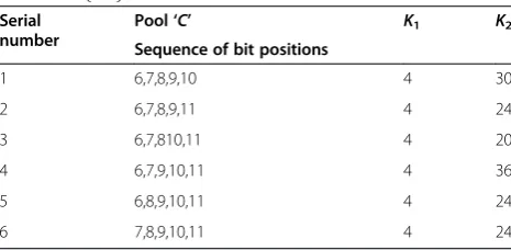
ℛ(2, 4) code,ϑ= |A| = 140, this parameter can be deter-mined using computer simulations or by using the gen-eralized formula in [26]. Then, according to step 2, we have S= 462 unique combinations λg= [λ1,λ2,…,λ5] using (13) in which 5 bit positions can be chosen out of total 11 bit positions. Let these unique combinations be stored in B= {λg}.. In the third step, K1 is determined ∀λg∈B and the minimum number of the first worst cases is observed to be min(K1) = 4. In the fourth step, the unique combinations which resulted in min(K1) = 4 cases, i.e., λg→min(K1) are stored in C as shown in Table 1.
The cardinality of the set C is |C| = 6. Since, |C| > 1 we proceed to step 5. In the fifth step,K2is determined ∀λg∈C by keeping each λg intermediately fixed at the relay and transmitting allmκ∈A. The unique combination
λg→min(K2) = 20 also shown in Table 1 is stored in the set
D, where |D| = 1, therefore, we proceed to step 9, and the optimum combinationλois chosen asλo=λg= {6, 7, 8, 10, 11}→min(K2) = 20 and the algorithm search is terminated.
6 Average error probability 6.1 AWGN channel
per information bitPb(E) for any binary linear code with code rateRcand dimension kusing SD-MLD is given as [36]:
whereγbis the signal-to-noise ratio (SNR) per informa-tion bit Q(.) is a Gaussian Q function, and wi is a Hamming weight of a codeword. For probability of bit errorPb, we substitutePb(E) in the following equation:
Pb¼
XN
w¼dmin
Aw
k Pbð ÞE ð15bÞ
whereNis a codeword length,Awis a weight enumerat-ing factor and usually determined via exhaustive com-puter search. However, for RM codes, Aw can also be determined analytically as suggested in [26].
As an example, we present the performance analysis of the designed codeC3⊆~C3¼ℛð2; 5Þ, which is joint con-structed by ℛ(2, 4) and ℛ(1, 4) codes. To compute Pb, we first determine the weight distribution of the codeC3 via exhaustive computer search and is given as follows:
A0¼1;A8¼20;A12¼416;A16¼1;174;
A20¼416;A24¼20;A32¼1
Thus, a probability of bit error Pb for the code C3 using (15-b) is given as:
Pb¼
The bound in (16) is plotted in Figure 5 along with the numericalsimulation resultsfor the codeC3⊆~C3¼ℛð2; 5Þ, both results are in close agreement to each other particularly
at high SNR. The BER performances of some of the well-known RM codes such asℛ(2, 4),ℛ(2, 5) andℛ(3, 7) [25] are also shown in Figure 5. The idea is to show the perform-ance of the proposed code with reference to the existing well-known RM codes in the literature. However, the code rate is not uniform except for the ℛ(2, 5) and ℛ(3, 7) codes, i.e.,Rc= 1/2, and it will not be fair to compare the BER performances of other codes with different rates. However, the code ℛ(3, 7) with the highestdminand in-formation lengthkoutperforms all the other codes; more-over, this result is intuitive as seen from (15-a) and (15-b).
6.2 Rayleigh fading channel
In this section, we present average error probability bounds for the RM-based non-cooperative and coded-cooperative schemes over the fast Rayleigh fading chan-nel. At first, we consider a non-cooperative scheme, and using the techniques outlined in the available literature [10,36], the unconditional error probability is as follows:
Pbð Þ ¼E
The integral in (17) can be determined using available computer packages. Then, to determine the average error probability Pb, we substitute Pb(E) in (15-b). For a proposed RM coded-cooperative scheme, the uncondi-tional error probability is as follows:
Pbð Þ ¼E
The upper bound can easily be obtained by assuming sin2ϕ= 1 and is given as:
From (18), it can be seen that the diversity order of the coded-cooperative scheme is equal to the Hamming weight w=w1+w2, which is similar to the diversity order of the non-cooperative scheme. Moreover, in the case of the fast Rayleigh fading ifγRD=γSD, then the BER performances of the coded-cooperative and non-cooperative schemes are identical. In the fast Rayleigh fading, the relay node can provide extra benefit only if
γRD>γSD. However, in the case of the slow Rayleigh fad-ing, the true significance of the relay node (or coded co-operation), i.e., the spatial diversity, is observed even if
γRD=γSD, and the scenarios such as γRD>γSD can be
beneficial but not mandatory. These facts are also sup-ported with the help of Monte-Carlo simulations pre-sented in the next section.
7 Simulation results and observations
For the simulations, we consider two different cases to generalize our proposed RM coded-cooperative scheme and the code design algorithm at the relay. In the first case, ℛ(2, 4) and ℛ(1, 4) codes are considered for en-coding, and in the second case, we use ℛ(2, 5) and
ℛ(1, 5) codes for the encoding. The Rayleigh fading channel is considered among all the communication nodes with perfect CSI known at all corresponding re-ceivers. All transmitting nodes transmit at an equal power, and BPSK modulation is used for the transmis-sion of a codeword over radio frequency (RF) channel. BER simulations are reported in terms of SNR per infor-mation bit, defined asγSD/Rc, where γSD is the SNR per code bit between theS-Dlink andRc is the code rate at which the source encodes message bits.
7.1 Case I
The first case employs C1=ℛ(2, 4), and C2=ℛ(1, 4) codes for encoding. In the case of coded cooperation, C1=ℛ(2, 4) code is used at the source andC2=ℛ(1, 4) code is used at the relay, and they jointly construct a new codeC3at the destination, whereC3⊆C~3¼ℛð2; 5Þ. The source encodesk1= 11 message bits, and the relay encodes
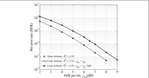
onlyk2= 5 bits, which are selected fromk1bits (decoded at the relay). The optimum bit selection rule was deter-mined in Example 1, i.e.,λo= {6, 7, 8, 10, 11}. The code rate at the source isRc= 11/16, and the code rate of the overall distributed code is R0c ¼11=32 . For case I, the source node of non-cooperative scheme consists of two encoders C1=ℛ(2, 4) andC2=ℛ(1, 4). The information bit selec-tion for encoding by the second encoder C2=ℛ(1, 4) is similar to the coded-cooperative scheme. The direct sum of the two codewordsu+vgenerated by each encoder is determined and then concatenated with the codeword u∈ℛ(2, 4) resulting in the codeword |u|u+v|∈C3, which is then BPSK-modulated and sent to the destination. Both coded-cooperative and non-cooperative schemes are com-pared under the condition of an equal rate (11/32) for a fair comparison. BER performance simulations for case I are presented for six different scenarios.
scheme outperforms the non-cooperative scheme only when γRD=γSD+ 3 dB. The theoretical and simulated performance of the designed code C3 validate each other.
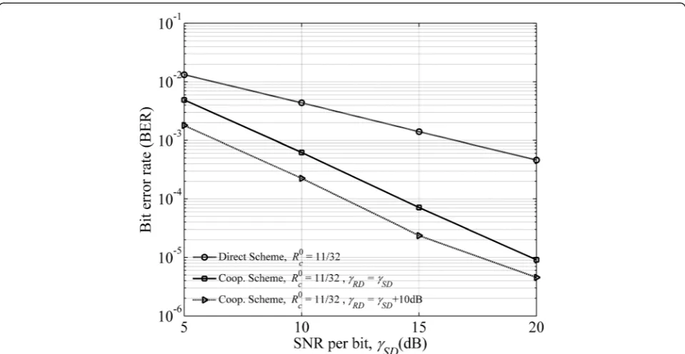
The first scenario (with the fast Rayleigh fading channel) shows only one side of the picture and does not give insight to the concept of path diversity due to the relay node. Therefore, to show the effect of path diversity due to the relay node, we now present a second scenario, which assumes a slow Rayleigh fading channel among all the communication nodes. The BER performances of RM coded-cooperative and non-cooperative schemes are shown in Figure 7 over the slow Rayleigh fading channel and SD-MLD decoding at the destination. It is observed that the RM coded-cooperative scheme with γSR=∞, γSD=γRDoutperforms the non-cooperative scheme with a coding gain margin of more than 10 dB at BER≈10−5, which improves further when γRD=γSD+ 10 dB. This is where the true capability of the coded-cooperative sys-tem comes into display, and merely constructing a good code at the destination is not enough to combat the channel fading. It is due to these joint construction and the joint decoding features of the coded-cooperative scheme, which make it superior over the non-cooperative alternatives.
The third scenario is the continuity of the second sce-nario with the difference that the majority logic decod-ing is used at the destination. The BER performances of RM coded-cooperative and non-cooperative schemes over a slow Rayleigh fading channel are shown in Figure 8,
where the RM coded-cooperative scheme with γSR=∞, γSD=γRD provides a coding gain of more than 5 dB at BER≈10−3, which improves further when γRD=γSD+ 10 dB.
In the fourth scenario, we present the effectiveness of the proposed algorithm for code design at the relay. Therefore, we present the comparison between the two RM coded-cooperative schemes: in one scheme, the code at the relay is designed according to the proposed design criterion, whereas in the other scheme, the code at the relay is randomly selected; in other words, it is not necessary that it avoids the worst case scenarios. Moreover, in both of the schemes, we assumeγRD=γSD and joint SD-MLD is used at the destination and the channel is fast Rayleigh fading. It is shown in Figure 9, that the optimally designed relay provides 1.2-dB gain at BER≈10−5as compared to the randomly designed relay. The loss in the BER performance of randomly designed relay is obvious since the coded-cooperative scheme does not achieve full diversity.
coverage, and outage probability [38]. From Figure 10, it can be seen that atγSR= 8 dB, the relay is in outage, and hence, the overall BER performance of the cooperative sys-tem is significantly degraded.
This degradation is due to the uncontrolled error propagation at the relay. The most common remedy to
control this error propagation is the utilization of cyclic redundancy check (CRC) at the relay as suggested in [10]. Based on the CRC, the relay decides whether to participate in the cooperation or not; however, error control at the relay is beyond the scope of this paper, and interested reader is referred to [39]. It is observed Figure 7SD-MLD, RM coded-cooperative and direct schemes over a slow Rayleigh fading channel withℛ(2, 4) andℛ(1, 4) codes.
that at γSR= 15 dB the performance of the coded-cooperative scheme significantly improves and approaches the performance of the coded-cooperative scheme with idealS-Rlink, i.e.,γSR=∞.
Finally, for the sixth scenario, we examine the per-formance of proposed coded-cooperative scheme and
non-cooperative scheme based on the power con-sumed to achieve the same BER. The best scheme is the one that consumes less power to achieve the same BER; this type of analysis for cooperative and non-cooperative systems is also presented in [40]. Figure 11 shows a power consumption comparison between the Figure 9SD-MLD, optimally designed relay vs. randomly designed relay over a fast Rayleigh fading channel.
coded-cooperative scheme and the non-cooperative scheme.
The source transmission power Ps is used as a proxy to the SNR per bit γSD and changed independently. In Figure 11, BER curves are plotted for different levels of relay transmission powerPr= 14, 16.8, and 19 dBm. It is observed that to achieve BER≈10−3the non-cooperative scheme consumes Ptotal=Ps= 56.2 mW, where Ptotal is the total transmission power and the coded-cooperative scheme consumed only Ptotal=Ps+Pr= 28.2 mW, where Ps= 3.1 mW,Pr= 25.1 mW. Moreover, under a total power constraint, i.e., Ptotal= 56.2 mW, the coded-cooperative scheme achieves BER≈1.4 × 10⁻⁴. The results clearly show that the coded-cooperative scheme outperforms the non-cooperative scheme based on power consumption. Further, it is observed that the overall BER performance of the coded-cooperative scheme improves whenPris increased at the relay even if thePsis kept fixed.
7.2 Case II
In this case, the two codes used for encoding areC1=ℛ(2, 5) and C2=ℛ(1, 5). For RM coded-cooperative scheme
C1=ℛ(2, 5) code is used at the source and C2=ℛ(1, 5) code is used at the relay, and at the destination, they jointly construct a new code C3, where C3⊆~C3¼ℛ
2; 6
ð Þ. The source terminal encodesk1= 16 message bits, and the relay encodes k2= 6 message bits, which are in fact chosen according to the proposed design criterion. It is observed during the search for an optimum combination
λo
that there are two combinationsλ1andλ2inD, which result in equal number ofK2worst cases whereDis:
D¼ λλ1¼ð7;8;9;11;13;14Þ 2¼ð6;8;9;11;13;14Þ
ð20Þ
Since |D| > 1, therefore we proceed to step 7 of the de-sign algorithm. In the seventh step, we observed that again the two combinations λ1 and λ2 result in equal and minimum number ofK3worst cases. Consequently, |E| = 2 > 1 therefore, we select arbitrarily λ1 as the optimum combination, i.e.,λo=λ1. The code rate at the source is Rc= 1/2, and the overall code rate of the coded-cooperative scheme isR0
c ¼1=4.
coded-cooperative scheme outperforms the non-cooperative scheme with a margin of more than 10 dB at BER≈10−5.
8 Conclusions
We presented a novel RM coded-cooperative diversity scheme for half-duplex wireless relay networks. The RM coded-cooperative scheme clearly outperforms the RM non-cooperative scheme, and comprehensive BER per-formance gains are observed for the SD-MLD (≥10 dB) and for the majority logic decoding (≥5 dB) relative to the non-cooperative schemes in Rayleigh fading channels.
The BER performance gains achieved are due to the following factors. At first, it is the joint construction of two channel codes such asℛ(r+ 1,m) code (of small mini-mum Hamming distanced1) used at the source andℛ(r,m) code used at the relay to construct aℛ(r+ 1,m+ 1) code (of large minimum Hamming distance d3) at the destin-ation. The second factor is the design criterion and an effi-cient algorithm to ensure that the jointly constructed code C3has the better weight distribution among all the pos-sible subcodes of the codeC~3. Thirdly, the joint decod-ing of the two signals received in two different time slots, transmitted at the source and the relay, provides additional coding gain. Finally, it is the path diversity provided by the relay node that contributes to improve the overall BER performance of the RM coded-cooperative scheme. The performance gains achieved due to the RM coded-cooperative scheme are shown with the help of
numerical simulations and validated with the theoretical bounds.
In this paper, we presented only two RM codes at the source. However, the proposed methodology of coded cooperation can be extended in general to other longer length and higher order RM codes as well as to any other family of binary linear block codes. The proposed encoding scheme and code design algorithm at the relay can easily be extended to the relay/user and multi-hop systems; we leave this as our future research work. Moreover, further work is required in performing the sub-optimum decoding of the jointly constructed code particularly of longer lengths.
9 Appendix
To encode one message of block lengthk1at the source, the number of multiplication operations performed is
Θ
s ¼k1n, wherenis the number of columns in the gen-erator matrix employed at the source and at the relay, and the number of addition operations isΘþs ¼ðk1−1Þn, hence, the total elementary operations involved in encoding one message block are Θ1s ¼Θs þΘþs ¼nð2k1−1Þ. Then, for ϑ message blocks which result in the codewords of minimum Hamming distanced1at the source, the number of elementary operations becomes:
Θsource¼ϑnð2k1−1Þ ð21Þ
Similarly, at the relay, the total number of elementary operations to encodeϑmessage blocks each of lengthk2is:
Θrelay ¼ϑnð2k2−1Þ þ |{z}ϑn Direct−Sum
ð22Þ
where the second part in (22) is due to the direct sum of the two codewords generated at the source and at the relay. Hence, the total number of elementary operations performed for each unique combination λg intermedi-ately fixed at the relay and∀mκ∈A is:
Θ1¼ϑnð2k1−1Þ þϑnð2k2−1Þ þϑn
¼ϑn½2ðk1þk2Þ−1
ð23Þ
Thus, for S unique combinations intermediately fixed at the relay andϑ message blocks, the number of elem-entary operations is:
ΘS¼Sϑn½2ðk1þk2Þ−1 ð24Þ
To determine the Hamming weight of a binary code-word |u|u+v| of length N, N−1 additions are per-formed. Thus, for ϑ message blocks and S unique combinations, the number of addition operations at the destination becomesSϑ(N−1). Finally, the total number of elementary operations is given as:
Θ¼Sϑ½2n kð 1þk2Þ þN−2 ð25Þ
Note: Θ is the number of total elementary operations performed if algorithm converges at step 6 of the design algorithm.
Competing interests
The authors declare that they have no competing interests.
Acknowledgements
The authors are thankful to the editor and the anonymous reviewers for their technical comments and suggestions to improve the overall quality of this manuscript
Author details
1
College of Electronic and Information Engineering, Nanjing University of Aeronautics and Astronautics, Nanjing 210016, Jiangsu Province, People’s Republic of China.2School of Engineering, University of KwaZulu Natal, King George Avenue V, Durban 4041, South Africa.3College of
Telecommunication and Information Engineering, Nanjing University of Posts and Telecommunications, Nanjing 210003, People’s Republic of China.
Received: 6 May 2014 Accepted: 17 March 2015
References
1. TS Rappaport,Wireless Communications: Principles and Practice, vol. 2
(Prentice Hall PTR, New Jersey, 1996)
2. S Alamouti, A simple transmit diversity technique for wireless communications. IEEE J Sel. Area. Comm.16(8), 1451–1458 (1998) 3. V Tarokh, N Seshadri, AR Calderbank, Space-time codes for high data rate
wireless communication: performance criterion and code construction. IEEE Trans. Inform. Theor.44(2), 744–765 (1998)
4. V Tarokh, H Jafarkhani, AR Calderbank, Space-time block codes from orthogonal designs. IEEE Trans. Inform. Theor.45(5), 1456–1467 (1999) 5. EC Van Der Meulen,Three-Terminal Communication Channels. Advances in
Applied Probability, 1971, pp. 120–154
6. JN Laneman, GW Wornell, DN Tse. An efficient protocol for realizing cooperative diversity in wireless networks. InProceedings of 2001 IEEE
International Symposium on Information Theory(IEEE, Washington, DC, 2001), p. 294
7. A Sendonaris, E Erkip, B Aazhang, User cooperation diversity. Part I. System description. IEEE Trans. Comm.51(11), 1927–1938 (2003)
8. A Sendonaris, E Erkip, B Aazhang, User cooperation diversity. Part II. Implementation aspects and performance analysis. IEEE Trans. Comm. 51(11), 1939–1948 (2003)
9. TE Hunter, A Nosratinia, Cooperation diversity through coding. in
Proceedings of the 2002 IEEE International Symposium on Information Theory
(IEEE, Lausanne, Switzerland, 2002), p. 220
10. TE Hunter, A Nosratinia, Diversity through coded cooperation. IEEE Trans. Wireless Comm.5(2), 283–289 (2006)
11. A Stefanov, E Erkip, Cooperative coding for wireless networks. IEEE Trans. Comm.52(9), 1470–1476 (2004)
12. S Yiu, R Schober, L Lampe, Distributed space-time block coding. IEEE Trans. Comm.54(7), 1195–1206 (2006)
13. Y Li, X-G Xia. Full diversity distributed space-time trellis codes for asynchronous cooperative communications. inProceedings of the IEEE International Symposium on Information Theory, ISIT 2005(IEEE, Adelaide, SA, 2005), pp. 911–915
14. A Chakrabarti, A De Baynast, A Sabharwal, B Aazhang, Low density parity check codes for the relay channel. IEEE J. Sel Area. Comm.
25(2), 280–291 (2007)
15. J Hu, TM Duman, Low density parity check codes over wireless relay channels. IEEE Trans. Wireless Comm.6(9), 3384–3394 (2007) 16. B Zhao, MC Valenti, Distributed turbo coded diversity for relay channel.
Electron. Lett.39(10), 786–787 (2003)
17. MC Valenti, B Zhao. Distributed turbo codes: towards the capacity of the relay channel. in58th IEEE Vehicular Technology Conference, 2003. VTC 2003-Fall,vol. 1, (IEEE, Orlando, FL, USA, 2003), pp. 322–326
18. R Blasco-Serrano, R Thobaben, M Andersson, V Rathi, M Skoglund, Polar codes for cooperative relaying. IEEE Trans. Comm.60(11), 3263–3273 (2012) 19. Q Zhan, M Du, Y Wang, F Zhou, Half-Duplex relay systems based on polar
codes. IET Comm.8(4), 433-440 (2014)
20. G Liva, E Paolini, B Matuz, S Scalise, M Chiani, Short turbo codes over high order fields. IEEE Trans. Comm.61(6), 2201–2211 (2013)
21. C Poulliat, M Fossorier, D Declercq, Design of regular (2, d/sub c/)-LDPC codes over GF (q) using their binary images. IEEE Trans. Comm. 56(10), 1626–1635 (2008)
22. DJ Costello, GD Forney Jr, Channel coding: the road to channel capacity. Proc. IEEE95(6), 1150–1177 (2007)
23. DE Muller, Application of Boolean algebra to switching circuit design and to error detection. Electron. Comput. Trans. IRE Professional Group3, 6–12 (1954)
24. I Reed, A class of multiple-error-correcting codes and the decoding scheme. Inform. Theor. Trans. IRE Professional Group4(4), 38–49 (1954)
25. L Shu, S Lin, DJ Costello,Error Control Coding: Pearson Education India, 2004 26. FJ MacWilliams, NJA Sloane,The Theory of Error-Correcting Codes, vol. 16
(Elsevier, 1977).
27. M Plotkin, Binary codes with specified minimum distance. Inform. Theor. IRE Trans.6(4), 445–450 (1960)
28. R Morelos-Zaragoza. On iterative decoding of two-level superposition codes for cooperative broadcasting based on QPSK and 4-PAM constellations. In
Military Communications Conference, 2010-MILCOM 2010(IEEE, San Jose, CA, 2010), pp. 2369–2374
29. R Morelos-Zaragoza,A Plotkin-Alamouti Superposition Coding Scheme for Cooperative Broadcasting in Wireless Networks, 2009. arXiv preprint arXiv:0901.2270
30. T Cover, Broadcast channels. IEEE Trans. Inform. Theor.18(1), 2–14 (1972) 31. P Bergmans, TM Cover, Cooperative broadcasting. IEEE Trans. Inform. Theor.
20(3), 317–324 (1974)
32. NJ Sloane, D Whitehead, New family of single-error correcting codes. IEEE Trans. Inform. Theor16(6), 717–719 (1970)
33. I Dumer, Recursive decoding and its performance for low-rate Reed-Muller codes. IEEE Trans. Inform. Theor.50(5), 811–823 (2004)
34. I Dumer, K Shabunov, Recursive error correction for general Reed–Muller codes. Discrete Appl. Math.154(2), 253–269 (2006)
35. I Dumer, Soft-decision decoding of Reed-Muller codes: a simplified algorithm. IEEE Trans. Inform. Theor.52(3), 954–963 (2006)
37. M Janani, A Hedayat, TE Hunter, A Nosratinia, Coded cooperation in wireless communications: space-time transmission and iterative decoding. IEEE Trans. Signal Process.52(2), 362–371 (2004)
38. JN Laneman, DN Tse, GW Wornell, Cooperative diversity in wireless networks: efficient protocols and outage behavior. IEEE Trans Inform. Theor 50(12), 3062–3080 (2004)
39. T Van Nguyen, A Nosratinia, D Divsalar, Bilayer protograph codes for half-duplex relay channels. IEEE Trans. Wireless Comm.
12(5), 1969–1977 (2013)
40. M Patrick, S Ashutosh, A Behnaam, On building a cooperative
communication system: testbed implementation and first results. EURASIP Journal on Wireless Communications and Networking. Hindawi Publishing Corporation (2009). doi:10.1155/2009/972739
Submit your manuscript to a
journal and benefi t from:
7Convenient online submission 7Rigorous peer review
7Immediate publication on acceptance 7Open access: articles freely available online 7High visibility within the fi eld
7Retaining the copyright to your article
![Figure 5 SD-MLD, BER performances of ℛ(2, 4), C3⊂C~ 3 ¼ ℛð 2; 5Þ, ℛ(2, 5), and ℛ(3, 7) [25] over an AWGN channel.](https://thumb-us.123doks.com/thumbv2/123dok_us/950264.1116090/8.595.57.540.88.340/figure-mld-ber-performances-d-awgn-channel.webp)