Optimal Power Distribution Control for Multicode
MC-CDMA with Zero-Forcing Successive
Interference Cancellation
Mizhou Tan
Agere Systems, 1110 American Parkway NE, Allentown, PA 18109, USA Email:[email protected]
Christian Ibars
Centre Tecnol`ogic de Telecomunicacions de Catalunya, C/Gran Capit`a 2-4, 08034 Barcelona, Spain Email:[email protected]
Yeheskel Bar-Ness
Center for Communications and Signal Processing Research (CCSPR), Department of Electrical and Computer Engineering (ECE), New Jersey Institute of Technology (NJIT), University Heights, Newark, NJ 07102, USA
Email:[email protected]
Received 10 August 2003; Revised 11 March 2004
Multicarrier CDMA (MC-CDMA) has become a promising candidate for future wireless multimedia communications for its ro-bustness to frequency-selective fading and its flexibility in handling multiple data rates. Among different multirate access schemes, multicode MC-CDMA is attractive for its high performance, good flexibility in rate matching, and low complexity. However, its performance is limited by self-interference (SI) and multiuser interference (MUI). In this paper, a zero-forcing successive inter-ference cancellation (ZF-SIC) receiver is used to mitigate this problem for multicode MC-CDMA. Furthermore, optimal power distribution control (PDC), which minimizes each user’s bit error rate (BER), is considered. Our results show that, in correlated Rayleigh fading channels, the ZF-SIC receiver integrated with the optimal PDC dramatically improves the performance of the mul-ticode MC-CDMA system in comparison with other receivers proposed in the literature. Moreover, the optimal PDC significantly outperforms the PDC based on equal BER criterion, particularly under a short-term transmit power constraint.
Keywords and phrases:multicode, multicarrier CDMA, zero-forcing, successive interference cancellation, power distribution control.
1. INTRODUCTION
Multicarrier CDMA (MC-CDMA) combines multicarrier modulation (MCM) and DS-CDMA, and is characterized by its robustness to channel frequency selectivity and its simple receiver structure [1,2,3,4]. Multirate MC-CDMA schemes were proposed to support multimedia applica-tions in future wireless communicaapplica-tions [5]. Multicode MC-CDMA is one of the multirate access schemes in which different symbols of each user are transmitted in par-allel by employing different spreading codes. Compared with other multirate access schemes, multicode MC-CDMA presents better performance, higher rate matching capa-bility, and lower complexity [6]. However, the capacity of MC-CDMA is mainly limited by self-interference (SI)1and
1SI denotes the interference among different symbols of the same user.
transmitter,2it is possible to integrate SIC with power dis-tribution control (PDC), which can improve system capacity significantly.
Since the integration of SIC and PDC was proposed for increasing system capacity, extensive research has been done in this area. Nevertheless, most of the work focused on a single-rate, single-carrier CDMA system with a matched fil-ter (MF) SIC (MF-SIC) receiver. The equal bit error rate (BER) criterion, which is suitable for a system where all users aim to achieve comparable BER performances, was adopted in many references to derive the power distribution [7,9,10]. In [7], it is shown that, when ignoring decision errors, a geo-metric distribution of the receive power provides equal BER. In [9], equal BER performance is analyzed for linear SIC3 in AWGN channels. In [10], with nonlinear SIC, the power distribution for equal BER is obtained using gradient search considering all error patterns. As it has been concluded in the literature, the equal BER PDC benefits SIC significantly by increasing the reliability of earlier detected users. However, in CDMA systems, with the increase of system load, the per-formance of the MF degrades quickly, which limits the eff ec-tiveness of the SIC. Hence, it is more meaningful to integrate PDC with SIC for more powerful detection techniques, such as ZF and minimum mean square error (MMSE).
In this paper, we investigate a PDC algorithm suitable for the nonlinear ZF-SIC receiver in a multicode MC-CDMA system. For such a system, PDC becomes more important than for a single-rate system, since without PDC it is cus-tomary to let the transmit power of each user be evenly dis-tributed among all its spreading codes, which reduces the efficiency of SIC. Furthermore, as it is shown, the PDC for a multicode system requires a different approach from pre-viously studied single-rate systems. In the multicode case the equal BER criterion only leads to a suboptimal solution for PDC; it forces equal BER for the symbols transmitted in parallel on different spreading codes of a given user, but it does not minimize its BER, which is the average over all parallel-transmitted symbols. Therefore, we propose an opti-mal PDC solution, that minimizes each user’s BER while en-suring the same BER for different users. Both short-term and long-term transmit power constraints are considered. With a short-term power constraint, the transmit power is kept the same for every channel realization, while with a long-term constraint, the transmit power is adapted with channel vari-ations [11]. Simulation results in correlated Rayleigh fading channels show a remarkable performance improvement for the multicode MC-CDMA system in comparison to other re-ceivers proposed in the literature. Furthermore, the ZF-SIC with the optimal PDC significantly outperforms that with the equal BER PDC, particularly under the short-term power constraint.
Note that the proposed PDC scheme is of practical in-terest since it can also be easily adopted by a CDMA system
2We also assume that the channel is kept unchanged during the feedback. 3With linear SIC, soft decisions are employed for interference cancella-tion, while with nonlinear SIC, hard decisions are employed.
with closed loop power control (CLPC), which adjusts trans-mit power among different users with a limited amount of feedback from the receiver, as a form of a vector of power-up and power-down bits.4
The remainder of this paper is organized as follows. The nonlinear ZF-SIC receiver for uplink multicode MC-CDMA is described in the next section. The equal BER PDC is dis-cussed in Section 3and is followed by the optimal PDC in Section 4, with the performances of both PDC strategies an-alyzed under short-term and long-term transmit power con-straints. Simulation results are presented and discussed in Section 5. Finally, a conclusion is drawn.
2. NONLINEAR ZF-SIC RECEIVER FOR QUASISYNCHRONOUS UPLINK MC-CDMA
Consider a quasisynchronous uplink MC-CDMA in which all users are coordinated to transmit synchronously, with small, tolerated transmit time offsets. Signals received from different users have time offsets due to different propaga-tion delays and channel delay spread. Symbol guard inter-vals larger than the maximum receive time offset are used to avoid intersymbol interference (ISI). The receiver is assumed synchronized to the user with the smallest delay. Thus, after discarding the guard intervals at the receiver, the quasisyn-chronous system can be analyzed as a synquasisyn-chronous system. To focus our attention on the ZF-SIC receiver, we assume no frequency offset and no nonlinear distortion.
With K active users in the system, the kth (k =
1, 2,. . .,K) user is assignedlk linearly independent spread-ing codes. With a total of N subcarriers, the number of utilized spreading codes is L = K
k=1lk ≤ N. The block diagram of the transmitter for the kth user is shown in Figure 1. As depicted in this figure, the data is first 1 : lk serial-to-parallel (S/P) converted, then, each one of the par-allel symbols is replicated into N copies and multiplied by a preassigned spreading code of length N (frequency do-main spreading). After combining each chip oflk symbols, a discrete-time multicarrier modulation is performed by an N-point IDFT. Then, after parallel-to-serial (P/S) conversion to form an OFDM symbol (time domain), a cyclic prefix of proper length ∆is inserted between successive symbols to avoid intersymbol interference (ISI). Finally, following radio frequency (RF) upconversion, the signalsk(t) is transmitted through the fading channel.
The complex equivalent lowpass transmit signalsk(t) can be expressed as
sk(t)= +∞
i=−∞ lk
l=1 N
n=−Ng+1
ak,lbk,l(i)
×
N
m=1
ck,l,m·ej2π(mn/N)p
t−iTs−nTs N+Ng
.
(1)
Userk
S/P
1–lk
ck,1k,N . . .
ck,1k,1 . . .
ck,1,N . . .
ck,1,1
Copying and spreading
. .
. IDFT P/S
Guard interval insertion
sk(t) RF upconversion
sk(t)
Figure1: Block diagram of the transmitter of thekth user in uplink multicode MC-CDMA.
In the above equation,idenotes theith OFDM symbol in-terval [(i−1)Ts,iTs), whereTs = Ts+∆andTsis the ef-fective OFDM symbol duration without insertion of a cyclic prefix. Subscriptndenotes thenth sample (in the time do-main) during each Ts and m denotes the mth subcarrier. Ng =N·∆/Tsdenotes the number of samples during each ∆. Also,ak,l,bk,l(i) ∈ [1,−1] andck,l,mdenote the transmit signal amplitude, theith BPSK-modulated symbol, and the mth chip of thelth spreading codeck,lfor thekth user, re-spectively. Finally, p(t) is the rectangular pulse shape func-tion.
A Rayleigh fading channel, corresponding to the worst case of no line-of-sight (LOS) component, is considered. By using a cyclic prefix of proper length, frequency-flat fading is obtained over each subcarrier [15]. With the assumption of time-invariant channel during eachTs, for thekth user, the channel can be represented by an (N×1) vectorhk, given by
hk=gk·
hk,1,hk,2,. . .,hk,N T
, (2)
wheregkdenotes the path loss between thekth user and the base station, andhk,nrepresents the fading over thenth sub-carrier, which is a complex Gaussian random variable with unit variance. In the uplink, different users’ channels are as-sumed independent, identically distributed (i.i.d.). Further-more, due to the proximity and partial overlap of the signal spectrum, correlated fading on different subcarriers is con-sidered. The correlation between two subcarriers depends on the frequency spacing between them and the RMS channel delay spreadτd[16,17].
At the receiver, after RF downconversion and discarding the cyclic prefixes, the received signalr(t) can be expressed as
r(t)=
+∞
i=−∞ K
k=1 lk
l=1 N
n=1
ak,lbk,l(i)
×
N
m=1
gkhk,mck,l,m·ej2π(mn/N)p
t−iTs−nTs N
+n(t),
(3)
where the additive white complex Gaussian noise process n(t) has zero mean and variance σ2. After demodulation (DFT), the output during theith effective OFDM symbol in-terval [(i−1)Ts,iTs) can be expressed in a compact matrix form as
x(i)=CAb (i) +η(i). (4)
In (4), C is the (N ×L) spreading code matrix corrupted by the Rayleigh fading channels, expressed as C = [C1,
C2,. . .,CK], where the (N×lk) matrixCk(k=1, 2,. . .,K) is given by
Ck=
ck,1,ck,2,. . .,ck,lk
, (5)
which containslkdifferent code vectors of thekth user. Each item in (5) can be expressed as
ck,l=hkck,l
=gkhk,1ck,l,1,hk,2ck,l,2,. . .,hk,Nck,l,N T
. (6)
Additionally,Ais an (L×L) diagonal matrix containing the transmit amplitudes of all symbols, given by
A=diag aT
1,aT2,. . .,aTK T
, (7)
where diag(·) denotes the diagonal matrix operator andak= [ak,1,ak,2,. . .,ak,lk]
T(k=1, 2,. . .,K).b(i) is an (L×1) vector containing the parallel-transmitted symbols of all users with normalized power, given by
b(i)=bT1(i),bT2(i),. . .,bTK(i) T
, (8)
wherebk(i)=[bk,1(i),bk,2(i),. . .,bk,lk(i)]T (k =1, 2,. . .,K). The (N×1) white Gaussian noise vectorη(i) has zero mean and covariance matrix σ2I, whereIis an (N×N) identity matrix.
After the matched filter, we have
y(i)=CH·x(i)
r(t) RF downconverter
Guard interval removal
r(t)
S/P ... DFT ... X
Match filter bank
Y
F Z
I−B Hard decision
device Nonlinear ZF-SIC
b
Figure2: Block diagram of a nonlinear ZF-SIC receiver for multicode MC-CDMA.
forl=0 toL−1 [b(i)]L−l
=hard decision
z(i)L−l
−l
m=1[A]L−l+m,L−l+m
·[Γ]L−l,L−l+mb(i)
L−l+m
end
Algorithm1
where we assume perfect CSI at the receiver. In the above equation, the cross-correlation matrix R = CHC is posi-tive definite in most cases. Hence, it can be uniquely de-composed as R = ΓHD2Γ, where Γ is upper triangular and monic (having all ones along the diagonal), and D =
diag([dT1,dT2,. . .,dTK]T) is a real (L ×L) diagonal matrix, wheredk = [dk,1,dk,2,. . .,dk,lk]T (k = 1, 2,. . .,K). By mul-tiplying both sides of (9) byD−2Γ−H, we obtain
z(i)=D−2Γ−H·y(i)
=ΓAb(i) +η(i), (10)
whereη(i) is an (L×1) Gaussian vector with uncorrelated components, whose covariance matrix equalsσ2
nD−2[8]. From (10), since Γ is upper triangular and η(i) has uncorrelated components, the receive symbols b(i) =
[bT1(i),bT2(i),. . .,bTK(i)]Tcan be recovered by back-substi-tution combined with symbol-by-symbol detection with Algorithm 1, where [x]jand [X]i,jdenote the jth element of a vectorxand the (i,j)th element of a matrixX, respectively. The block diagram of the nonlinear ZF-SIC receiver is shown inFigure 2, whereFD−2Γ−Hdenotes the feedforward ma-trix, whileI−BI−Γdenotes the feedback matrix.
From (10) andAlgorithm 1, we see that the SNRγLof the first detected symbol [b(i)]Lis the same as that of the ZF detector, given by [8]
γL=
A2
L,L σ2R−1
L,L
=
A2
L,L σ2D−2
L,L
, (11)
whereas other symbols are detected by subtracting a linear combination of previous hard decisions from z(i). In fact,
the later detected symbols may contain interference from the earlier detected ones due to decision errors. Otherwise, if all cancellations are perfect, the performance of the last detected symbol achieves the single-user bound (SUB).
By ignoring decision errors, the sufficient statistic for the (L−l)th (l=0, 1,. . .,L−1) symbol [b(i)]L−lcan simply be expressed as
z(i)L−l=[A]L−l,L−lb(i)L−l+
η(i)L−l, (12)
and similar to (11), the SNR can be expressed as
γL−l=
A2
L−l,L−l σ2D−2
L−l,L−l
. (13)
3. EQUAL BER PDC
With the equal BER criterion, each parallel-transmitted sym-bol achieves the same BER after the SIC. Clearly, the follow-ing equation should be satisfied:
γL=γL−1= · · · =γ1 (14)
or
A2 L,L
D−2 L,L
=
A2
L−1,L−1
D−2 L−1,L−1
= · · · =
A2
1,1
D−2 1,1
. (15)
3.1. Short-term transmit power constraint
Under each channel realization, the short-term transmit power constraintP is defined as
P = 1
Ltr
A2, (16)
where tr(X) denotes the trace of a matrixX. For a given chan-nel realization, from (13) and (14),Amust satisfy
A2L−l,L−l=γ|h·σ2D−2L−l,L−l (l=0, 1,. . .,L−1), (17)
whereγ|hdenotes the achievable SNR, which depends on the channel realization. Applying (16), we have
P =1
Lγ|hσ 2·
L−1
l=0
D−2L−l,L−l
=1
Lγ|hσ
2trD−2.
Therefore,γ|hcan be expressed as
γ|h= LP
σ2trD−2, (19)
and the power distribution is given by
A2L−l,L−l= L
D−2
L−l,L−l
trD−2 P (l=0, 1,. . .,L−1). (20)
Note thatAandDalso depend on the channel realization. We omit that in the notation for simplicity. Since decision errors are ignored,γ|his higher than what can actually be achieved in the real system. Therefore, with the equal BER PDC, un-der the short-term power constraint, the average BER perfor-mance obtained withγ|hin (19) leads to a lower bound (LB) of the BER of the ZF-SIC receiver. For BPSK modulation, it can be expressed as
BERLB−ST=EH
Qγ|h
=EH
Q
LP
σ2trD−2
, (21)
whereQ(·) denotes the tail of the error function, andEH[·] denotes the ensemble average over all channel realizations.
3.2. Long-term transmit power constraint
The long-term power constraintP is determined by the av-erage of powers over all channel realizations, which is
P =1
LEH
trA2. (22)
Therefore, for a certain channel realization, we can define P|h as the required power for achieving a SNRγ(which is kept the same for all channel realizations), and from (18), we have
P|h= 1 Lγσ
2trD−2. (23)
Substituting it into the power constraint expressed by (22), we obtain
P =EHP|h
=1
Lγσ
2·EHtrD−2. (24)
The SNRγfor a long-term power constraintP can be ex-pressed as
γ= LP
σ2EHtrD−2, (25)
and the power distribution under each channel realization is given by
A2
L−l,L−l=
LD−2 L−l,L−l
EHtrD−2P (l=0, 1,. . .,L−1). (26)
Similarly, under the long-term power constraint, the LB for the equal BER PDC can be expressed as
BERLB−LT=Qγ
=Q
LP
σ2EHtrD−2
. (27)
4. OPTIMAL PDC
With the equal BER PDC, the earlier detected symbols will be allocated more power since they are exposed to higher interference than the later detected ones. Hence, compared with the power distribution that ensures equal receive power, such an approach cancels interference more effectively by im-proving the reliability of symbols detected earlier. However, in a multicode system, the BER performance of each user is the average over all its parallel symbols transmitted on diff er-ent spreading codes. That is, for thekth user, its BER perfor-mance is the average over all thelkparallel transmit symbols, which can be expressed as
pe,k
a2k= 1
lk lk
l=1 pe,k,l
a2k,l
. (28)
Therefore, from the viewpoint of minimizing BER, the equal BER PDC is only suboptimal. In this section, the optimal power distribution is derived based on the criterion of mini-mizing each user’s BER.
4.1. Short-term transmit power constraint
With the short-term transmit power constraint P, under each channel realization, our optimization problem can be stated as follows. For thekth user, find the optimal power dis-tribution a2k∗ which satisfiesa2k∗ = arg mina2
k(pe,k(a 2 k)) sub-ject to
a2k∗,l ≥0
l=1, 2,. . .,lK,
1 lk
lk
l=1 a2∗
k,l =Pk,
(29)
where Pk is the transmit power allocated to thekth user, which satisfies
1 L
K
k=1
lkPk=P. (30)
Without loss of generality and for ease of comparison with the equal BER PDC, we assume different users have the same BER requirement, that is, pe,k(a2k∗)= pe,l(a2l∗) (k,l=
By ignoring cancellation errors, (28) can be rewritten as
It is clear that the BER minimization is a convex optimization problem with differentiable objects and constraint functions, for which a unique and global optimal solution exists. For the kth user, the optimal power distribution is found to be
a2∗
where ϑ∗k is the Lagrange multiplier, which can be found from the power constraint, expressed as
1
The Karush-Kuhn-Tucker (KKT) optimality conditions [18] are used to solve this problem, as shown in Appendix A. Also, for ϑ∗k ∈ (0, 1/4σ2d−k,l2], a2k∗,l ∈ [0, +∞) and it is monotonically decreasing with ϑ∗k. Hence, for ϑ∗k ∈ (0, maxl=1,2,...,lk(1/4σ2d−
2
k,l)],Pk∈[0, +∞) and also, it is mono-tonically decreasing withϑ∗k. Based on these conclusions and with (31), it is not difficult to find thatpe,k(a2k) is monotoni-cally decreasing withPk.
For simplicity, considering only two users, under each channel realization, the algorithm can be summarized as fol-lows. (1) Let P1 = P and let P2 = 0. (2) Apply (34), algorithm can be extended to the scenario where the number of users is greater than two.5As in the previous section, since decision errors are ignored, then for thekth (k=1, 2,. . .,K) user, the LB of the proposed optimal PDC, under the short-term power constraint can be expressed as
BER(LBk)−ST= 1
5With a large number of users, the complexity of the search algorithm might become high. However, in practice, the power constraint on all users can be relaxed to a separated power constraint on each user, under which the optimal PDC can easily be derived.
4.2. Long-term transmit power constraint
With the long-term power constraint P, the optimization problem can be stated as follows. For the kth user, find the optimal power distribution a2k∗ which satisfies a2k∗ = arg mina2 over all channel realizations, given by
EHpe,k
Similarly,Pksatisfies (30).
After solving the KKT optimality conditions, shown in Appendix B, we obtain the optimal power distribution for thekth user, which is expressed exactly as (32) or (33), while ϑ∗k is obtained from the following power constraint:
1
instead of (34). A similar algorithm as stated in the previous subsection can be applied, but in this case,ϑ∗k is found over all channel realizations. Also, under the long-term power constraint, for thekth user, the LB of the optimal PDC over all channel realizations is given by
BER(LBk)−LT= 1
From the above analyses, it can be found that with the op-timal PDC, whend−2
k,l ≥1/4σ2ϑ∗k (ϑ∗k has to be determined), no power will be allocated to thelth symbol of thekth user, which implies that, unlike the equal BER PDC, which al-ways consumes more power to compensate for higher noise power6for achieving the same SNR, the optimal PDC allo-cates no power to those symbols whose noise power is equal to or higher than a certain level (1/4σ2ϑ∗
k), while allocat-ing more power for other “better” symbols, to ensure more reliable transmissions. Also, for those symbols whose noise power is less than a certain level (1/4σ2ϑ∗
k), then from (32), under a chosen ϑ∗k, since a2k∗,l is monotonically increasing withd−2
k,l, more power will be allocated to the symbols with higher noise power to ensure the reliability of earlier detected symbols. These two different PDC strategies, the equal BER PDC, and the optimal PDC result in different BER perfor-mances, which will be presented in the next section.
6From (13),d−2
Table1 Simulation parameters.
Parameters Values in simulations
Bandwidth 100 MHz
τd 25 ns
N 16
g g=g1=g2= · · · =gK=1
Modulation BPSK
Number of channels 1000
Symbols for each channel 160
5. SIMULATION RESULTS AND DISCUSSIONS
An indoor-correlated Rayleigh fading channel model is em-ployed in the simulations. The total available bandwidth is 100 MHz, with τd = 25 nanoseconds, and the number of subcarriers is 16. Without loss of generality, the path loss of different users is assumed equal, denoted bygandg =g1=
· · · = gK =1. We consider here only uncoded MC-CDMA
with Walsh Hadamard spreading codes. For simplicity, we as-sume two users, each employing 8 codes in the fully loaded system, and a slow fading channel, constant over a frame of 160 BPSK-modulated symbols. All simulation results are ob-tained over 1000 channel realizations. For easy reference, the simulation parameters are included inTable 1. Besides show-ing the performance of the ZF-SIC receiver integrated with the optimal PDC and equal BER PDC discussed in this pa-per, the performance of the ZF receiver without SIC and the ZF-SIC receiver without PDC are also presented for compar-ison. In these cases, the transmit power is equally distributed among all parallel-transmitted symbols of each user. Further-more, the performance of the nonlinear MF-SIC with the equal BER PDC, proposed in the literature, is also compared. Under the short-term power constraint, the BER perfor-mance averaged over two users7 versus Eb/N
08 in the fully loaded system is shown in Figure 3. From this figure, it is clear that the ZF receiver without employing SIC, (a), can-not compensate channel fading very well. By employing SIC, even with equal transmit power (no PDC), (b), the perfor-mance can be improved significantly. Further improvement is obtained with the equal BER PDC, (c); at a BER of 10−3, another 3.5 dB performance improvement can be obtained.9 Moreover, for both with equal BER PDC, the ZF-SIC, (c), suppresses interference more effectively than the MF-SIC, (d). Not surprisingly, the optimal PDC, (e), significantly out-performs the equal BER PDC, (c); at a BER of 10−3, an extra 2 dB performance improvement can be obtained. For com-parison, the LBs based on (21), (f), and (35), (g), and the SUB, under short-term power constraint, are plotted in this
7Since both users aim to achieve the same BER, the average performance over the two users can be employed for comparison.
8Eb/N0is the average SNR per bit, defined asEb/N0 =10 log 10P/2σ2 (dB).
9A BER of 10−3is considered for the uncoded MC-CDMA system, which could be easily translated into a BER of 10−6, when a moderate channel cod-ing scheme is employed.
(a)
(b)
(c) (d)
(e) (f)
(g)
SUB
8 10 12 14 16 18 20 22
Eb/N0(dB) 10−4
10−3 10−2 10−1 100
BER
Figure3: BER performance (averaged over two users) in the fully loaded system under a short-term power constraint ((a) ZF (no SIC), (b) ZF-SIC (no PDC), (c) ZF-SIC (equal BER), (d) MF-SIC (equal BER), (e) ZF-SIC (optimal), (f) LB (equal BER, (21)), (g) LB (optimal, (35))).
figure. It can also be easily found that the performance dif-ference between the LBs and the actual simulation results is quite large, which might be due to the fact that decision errors which were ignored have a significant effect on the BER performance. Also, since the optimal PDC is only op-timal under the assumption of error-free decisions, if such errors could be properly taken into consideration the per-formance might have further improved, particularly for the ZF-SIC with the optimal PDC.
The BER performances ofthe two sequentially detected users with SIC are compared in Figure 4. For the ZF-SIC receiver, with equal transmit power (no PDC), the perfor-mance difference between two users is very large; the second detected user achieves much better performance than the first one, since more interference has been cancelled. With the equal BER PDC, the performance of two users becomes close with increasingEb/N0, because the decision errors have nearly the same effects on both. With the optimal PDC, two users achieve very similar performance, which is superior to that with the equal BER PDC. It is also interesting to note that with both the equal BER PDC and optimal PDC, the first detected user can achieve slightly better performance than the second one, because the PDC ignoring decision errors results in lower power for the later detected user than it ac-tually needs [9]. For the MF-SIC, even with the equal BER PDC, the performance difference between two users is quite large, which means decision errors might have a larger effect on it than on the ZF-SIC.
First detected user Second detected user
(b)
(d) (c)
(e)
8 10 12 14 16 18 20 22
Eb/N0(dB) 10−3
10−2 10−1
BER
Figure4: BER performance of two sequentially detected users in the fully loaded system under a short-term power constraint ((b) ZF-SIC (no PDC), (c) ZF-SIC (equal BER), (d) MF-SIC (equal BER), (e) ZF-SIC (optimal)).
(a) (b)
(c)
(d) (f)
(e) (g)
SUB
8 10 12 14 16 18 20 22
Eb/N0(dB) 10−4
10−3 10−2 10−1 100
BER
Figure5: BER performance (averaged over two users) in the fully loaded system under a long-term power constraint ((a) ZF (no SIC), (b) ZF-SIC (no PDC), (c) ZF-SIC (equal BER), (d) MF-SIC (equal BER), (e) ZF-SIC (optimal), (f) LB (equal BER, (27)), (g) LB (opti-mal, (39))).
without SIC, (a). However, by integrating PDC with ZF-SIC, a dramatic performance improvement can be achieved. With the equal BER PDC, the ZF-SIC, (c), obtains about 6 dB per-formance improvement at a BER of 10−3, much better than the MF-SIC with the equal BER PDC, (d). Furthermore, it can be seen that the optimal PDC, (e), outperforms the equal BER PDC, (c). The LBs based on (27), (f), and (39), (g), and the SUB, under the long-term power constraint, are also shown for comparison. We note that in this case the per-formance difference between the LBs and the actual
simu-First detected user Second detected user
(b)
(d) (c)
(e)
8 10 12 14 16 18 20 22
Eb/N0(dB) 10−4
10−3 10−2 10−1
BER
Figure6: BER performance of two sequentially detected users in the fully loaded system under a long-term power constraint ((b) ZF-SIC (no PDC), (c) ZF-ZF-SIC (equal BER), (d) MF-ZF-SIC (equal BER), (e) ZF-SIC (optimal)).
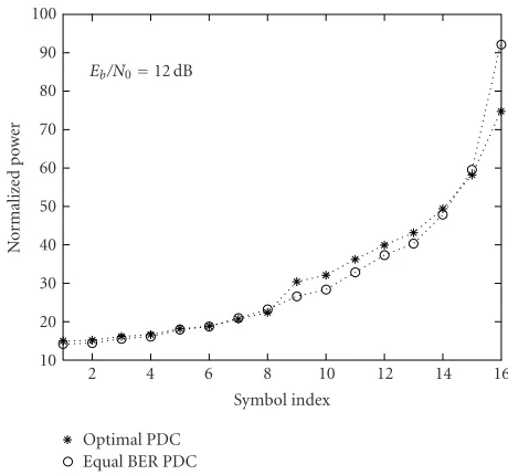
Optimal PDC Equal BER PDC
Eb/N0=12 dB
2 4 6 8 10 12 14 16
Symbol index 10
20 30 40 50 60 70 80 90 100
No
rm
al
iz
ed
p
o
w
er
Figure7: Normalized transmit power distribution (averaged over 1000 channel realizations) on 16 parallel-transmitted symbols un-der a short-term power constraint.
lation results is within 0.2–0.6 dB, which implies as argued earlier that the performance loss caused by ignoring deci-sion errors is almost negligible. The BER performances of the two sequentially detected userswith SIC is compared in Figure 6, from which conclusions similar toFigure 4can be obtained.
Optimal PDC Equal BER PDC
Eb/N0=15 dB
2 4 6 8 10 12 14 16
Symbol index 50
100 150 200 250 300 350
No
rm
al
iz
ed
p
o
w
er
Figure8: Normalized transmit power distribution (averaged over 1000 channel realizations) on 16 parallel-transmitted symbols un-der a long-term power constraint.
ZF (no SIC) ZF-SIC (no PDC) ZF-SIC (equal BER)
ZF-SIC (optimal) MF-SIC (equal BER) Target BER=10−4
2 4 6 8 10 12 14 16
Number of spreading codes 10
15 20 25 30 35
Eb
/N
0
(dB)
Figure9: RequiredEb/N0for achieving a target BER of 10−4versus
different system load under a short-term power constraint.
average Eb/N0 12 dB and 15 dB, respectively. In these two figures, larger indexes denote earlier detected symbols. For all schemes, under the chosenEb/N0, it was found that ear-lier detected symbols are allocated more power than later detected ones. However, it is interesting to note that, com-pared with the equal BER PDC, the optimal PDC allocated less power to earlier detected symbols and more to later de-tected ones. This compensates for a certain performance loss caused by underestimating the required power of later de-tected symbols with the equal BER PDC, resulting in a better performance.
ZF (no SIC) ZF-SIC (no PDC) ZF-SIC (equal BER)
ZF-SIC (optimal) MF-SIC (equal BER) Target BER=10−4
2 4 6 8 10 12 14 16
Number of spreading codes 10
15 20 25 30 35 40 45
Eb
/N
0
(dB)
Figure10: RequiredEb/N0for achieving a target BER of 10−4versus
different system load under a long-term power constraint.
In the previous figures, the performance of the fully loaded system was studied. Alternatively, in Figures9and10, the requiredEb/N0versus the number of spreading codes is shown for the short-term and long-term power constraints, respectively, at a target BER of 10−4. For simplicity in these two figures we assumed a single user with a variable number of spreading codes. When only one code is employed, the sys-tem can be looked upon as a single-user syssys-tem, while when 16 codes are employed, it is equivalent to a fully loaded sys-tem. From these results we found that, when increasing the system load, the performance of the MF-SIC with the equal BER PDC degrades very quickly. Furthermore, the ZF-SIC receiver integrated with the optimal PDC needs the smallest power, particularly under the short-term power constraint and when the system is highly loaded.
6. CONCLUSIONS
APPENDICES
A. SOLUTIONS OF KKT OPTIMALITY CONDITIONS UNDER A SHORT-TERM TRANSMIT POWER CONSTRAINT
To solve the optimization problem under a short-term power constraint we introduce Lagrange multipliers λk = [λk,1,λk,2,. . .,λk,lk]T for the inequality constraints, a can be expressed as
pe,ka2
Therefore, the KKT optimality conditions can be expressed as [18]
The third equation in (A.3) is obtained by differentiating the right side of (A.1) with respect toa2∗
k,l and setting it to zero. We note thatλ∗k,lacts as a slack variable in the third equation, so it can be eliminated, leaving
λ∗
k,l > 0, the last condition implies thata2∗
k,l = −2d−k,2lσ2ln(4ϑ∗kdk−,2lσ2). Ifϑ∗k ≥ 1/4σ2d−k,l2, then a2∗
k,l > 0 leads to a nonzero term in the parenthesis of the fourth equation which contradicts the equality, thus,a2k∗,l = 0. Therefore, we have
a2∗
Substituting this expression for a2∗
k,l into the average power constraint condition, we obtain
1 functions is monotonically decreasing with ϑ∗k, and when ϑ∗k ≥1/4σ2d−k,2l, it becomes zero, so the equation has a unique solutionϑ∗k which is readily determined. Hence, the optimal power distribution can be obtained.
B. SOLUTIONS OF KKT OPTIMALITY CONDITIONS UNDER A LONG-TERM TRANSMIT POWER CONSTRAINT
To solve the optimization problem under a long-term average power constraint, the Lagrangian is given by
La2
Similarly, the KKT optimality conditions are expressed as
After eliminating the slack variableλ∗k,lin the third equation,
With similar analysis as inAppendix A, we have
a2∗
Substituting this expression for a2∗
k,l into the average power constraint, we obtain
from which ϑ∗k can be solved.10 Hence, the optimal power distribution can be obtained.
ACKNOWLEDGMENT
This work was partially supported by NSF Grant CCR-0085846.
10To solve the integral, a summation over the ensemble of channel real-izations is used as an approximation.
REFERENCES
[1] N. Yee, J.-P. Linnartz, and G. Fettweis, “Multi-carrier CDMA in indoor wireless radio networks,” inProc. 4th IEEE In-ternational Symposium on Personal, Indoor and Mobile Ra-dio Communications (PIMRC ’93), pp. 109–113, Yokohama, Japan, September 1993.
[2] S. Hara and R. Prasad, “Overview of multicarrier CDMA,”
IEEE Commun. Mag., vol. 35, no. 12, pp. 126–133, 1997. [3] E. A. Sourour and M. Nakagawa, “Performance of
orthogo-nal multicarrier CDMA in a multipath fading channel,”IEEE Trans. Commun., vol. 44, no. 3, pp. 356–367, 1996.
[4] S. Hara and R. Prasad, “Design and performance of multi-carrier CDMA system in frequency-selective Rayleigh fading channels,”IEEE Trans. Veh. Technol., vol. 48, no. 5, pp. 1584– 1595, 1999.
[5] M. Tan and Y. Bar-Ness, “Multi-rate access schemes for wire-less multimedia MC-CDMA communications,” submitted to
IEEE Commun. Mag.,July 2003.
[6] M. Tan, P. Zong, and Y. Bar-Ness, “Multi-rate access schemes for MC-CDMA,” International Journal of Wireless Personal Communications, vol. 27, no. 2, pp. 149–182, 2003.
[7] A. J. Viterbi, “Very low rate convolution codes for maximum theoretical performance of spread-spectrum multiple-access channels,” IEEE J. Select. Areas Commun., vol. 8, no. 4, pp. 641–649, 1990.
[8] A. Duel-Hallen, “Decorrelating decision-feedback multiuser detector for synchronous code-division multiple-access chan-nel,” IEEE Trans. Commun., vol. 41, no. 2, pp. 285–290, 1993.
[9] R. M. Buehrer, “Equal BER performance in linear successive interference cancellation for CDMA systems,” IEEE Trans. Commun., vol. 49, no. 7, pp. 1250–1258, 2001.
[10] G. Mazzini, “Equal BER with successive interference cancel-lation DS-CDMA systems on AWGN and Ricean channels,” inProc. 6th IEEE International Symposium on Personal, Indoor and Mobile Radio Communications (PIMRC ’95), vol. 2, pp. 727–731, Toronto, Ontario, Canada, September 1995. [11] A. J. Goldsmith and P. P. Varaiya, “Capacity of fading channels
with channel side information,” IEEE Trans. Inform. Theory, vol. 43, no. 6, pp. 1986–1992, 1997.
[12] D. N. C. Tse and S. V. Hanly, “Multiaccess fading chan-nels. I. Polymatroid structure, optimal resource allocation and throughput capacities,” IEEE Trans. Inform. Theory, vol. 44, no. 7, pp. 2796–2815, 1998.
[13] S. V. Hanly and D. N. C. Tse, “Multiaccess fading channels. II. Delay-limited capacities,”IEEE Trans. Inform. Theory, vol. 44, no. 7, pp. 2816–2831, 1998.
[14] W. Yu and J. M. Cioffi, “FDMA capacity of Gaussian multiple-access channels with ISI,” IEEE Trans. Commun., vol. 50, no. 1, pp. 102–111, 2002.
[15] Z. Wang and G. B. Giannakis, “Wireless multicarrier commu-nications: where Fourier meets Shannon,” IEEE Signal Pro-cessing Mag., vol. 17, no. 3, pp. 29–48, 2000.
[16] W. C. Jakes Jr.,Microwave Mobile Communications, John Wi-ley & Sons, New York, NY, USA, 1974.
[17] A. Leon-Garcia, Probability and Random Processes for Electri-cal Engineering, Addison-Wesley, Reading, Mass, USA, 1994. [18] D. G. Luenberger,Optimization by Vector Space Methods, John
Wiley & Sons, New York, NY, USA, 1969.
Mizhou Tanreceived the B.S. and M.S. de-grees, both in electrical engineering, from Sichuan University, Chengdu, China, in 1993 and 1996, respectively, and a Ph.D. de-gree in electrical engineering from New Jer-sey Institute of Technology, Newark, NJ, in 2004. Currently, she is a Wireless Systems Engineer in Agere Systems, Allentown, Pa. Her research interests include multicarrier modulation systems, optimal power control
for successive interference cancellation, peak-to-average power ra-tio reducra-tion, and adaptive transmission.
Christian Ibarsreceived degrees in electri-cal engineering from Universitat Politecnica de Catalunya, Barcelona, Spain, and Politec-nico di Torino, Torino, Italy, in 1999, and a Ph.D. degree in electrical engineering from the New Jersey Institute of Technology, Newark, NJ, in 2003. Since then he has been with the Centre Tecnolo`gic de Telecomuni-cacions de Catalunya, Barcelona, Spain. His current research interests include wireless
multiuser communications, CDMA, OFDM, and interference can-cellation.
Yeheskel Bar-Ness received the B.S. and M.S. degrees in electrical engineering from the Technion, Israel, and the Ph.D. degree in applied mathematics from Brown Univer-sity, Providence, RI. He is a Distinguished Professor of electrical and computer engi-neering and Foundation Chair of Commu-nications and Signal Processing Research Center at the New Jersey Institute of Tech-nology (NJIT), Newark. He is also the