ISSN(Online) : 2319-8753 ISSN (Print) : 2347-6710
I
nternational
J
ournal of
I
nnovative
R
esearch in
S
cience,
E
ngineering and
T
echnology
(An ISO 3297: 2007 Certified Organization)
Vol. 5, Issue 12, December 2016
Mitigation of Current Harmonics in PV-APF
System Using Fuzzy Controller
Velamala Srilatha1,Guruvulu Naidu P2, Srinivasa Rao B3, V V Appalanaidu Menda4 P.G Student, Dept of EEE, Aditya Institute of Technology & Management, Tekkali, A.P, India1 Assistant Professor, Dept of EEE, Aditya Institute of Technology & Management, Tekkali, A.P, India2, 3,4
ABSTRACT: The main aim of this paper is to compensate current harmonics in PV-APF system using Fuzzy Logic
Controller. A 3-Ф, 3-wire system is proposed in this paper which consists of PV system, a dc/dc converter which is controlled by MPPT, three phase VSC to act as APF and Non-Linear Load. The main theme of this INC MPPT is to efficiency from the PV system. For reliable performance of active power filter and better harmonic compensation this paper proposes a concept of instantaneous power theory. Also, a comparison analysis is performed for improving THD by PI/Fuzzy controllers. This system is experimentally verified and tested using Simulink.
KEYWORDS: Harmonic Current, Total Harmonic Distortion, PV system, Power Quality.
I. INTRODUCTION
In the present scenario, power quality and power supply are the main problems in power system. So that, the DG systems has got lot of importance because of the limitation of conventional power generation. The main advantage of DG system, it is more productive, high quality, and provides power to loads to maintain continuous administration. Therefore, the PV system is considered as an infinite, uncontaminated alternative resource [1]. In PV systems, there is a possibility to convert direct sun energy to electrical energy without any interruptions. The efficiency of the solar system can be improved by using general MPPTs. The frequently used MPP techniques are given below:
1. P&O Technique. 2. INC Technique.
3. Fuzzy based MPPT Technique.
The maximum utilization of power electronic systems can produce nonlinearity in network, and its effects on overall system performance. To mitigate problems caused by harmonics, some filter components are used inside the system.
Generally, passive filter is a solution to reduce the harmonics. But these passive filters are responsible for resonance type problems occurred in grid. So that, active power filter is the better solution as compared to general filters for compensating harmonics.
In this paper, PV-APF [2] system is proposed which produces an UPF supply to utility and non-harmonic current to the loads.
A. STRUCTURE OF PV-APF SYSTEM:
Figure 1. Configuration of Proposed Grid Connected PV-APF System
B. PHOTOVOLTAIC ARRAY MODELING:
In the PV network of electrical phenomenon, cell is the necessary part. For the raise in appropriate current, high power and potential difference, the sunlight dependent cells and their region unit joined in non-current or parallel fashion called as PV exhibit are used [3]. In practical applications, each and every cell is similar to diode with the intersection designed by the semiconductor material. When the light weight is absorbed by the electrical marvel sway at the point of intersection, it gives the streams at once. The (current-voltage) and (Power-Voltage) attributes at absolutely unpredictable star intensities of the PV exhibit are represented in Figure 3, whereas the often seen existence of most electrical outlet on each yield is shown in power diagram 2.
I = Iph – ID -Ish (1) I=Iph –Io [exp (q V D / nKT)] – (vD /RS) (2)
ISSN(Online) : 2319-8753 ISSN (Print) : 2347-6710
I
nternational
J
ournal of
I
nnovative
R
esearch in
S
cience,
E
ngineering and
T
echnology
(An ISO 3297: 2007 Certified Organization)
Vol. 5, Issue 12, December 2016
Solar cell output power is given as the product of V and I
Figure 3: Response of output characteristics of PV Array
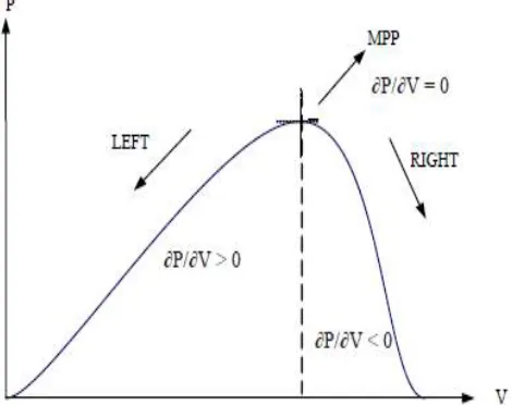
C. INC MPPT TECHNIQUE:
The disadvantage of perturb and observe method to track the peak power under fast varying atmospheric condition is overcome by IC method. The IC can determine that the MPPT has reached the MPP and stop perturbing the operating point. If this condition is not met, the direction in which the MPPT operating point must be perturbed can be calculated using the relationship between dl/dV and –I/V. This relationship is derived from the fact that dP/dV is negative when the MPPT is to the right of the MPP and positive when it is to the left of the MPP [4]. This algorithm has advantages over P&O in that it can determine when the MPPT has reached the MPP, where P&O oscillates around the MPP. Also, incremental conductance can track rapidly increasing and decreasing irradiance conditions with higher accuracy than P and O. In this technique the change of PV voltage can be obtained with respect to MPP voltage peak power. Figure 4 shows the PV power curve for incremental conductance method.
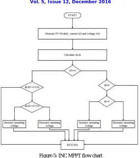
Figure 5: INC MPPT flow chart
The power expression,
P = V ∗ I (3) Differentiate the power equation with PV terminal voltage,
v
VI
v
p
(
)
(4)
At MPP,
0
v
p
(5)
The modified equation expressed as:
V
I
V
I
(6)
This MPPT technique controls PWM signal for boost converter until (dI/dV) + (I/V) = 0 is obtained. Figure 5 shows the INC MPPT flow chart [5].
D. P-Q THEORY FOR REFERENCE CURRENT GENERATION:
ISSN(Online) : 2319-8753 ISSN (Print) : 2347-6710
I
nternational
J
ournal of
I
nnovative
R
esearch in
S
cience,
E
ngineering and
T
echnology
(An ISO 3297: 2007 Certified Organization)
Vol. 5, Issue 12, December 2016
[6]-[7]. The instantaneous active and reactive powers of load current and voltages can be obtained by using Clark’s transformation technique.
)
8
(
2
/
3
5
.
0
2
/
3
5
.
0
0
1
3
2
)
7
(
2
/
3
5
.
0
2
/
3
5
.
0
0
1
3
2
^ ^
c b a a c b a aI
I
I
a
I
I
V
V
V
a
V
V
^ * * *2
/
3
2
/
3
0
5
.
0
5
.
0
1
3
2
a
i
i
i
i
i
a c b a (9)II. PI CONTROLLER
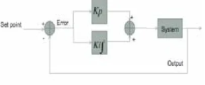
PI controller will eliminate forced oscillations and steady state error resulting in operation of on-off controller and P controller respectively [8]. However, introducing integral mode has a negative effect on speed of the response and overall stability of the system.
Figure 6: Configuration of PI controller
Thus, PI controller will not increase the speed of response. It can be expected since PI controller does not have means to predict what will happen with the error in near future. This problem can be solved by introducing derivative mode which has ability to predict what will happen with the error in near future and thus to decrease a reaction time of the controller.
III. FUZZY LOGIC CONTROLLER
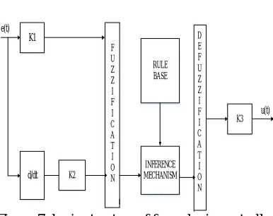
In the previous section, control strategy based on PI controller is discussed. But in case of PI controller, it has high settling time and has large steady state error. In order to rectify this problem, this paper proposes the application of a fuzzy controller shown in Figure 7 [9]. Generally, the FLC is one of the most important software based technique in adaptive methods.
As compared with previous controllers, the FLC has low settling time, low steady state errors. The operation of fuzzy controller can be explained in four steps.
K1
d/dt K2
K3 F
U Z Z I F I C A T I O N
RULE BASE
INFERENCE MECHANISM
e(t)
u(t)
D E F U Z Z I F I C A T I O N
Figure 7: basic structure of fuzzy logic controller
In this paper, the membership function is considered as a type in triangular membership function and method for defuzzification is considered as centroid. The error which is obtained from the comparison of reference and actual values is given to fuzzy inference engine. The input variables such as error and error rate are expressed in terms of fuzzy set with the linguistic terms VN, N, Z, P, and Pin this type of mamdani fuzzy inference system the linguistic terms are expressed using triangular membership functions. In this paper, single input and single output fuzzy inference system is considered. The number of linguistic variables for input and output is assumed as 3.The numbers of rules are formed as 9. The input for the fuzzy system is represented as error of PI controller. The fuzzy rules are obtained with if-then statements. The given fuzzy inference system is a combination of single input and single output. This input is related with the logical operator AND/OR operators. AND logic gives the output as minimum value of the input and OR logic produces the output as maximum value of input.
IV. SIMULATION DIAGRAM AND RESULTS
The proposed hybrid system shown in Figure 1 [10] can be verified using Matlab/Simulink.
The complete system can be simulated for the period of 0.75 sec and this can be divided into following sections. i.e, the period 0.05 to 0.35sec relates to current controlled VSC converter, between the periods 0.35 to 0.5sec relates to MPPT based current controlled VSC converter, between the periods 0.5 to 0.6sec is PV-APF mode and finally, 0.6 to 0.7sec is APF mode.
Case 1: With PI Controller.
ISSN(Online) : 2319-8753 ISSN (Print) : 2347-6710
I
nternational
J
ournal of
I
nnovative
R
esearch in
S
cience,
E
ngineering and
T
echnology
(An ISO 3297: 2007 Certified Organization)
Vol. 5, Issue 12, December 2016
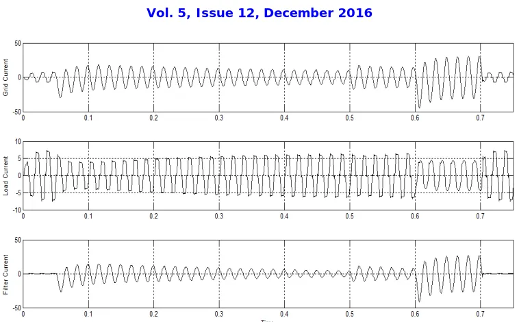
Figure 8:Waveforms for (a) Source Current. (b) Non-Linear Load current. (c) APF current with PI controller
Figure 8 shows the simulation result for (a) grid current, (b) load current and (c) filter current. As we know, because of non-linear load presence in the system the load current is effected by unwanted harmonics. In order to compensate this problem a PV-APF is proposed under three cases as explained above and the filter grid current is also shown.
Case 2: With Fuzzy Controller
In this case the proposed system can be simulated using Fuzzy controller instead of conventional PI controller for compensating the current harmonics. The performance results for this proposed system and its total harmonic distortions are shown below.
Figure 9 shows the simulation results of (a) grid current, (b) load current and (c) filter current. As we know, because of non-linear load presence in the system the load current is effected by unwanted harmonics. In order to compensate these problem a Fuzzy based PV-APF is proposed under three cases as explained above and the filter grid current is also shown. And the comparison of total harmonic distortion for the two cases such as PI and Fuzzy controller is formulated in table.
Table 1: %THDs Evaluation
Table 1 shows the comparison of Total Harmonic Distortion for filtered utility current under two different cases such as (a) Conventional PI controller and (b) Fuzzy Logic Controller. From the above analysis the proposed system with Fuzzy Controller gives better THD as compared with Conventional PI controller.
V. CONCLUSION
This paper proposed concept of PV based active power filter for power quality improvement using instantaneous power theory controller. This controller can be implemented for two purposes i.e, one for to supply power from PV system and other one is for filtering the harmonics caused by non-linear load. In this paper PI, Fuzzy Controllers are developed for controlling Dc link voltage. The performance of this system can be tested and verified in Matlab/Simulink. From the results we conclude that, Fuzzy Logic Controller shows better performance over conventional controller.
REFERENCES
[1] Villalva MG, Gazoli JR, Filho ER. Comprehensive approach to modeling and simulation of photovoltaic arrays. IEEE Trans Power Electron. 2009; 24(5):1198–208.
[2] Tuyen, Nguyen Duc, and Goro Fujita. "PV Active Power Filter Combination Supplies Power to Nonlinear Load and Compensates Utility Current", IEEE Power and Energy Technology Systems Journal, 2015.
[3] Kuo YC, Liang TJ, Chen JF. Novel maximum-power-point tracking controller for photovoltaic energy conversion sys¬tem. IEEE Trans Ind Electron. 2001; 48(3):594–601.
[4] Houssamo I, Locment F, Sechilariu M. Experimental anal¬ysis of impact of MPPT methods on energy efficiency for photovoltaic power systems. Int J Elect Power Energy Syst. 2013; 46:98–107.
[5] Tuyen ND, Fujita G. PV-active power filter combination supplies power to nonlinear load and compensates util¬ity current. IEEE Power and Energy Technology Systems Journal. 2015; 2(1):32–42.
[6] Rezvani F, Mozafari B, Faghihi F. Power quality analysis for photovoltaic system considering unbalanced voltage. Indian Journal of Science and Technology. 2015 Jul; 8(14):1–7.
[7] Kanth KM, Kishore RD. Implementation of MPPT tech¬niques for a high step-up converter with voltage multiplier module based photovoltaic system. Indian Journal of Science and Technology. 2015 Sep; 8(23):1–6.
[8] Das JC. Passive filters-potentialities and limitations. IEEE Trans Ind Appli. 2004; 40(1):232–41. [9] Akagi H. Active harmonic filters. Proc IEEE. 2005; 93(12):2128–41.
[10] Akagi H, Kanagawa Y, Nabae A. Generalized theory of the instantaneous reactive power in three-phase circuits. Proc Int Conf Power Electron; Tokyo, Japan. 1983. p. 1375–86.
Modes→
Type↓ d-q Current
(0.07S)
PV-APF (0.55S)
APF (0.68S)
Utility (0.72S)