STRUCTURAL EVALUATIONS FOR REACTOR BUILDING CRANE
UPGRADE
Arun C. Pal, P. E. Entergy Nuclear N o ~ James A. FitzPatrick NPP P.O. Box 110
Lycoming, N.Y. 13093
ABSTRACT
During the proceu of upgrading the reactor building crane to "single faihtre Woof' status it w u digovered that analyzing the e x i ~ bridge girder with .pplkmioe of ten,ion-field method could avoid co.tly modifiuttimu. Also, modeling the entire supporting structure and crane girders together, which is more realistic anyway, instead of modeling and analyzing them separately avoided costly moditi~ttions at the column bases, l~ne total saving is estimated to be $1.OM and all regulatory requirements and codes and standards were met.
INTRODUCTION
The DOE is not ready for accepting spent nuclear fuels from operating nuclew power plants within the next decade, although originally it w u supposed to have done so from 1995. ~ f o r e , all plants planning decommissioning and/or life extension have to remove and store spent fuel in dry s u n g e casks on site, since the spent fuel pools were not built for the capacities required. These casks must be handled per NURF~ 0612; i.e., either the crmles must be upilrKled to "single- failure-proof' per NUREG 0554 or, a load drop analysis must be performed to show that no safety related equipment is damaged by the failed load. At the James A. FitzPutrkk Nuclear Power Plant OAF), it was decided that upgrading the ReacWr Building Crane to "single-failure-woof' i.e., faihue of any single cCmtlmttent would not result in a total failure of the load handling system, can achieve the objective. Please note that the rated capacity of the crane, 125 Tons will remain the s a m e .
A preliminary evaluation showed that the entire trolley had to be r e p ~ The r e p ~ e n t trolley was designed by EDERER In¢, Seattle, Washington; with its XSAM (extra safety and monitoring) feaau~. EDERER submitted a generic Topical Report to the USNRC and received Safety Evaluation Report from the NRC in 1983.1'he SER conchuled that the XSAM trolley meets the NUREG 0554 requirements in general; but site-q~~c m~ses must be performed on remainder of the crane system e.g., the bridge girders and the building column or support structure etc, and must be upgraded, if required.
The original crane was p r o ~ r ~ in early 1970s and was designed per EOCI-61 and USAS B.30.2-1967. In response to NUREG-0612, it was evaluated to the codes a p p ~ l e at the time e.g., CMAA-70 mul ANSI B30.2, 1976 and was found to meet the requirements of both. However, the Wcgurement specification for the Reactor Building Crane Upgrade project required that" Design, Analysis,
Fatx'icAtlon,.
Inspection,
Testing, Quality Assurance and Handl/n8 shall be perfmmed in accordance with requirements of ANSl/ASME NOG-I (latest revision)" [I], with some minor exceptions. SECHON NOG- 4000: Requirements for Structural Components, provides detailed procedure for analysis of the crane. For example:Loads:
Dead Loads (trolley and bridge load); Live Loads (rated load, critical load, conmuction load, credible critical load); Impact toed (vertical, transverse horizontal and lonsitud/nal horizmtal); Wind Load (operating wind, design wind and tornado wind); Nmmal Plant Operating Loads ( p i e opemticm induced load and static test p r e m ~ loads) and Seismic and Abnormal Events ~ (Design Basis or Safe Shutdown Earthquake, Operating Basis Earthquake and Almmmal events like plant equipment failure loads) are the loads to be considered.
Load Combinations:
Please refer to NOG-4140: LOAD COMBINATIONS, for the prescn1~d load combinations to be considered.
Seismic Analysis:
NOG-I requires a generalized three dimensional mathematical modeling of the crane with finite elements and response specman or time-history analysis for the seismic inputs applied at crane rail from the plant data. Location and number of dynamic degrees of freedom, boundary conditions at trolley and the crane rails, damping values to be used and the decoupling criteria for the crane rails are very well defined for the analysts. Please refer to NOG-4150 thru 4154 for the details.
INITIAL ANALYSIS
The initial structural analysis was performed by NORPAC Engineering for the EDERER Corp [2].
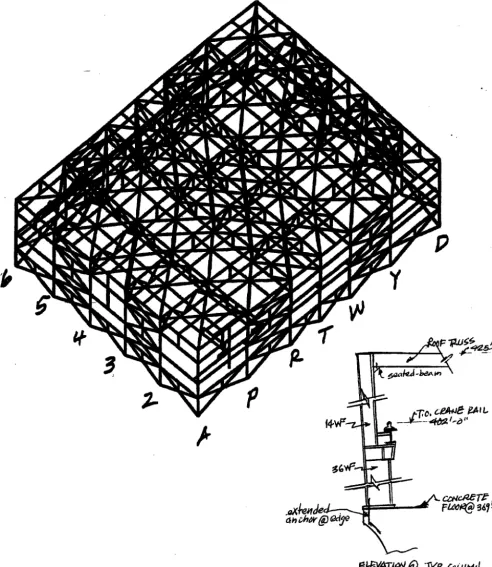
"I'ne crane trolley runs on a two.girder bridge at 21'0" apart, with a span of 116'11". The girders m'e attached by flex]'ole end-ties at the ends. The bridge rails are supported on runway beams (bracket-type beam seat) attached to the top of W36X280 building columns. The crane members were modeled as 3-dimensimal beam elements with the hoist rope modeled as a very flexible beam with proper cross sectional area and modulus of elasticity. Modeling and member releases are done in accordance with NOG.
The response spectra at JAF consist of 0.5% damping OBE and 1% damping DBE, with peaks broadened +/- 15% to account for inaccuracies. Since NOG allows use of 4% damping for OBE end 7% for DBE, the response spectra were converted to these damping values using the formula:
A, fA00, * (0.01/n) m
Where, A, is the modified peak response; A0m is the peak response at 1% damping and n is the appropriate damping value.
Also, response spectra were available for column base el. of 369'0" and top of the columns at el. 425'0", whereas the crane rails are supported at el. 402'0". A linear interpolation was used to determine the responses at el. 402'0". It was observed that for both horizontal and vertical directions, the 4% damped OBE spectra values exceeded the 7% damped DBE valua and therefore the OBE was used for analysis.
Crane runway was inchtded in the crane analysis model, resuained for all six degrees of freedom by springs located at each of the ~ d i n g columns. NOG provides coupling/decoupling criteria for crane analysis.
The building Mructure which supports the crane was modeled including columns, end walls, side walls, roof truss and other roof framing members for the walls and the roof. Runway ~ were not inchtded in the model since they were included in the crane model.
Mathematical model was developed in conformance with NOG. In Figure-I below just the Trolley Model is shown
for illustration. C ~ ~ ° ~ w ~ 7 ~ ~
• ~ ; TC.o~c.E'r" /ST ~w~)-~gmd
,o
Loading Conditions:
Four bridge positions were used for analysis; e.g., • bridge at end approach
• bridge with a set of wheel trucks mid-span between the two end columns • bridge on top of intermediate cohnnns
• bridge on center span of the building
These locations were chosen for maximizing the runway and building column loading and also for maximum crane response. Also, three trolley positions were considered for each of the bridge locations descn'bed above; e.g.,
• trolley at end approach
• trolley with the midpoint between the heavily loaded wheels end the trolley load girt centered at girder ¼ point
• trolley with the midpoint between the heavily loaded wheels and the trolley load girt centered at girder mid-span
High hook and low hook positions were considered for each loading condition. All requirements are in accordance with NOG. The pendulum effect was determined to be negligt~ole. The computer program used was IMAGES-3D Version 2.0 by Robert L. Cloud and Associates.
Mathematical Analysis:
N O G allows mathematical analysis using either response speclmm or time history methodology. The response spectrum
analysis for a lumped mass, multiple-degrees-of-freedom system was carried out. The basic equation of motion used was:
{ x } = {o}
V~lere:
[K] = stiffness matrix; g= acceleration due to gravity; w ~- eigenvalue ; [W]= weight matrix; {X}=eigenvector (mode shape) and {0 }= null vectef
Weights were frmn available data of the crane and new trolley. Natural frequencies, mode shapes and participation f a ~ n were calculated from modal
analysts.
1"he NRC 10% rule for closely spaced modes was appfled. Once the frequencies and mode shapes were detennim~ s e i m ~ analysis was perfmmed. Three-dimemimal input response spectra appfied and generalized displacA, ments and accelcntiom were calculated. From the generalized results, the individual and combined modal d i ~ ~ e n m and gceleratiota were calculated, l~e three components o f earthquake motion were combined by ~aare-root-of-the mun-of Kluares (SRSS) method.Results of Analysis:
The analysis showed that the maximum response w u with the hook at high position, the bridge at the end approach and the trolley at mid-span. Similar results also found parallel to the runway. Member stresses were obtained by combing the s t a t i c load case with the seismic stresses for accelerations in all three directions, l~ne following recommendations were made from the ~ of the initial analysis:
• The end ties joining the bridge girders needed to be redesigned due to severe overstress. It required a
pinned
connection in the horizontal direction for the girders to deflect relatively independently but must be able to uury the moment about the vertical axis. 1"his design change was perfmmed since the top-of-the-rails elevations m y vary somewhat.
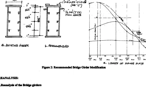
• The box bridge girders (108" X 42" and span of 116'-11" ) were overstressed and required stiffeners on flange and the web. Flange plates (2 plates l"thickX6" wide) had to be extended 25'0' on either side from the center span to reach an allowable stress limit per AISC (see Figure-2). This recommendation was not accepted, since "tension-field-action" was not considered.
• Although the misses in the columns were acceptable, the cohann anchor bolts stresses exceeded the AISC allowable limits when the crane was located over the cohmm. 1,his recommendation needed reevaluation, since the required modification was cost proln itive and cumbersome.
~ - ! - -
~,~ i
, o
• i ~
O0 ~ z .
• J
i
" I
I
I
I
I _ , ' l1,~" ~
~~~r "~"
Figure 2: Recommaded BridlP Oirda" Modification
~ A I . , Y S I S :
t . n m u n 3 ~ ot tie nddse
8/rdm
/
. ~ mud ~ the ~ Sirdm wen rommbn~ m P ' b ~ tmmim ~kn z a m . From Amc NimS Ediam, [3], - Unh'ke co]ram, whtds ~ nre m tin v a ~ of c o l l q ~ u d n k tmddi~ mqp JJ q~uecbed, the panlJ of' the plate girder web, bmmd~ m 811 aid~ by the f~kdw f b n f p ar ~ ~ ml cspebb of c m y ~ g bads ~ h ~ of their "web bucklb~" Ioed." The m~'men must be able to tact u umqmm/on ~ This is malosmn to a puel of' a Pratt truss; Le., a ~ strip of the web 8cts u a tmsioa member wldle the trm~ene J ~ m e n tact u compression memben. 'I'ne maximum besdk~ Weu , ~ l ~ b d ~ WSS 27.3 ksi
(=1.35X Fb';
the factm" 1.33 is q~licmble shsce seismic loedJng is conskkmi) m l tbo ~ u m web diner Wew w u 13.1 ksLmd~lJ avoided the ~
~
dm:rn~ under ~
~
and rived ~ 1 ~
S400,O00.O0.
2. Remud35b of' tin nuUdinll Structure:
The W p a / a i n u ofthe o v a m m s in ~ bolt w u the modeling c o m i d n t i o n thmt colmnns ere fixed st the base. Due to the unavm/labi~ of o d ~ a l d . ~ ~ _~~om_ this was the ~ ~ which resulted in ~ bolt ova'stress. However the t n , d - ~ of the mJdtm" bolts ms extmufed base plate was even fbrdnr ~ tusk.
The steel columns at the re6ml floor are on the edge of'the cmscmW flora' multo instull mine mtdux bolts would require base plate eztmsims in one clkection only - into the inner side of the floor. Thus base plst~ would be ecceatric and c o h n n lomb must be mmsfemd to the base p l ~ by ushq bnwJcm. 'lhe other problem w u Iocath~ the mtdxr bolts m miss rebarL 3he cost eJtfaum run to tppm:bsuzely SSOo, o00.O0. Thui. ~ mm]ysis was m ~ a . ~ . ANAIY.CH Cmuulti~
~ e a a
~
~ reuah~ [4]. The prosmm umd wu XnXQUS.
• Unlike tho JnJtJld 8mlyl~. ~ llld ~ WlKe ~ ill 8 ~ m ~ l model
• Bemn elemmts were used Far the t l n e _ _dj~mtimulflnile elmnmt model Fur response mpeclrtms 8nsl~is
•
c r m ma m,n pm un
mnuU=
.m
ran= u nx =u
u.n u
• Column bwe plaUlm wilh two bolln wwe ,uuddared p t u ~ in bmb ~ dlnmdmL ~ p ~ ~ ~ bolU were modeled with roumTumd m/ffnmn b u d o n base pine amadyoim p a h m e d m d t a .
• Runwsy ~ k d m were cmnecmd m the ~ column wi~ ~ offset end such t h e all u u ~ s ~ m M ~ ~ ~ e j o m t
P
12.
T"
P
Y
__~e. c 2 , ~ " ~,~ t,
- . . ~ t.. D,'
Results of the Reanalysis:
Results of the response spectnan analysis for member loads and joint forces were used for AISC design checks. The following are the resulta ofthis reanalysis effort:
• Column base plates end anchor bolts are adequate for the imposed loading. The stresses were well within allowables per AISC codes.
• All steel members including the Reactor Building roofWau and the upgraded crane are qualified
• The bolted connection of the lower chord of the roof m m to the column is ovemressed at the column line
where the crane is positioned when the seismic event o¢cm. Ynis is clearly a localized condition, which could result in a localized plastic deformation without affecting the slructural integrity of the bt~ding.
CONCLUSIONS:
• Code compliance and meeting the regulatory requirement, are very i m p m ~ t st an operating nuclear power plant; however a p p H ~ o n current analytical methodology within the botmds of these must be carefully evaluated prior to recommending ,my moditkmiom. The bridge girder ,/iffeni~ w u not required.
• Safety and dose expmme to imgallaflon crew also must be comidered for m ~ at operating planm. • Engineers employed at operating nuclear power plants must keep up-to-date with the profession so that they
can adequately e v ~ the w o t ~ done for them by outside A/Es and oommltants, l~nme not attw~ed to an operating plant are completely tmaware of the modification requirement, and do sometimes recommend the design change that appears best in the analysis; e.g., the crane company reccmtmended replar, ement of 5/8" ASTM -A325 bolts with 7/8" since that worked. However this would have required lead paint removal, drilling bigger holes and replacing them, all work requiring high gaffolds and working in the reactef building. So we asked for a reevaluation with A490 bolts and that wmkecL
• Practical decision making is very essential under some ¢irmanstancu e.g., coincidence of cask lumdling (a two week period in two years time), ~ g u r r l m t ¢gcurrence of an earthquake equivalent to the plant design basis
earthquake (with a probability of I in 50 to htmdred yean) end the crme located directly over a ¢ohmm during etat period (mot earthquake..re of 15 .ecmd or let. dumtm) i. l n a k a l l y of extremely low probebility.
Calculated mpwoximate wobability <104 and so not crech'ble per NRC. However, there will be an open item under the cask handling project to check the roof truss bottom chord bolts if there is an earthquake during the process of lifting or lowering the casks.
REFERENCES:
[ 1 ] ASME NOG-1-1995: RULES FOR Construction of Overhead and Gantry Cranes (Top Running Bridge, Multiple Girder
[2] Conn~her, N., NORPAC Engineering Inc, Seattle, Washington; New York Power Authority, James A. FitzPatrick NPP, Reactor Betiding Crane Seismic Analysis, January 2000.
[3] AISC (American ~ of Steel Construction): Manual of Steel Construction, Ninth Edition, October 1994