Effect of Vertical Accelerations on Dry Storage Cask Seismic Performance
Sharad Dangol1 and Luis Ibarra2
1 Graduate student, Dept. of Civil and Environmental Engineering, University of Utah, SLC, UT. USA. 2 Assistant professor, Dept. of Civil and Environmental Engineering, University of Utah, SLC, UT. USA.
ABSTRACT
This study evaluates the effect of vertical accelerations on the seismic performance of free-standing dry storage casks (DSCs). DSCs store spent nuclear fuel at sites contiguous to nuclear power plants (NPPs), known as Interim Spent Fuel Storage Installations (ISFSIs). Numerical seismic analyses of ISFSIs are usually performed for 20-year compliance periods, but the suspension of the licensing process of the Yucca Mountain geologic repository has triggered a reevaluation of DSCs as a potential mid-term solution for hundreds of years. Longer-term operating periods will lead to i) very large horizontal accelerations, ii) destabilizing effects of vertical accelerations, and iii) aging material deterioration. The first two factors affect the overall seismic performance of DSCs, potentially leading to casks tipping over and sliding, impacting the concrete pad or adjacent casks. This part of the study assesses whether vertical seismic accelerations may lead to structural instability of freestanding DSCs. Numerical evaluations of the cask-concrete pad system are used for the first phase of the study.
INTRODUCTION
This study is part of a research project that is evaluating the mechanical performance of dry storage casks (DSCs) under seismic loading for long-term operational periods. The spent fuel at nuclear power plants (NPPs) is initially stored in pools for at least five years to control the temperature of the fuel assemblies, and prevent melting of their cladding. Thereafter, the spent fuel is transferred to DSCs at sites contiguous to the plant, known as Interim Spent Fuel Storage Installations (ISFSIs). The regulations for these storage systems (10 CFR 72) are designed to ensure adequate passive heat removal and radiation shielding during normal operations, off-normal events, and accident scenarios.
(a) (b)
Figure 1 ISFSI Facilities. (a) Freestanding DSCs on a Concrete Pad, (b) Horizontal DSC in a Concrete Vault (Tripathi and Hall 2007).
Numerical seismic analyses of ISFSIs are usually performed assuming a compliance period of 20 years. The consideration of DSCs for storing spent fuel for hundreds of years has created new challenges that have only recently started to be addressed. In the case of seismic hazard, longer-term operating periods result in i) very large horizontal accelerations, ii) destabilizing effects of vertical accelerations, and iii) aging material deterioration. The first two factors affect the overall seismic performance of DSCs, whereas material degradation reduces the capacity of the casks. Therefore, the numerical simulations will consider coupled effects of mechanical stresses due to seismic events and aging material degradation of cladding and containers.
Large earthquakes can cause casks to tip over, impacting the concrete pad or adjacent casks. The casks may also slide and collide with other casks or structural components. The integrity of the DSCs is important, even if the overpack does not breach, because eventually the spent fuel-rods need to be shipped either to a reprocessing plant or a repository. The ability of transporting spent fuel after more than a century of storage will require an understanding of the condition of the spent fuel and storage canisters (Kadak and Yost 2010).
The main goal of this study is to evaluate the long-term seismic performance of freestanding and anchored DSCs using experimental tests on a shaking table, as well as comprehensive numerical evaluations that include the cask-pad-soil system. This paper covers the initial numerical simulations of freestanding casks.
Previous Numerical Simulation Studies
Numerical analyses of DSCs have provided different results in terms of threshold accelerations for tip over. Luk et al (2005) assessed the performance of casks considering the cask-pad-soil system, and found that tip over is influenced by the frequency content of the record, the cask geometry, and the friction between steel and concrete. They recorded tip over cases for horizontal peak ground accelerations (PGAs) as low as 0.6 g’s. They considered soil-structure interaction (SSI), but the rigid pads caused earlier tip overs. Recently, Ko et. al (2009) performed a more limited study of Taiwanese storage casks including SSI effects. They subjected the casks to horizontal accelerations of about 1.3 g, but the casks did not rock enough to tip over.
DSCs Selection
The DCS main physical characteristics will be based on Nuclear Regulatory Commission (NRC) list of approved casks. The DSCs can be divided into i) bare-fuel dry-storage, and ii) canister based systems. In bare-fuel cask systems, fuel-rod assemblies are placed in a vertical position directly into a fuel basket integrated into the cask. The basket supports the fuel assemblies and fixed neutron absorbers for criticality control. In the case of canister-based storage systems, spent-fuel assemblies are placed into baskets integrated into a thin-wall stainless steel cylinder (Figure 2). This cylinder is usually called multi-purpose canister (MPC), although it only has two functions: store and transport spent fuel1. Most
canister-based systems also are designed for vertical storage, such as Holtec International HI-STORM 100. This cask includes a MPC contained within a steel-concrete-steel overpack. NAC has also developed vertical storage systems based on the MPC concept (Figure 1a). The MPC in all these casks is a welded pressure vessel that needs to meet ASME Section III, Subsection NB (ASME 2004) requirements. The welds need to ensure the integrity of the canister to prevent helium leaks. Note that the MPC can be designed to freely move inside the overpack when a seismic event occurs. In these cases, the stresses and strains developed in the fuel basket and spent-fuel rods due to the mechanical interaction of MPC and overpacks need to be evaluated. Finally, the NUHOMS HSM system is an available DSC that can be stored horizontally in a concrete module or vault.
Figure 2 HI-STORM 100 Overpack and Canister (Shah et. al, 2003)
Modern DSCs hold about 10-18 metric tons of used fuel, which is equivalent to about 24-32 pressurized water reactor (PWR) fuel assemblies or 56-68 boiling water reactor (BWR) fuel assemblies. The casks are about 18-20 ft in height, 8-10 feet in diameter. The cask walls can be over 2-feet thick, and usually consist of two stainless steel rings. In terms of seismic performance evaluation, one of the most significant DSC features is the radius-to-height of center of gravity ratio ( / ), or cask aspect ratio. This parameter ranges from 0.43 to 0.68 in NRC’s list (USNRC 2013).
For freestanding and anchored cask simulations, one cask will be selected for aspect ratios corresponding to lower, middle, and upper bound values. Tentatively, the bare-fuel cask Transnuclear TN-68 will be selected for low cask aspect ratios ( / = 0.44). For intermediate ratios, the common canister-based casks HI-STORM 100 is likely to be used ( / 0.56). The cask BNFL Fuel Solutions WSNF-223 may be used for the case of high aspect ratios ( / 0.68). The above selections would
1
cover not only the spectrum of aspect ratios, but also different vendors, as well as bare-fuel and metal canister casks. For casks stored in a vault, the Transnuclear West module-cask NUHOMS may be considered.
Ground motion selection
In the US, the ground motions used to evaluate DSCs need to meet 10 CRF 72 requirements. 10 CFR §72.103(f)(2)(i) requires the use of earthquake ground motions characterized by horizontal and vertical free-field ground motion response spectra at the free ground surface. It also indicates that uncertainties must be addressed through probabilistic seismic hazard analysis (PSHA) or suitable sensitivity analyses. These objectives can be accomplished by applying Regulatory Guide 3.73 (USNRC 2003), which specifies a PSHA to obtain the ground motion characteristics and response spectra for DSCs. This guidance will be followed after taking into account that the probability of occurrence of a given seismic event increases as the operating period is extended, which increases the accelerations at the site.
Horizontal accelerations: For a 20-year compliance period, ISFSIs are usually designed for a Design Bases Earthquake (DBE) associated to a return period, 2,000 years (i.e., SECY-98-071 1998), corresponding to a probability of exceedance 1/ 5 × 10⁻⁴/year. To obtain the probability of
exceeding the DBE in 20 years (probability of occurrence), a Poisson distribution can be used to obtain (Benjamin and Cornell 1970).
0 1 0 1 (1)
In Eqn. (1), is time in years, and is the expected number of occurrences in a given interval. Then, the probability of exceeding the DBE [ 0 ] in 20 years is 1%. To obtain the same probability of occurrence of 1% in 300 years, Eqn. (1) indicates that a return period 29,850 years needs to be considered in the calculations ( 3.3 × 10⁻⁵/year). This longer return period is associated with larger ground motion accelerations, which will result in PGAs larger than 1 g for a large number of NPP sites. Moreover, larger ground motions are correlated to longer duration times, which increases the likelihood of tip over or collision during the event.
Thus, it is also important to consider sets of ground motions representative of Western and CEUS sites for large seismic events. The different ground motion sets should include far field motions and near fault ground motions. A set of long duration ground motions is needed to properly assess global instability.
Figure 3 Median V/H ratios for vertical strike-slip earthquakes at soil sites (a) 5 km from the fault, and (b) 30 km from the fault (Gülerce and Abrahamson 2011).
Concrete Pads
Relatively thin concrete pads have been used in most ISFSIs with a thickness ranging from 0.61 to 0.91 m [2 to 3 ft]. The pad thickness is usually controlled by design limitations related to cask impacts. That is, the cask and MPC performance in a tip-over event depends on impact energy absorbed by the concrete-pad foundation system (Shah et. al 2003). The concrete-pads are flexible slabs because they can be over 100 m [328 ft] in length, and out-of-plane flexibility may be relevant (Bjorkman et. al 2001). The RC pads will be dimensioned based on the ultimate strength design method (ACI 349-06 2006). The steel-concrete friction coefficient has been estimated to range from 0.2 to 0.72, although for the cask-pad system the most likely value for this parameter ranges from 0.5 to 0.7 (Ko et. al 2009, Shirai et. al 2008). The friction coefficient usually determines whether casks exhibit sliding or rocking (Luk et. al 2005). Based on the cask configuration of Figure 4, it can be seen that based on static equilibrium, sliding occurs when the horizontal seismic force exceeds the friction force:
, which leads to (2)
And tip over takes place when the stabilizing moment at point 0 is smaller than the moment created by the horizontal force at point 0:
, rendering (3)
where is the cask radius. For the static case, tipping occurs when Eqn. (3) is satisfied and r/h . For example, the HI-STORM 100 has r/h 0.56 and, tipping occur when, 0.56. Tipping will occur if at a given time the term is larger than 0.56. Then, the relationship at a given time between the horizontal and vertical accelerations determines in larger part whether a cask tips over or slides. Therefore, DSCs response under seismic loading is highly influenced by the frequency content of the record, and
intercomponent variability among the three directions of motion.
0
DSCs failure modes
The global stability analysis is needed for licensing DSCs, given that NRC requires to demonstrate that the fuel is easily retrievable, and satisfy three performance objectives: i) fuel-rod integrity, ii) fuel assembly geometric arrangement, and iii) canister integrity. Fuel-rod integrity means no significant numbers of individual fuel rods suffer a “gross breach”. Fuel assembly geometric arrangement refers to maintaining the original geometric arrangement of fuel assemblies and lifting points as when they were placed into dry storage, including shielding and neutron absorbing materials. Canister integrity means neither metal canisters nor bare casks will be breached to allow the release of helium and air ingress. As observed, 10 CFR 72 not only requires that the doses from used fuel are less than prescribed limits, but also that the fuel can be retrieved without the release of radioactive material to the environment [10 CFR Part 72, Section 72.122 (h)(5)]. Therefore, a seismic event that damages the internals geometry, or leads to tip over compromises safety standards, even if breaching of the overpack is prevented (USNRC 2000).
For example, tip over can cause mechanical damage to the fuel-rods due to impact loads, but also could interrupt air circulation. Canisters within concrete casks are cooled by natural convection of air introduced from air inlets at the bottom of the concrete. As heat from the hot canister wall warms air entering via inlets and gives it buoyant force, natural air circulation is induced towards the upper exhaust vents (Figure 2). Furthermore, DSC tipping over may not be a trivial problem, if caused by a seismic event. Large earthquakes usually result in human casualties and damage to civil infrastructure in extended regions. Thus, returning damaged DSCs to their original configurations may involve logistical problems.
INITIAL NUMERICAL MODELING
To assess the global dynamic stability of dry casks, analyses are being carried out using a FE program with explicit time integration, ABAQUS/Explicit. The system response under dynamic excitations in three directions results in highly non-linear friction contacts at the cask-pad interface.
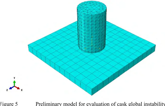
The initial analysis considers single-container casks on top of a rigid base. The initial model does not include interaction among cask inner and outer containers, or soil structure interaction (SSI) effects (Figure 5). The goal of this first model is to ensure that the FEM developed in ABAQUS can reproduce the cask-slab interaction under dynamic solicitations, and anticipate global instability. The FEM consists of 3D solid elements for all the components. The cask elements are Linear-Explicit Tetrahedral elements (C3D4), whereas the concrete pad elements are Linear-Explicit Hexahedral elements (C3D8R). The effect of nonlinear material behavior on the cask-concrete interaction is not included yet.
Figure 5 Preliminary model for evaluation of cask global instability
The material concrete for the foundation pad was modeled with a compressive strength 6000 psi, with Poisson’s ratio = 0.20, and a modulus of elasticity 4,415,200 psi (4,415.2 ksi). The nonlinear frictional contact between the cask and the concrete pad was simulated using a predetermined frictional coefficient = 0.55.
Gravity was applied in downward vertical direction as a load, to provide the mass of the model a vector. For this initial study, the only evaluated time history analysis is Northridge 1994/01/17 earthquake at Pacoima Dam station (Table 1, Figure 6). The record was selected because its large horizontal and vertical accelerations may induce sliding or tip over in the cask. During the analysis, the three orthogonal accelerations were simultaneously applied, considering the bottom of the concrete pad as a boundary condition.
Table 1 Seismic ground motion for preliminary evaluation
Rec. No.
Record/Component Earthquake Component Station PGA Mw R (km)
1
NORTHR/PUL-UP
Northridge 1994
Vertical 24207 Pacoima Dam (upper
left)
1.229
6.7 8
NORTHR/PUL 104
Horizontal-EW
1.585
NORTHR/PUL 194 Horizontal-NS 1.285
Figure 6 Acceleration time history of Northridge Earthquake. EW Horizontal Direction
-1 -0.5 0 0.5 1 1.5 2
0 5 10 15 20 25 30 35 40
A
cce
leatio
n (
g)
Figure 7 shows the horizontal displacement in “x” and “y” directions at the bottom center of the cask for the case with aspect ratio ⁄ 0.65. For this particular realization, sliding was observed, but the cask did not tip over.
Figure 7 Bottom center of cask movement in horizontal directions due to seismic excitations
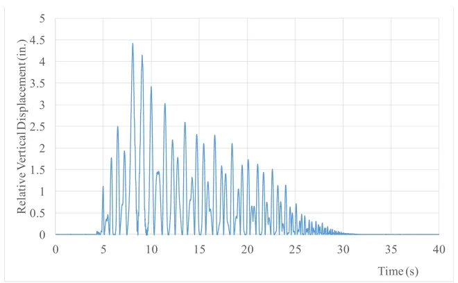
Because of the large vertical accelerations, the cask lifts and separates from the concrete pad during the strong part of the acceleration (Figure 8). This figure shows the relative vertical displacement of the bottom center cask with respect to the concrete displacement. As observed, the cask separates from the concrete pad about 2.5 in. at the center of the bottom lid. Note that the bottom center of the cask takes about 20 seconds to make contact once again with the concrete pad. Figure 9 shows the relative vertical displacement at the bottom edge of the cask. In this case, the maximum separation of the cask is close to 4.5 in, which is expected, given that the maximum separation at the bottom center is about half of this value. The node at the edge of the bottom lid makes contact with the concrete pad at each cycle (approximately every 0.6 s.). These observations and the horizontal movement of the cask, indicate that after the large initial separation at about 7-8 s., the cask vibrates and exhibits circular rocking during the rest of the time history.
These initial analyses did not show tip over events, which was expected from the static equilibrium equations, given that a cask with a relatively high aspect ratio ⁄ has the mass centroid relatively low. Casks with high ⁄ ratios correspond to relatively short ‘squat” casks that tend to be more stable. Thus, sliding is a more likely global instability outcome for this configuration. For instance, the rocking angle was monitored at the vertical axis at the center of the cask. It was found that the maximum angle is 2 degrees, indicating that the global instability effect that will take place is cask sliding.
-1 0 1 2 3 4 5 6 7 8
-8 -7 -6 -5 -4 -3 -2 -1 0 1
Displa
ce
m
en
t in NS
Dir
ec
tion (
in.
)
Figure 8 Relative vertical displacement of bottom center of cask
Figure 9 Relative vertical displacement of bottom edge of cask
CONCLUSIONS
The study presents preliminary results of a numerical and experimental evaluation on the dynamic stability of dry cask storages subjected to strong seismic events. Initial models were developed in ABAQUS/Explicit to consider that the response under dynamic excitations in three orthogonal directions results in highly non-linear friction contacts at the cask-pad interface.
The initial analysis considers a single-container cask on top of a rigid base. The results show that, because of the large vertical accelerations, the cask lifts and separates from the concrete. The maximum measured accelerations were in the order of 4-5 in. The current results indicate that the FEM developed in ABAQUS can reproduce the cask-slab interaction under dynamic solicitations, and predict global instability. The cask was subjected to a very strong seismic event to show that the system can simulate the complex non-linear interaction between the cask and the concrete pad.
0 0.5 1 1.5 2 2.5 3
0 5 10 15 20 25 30 35 40
R ela tiv e V er ti ca l Displ ac em en t ( in. ) Time (s) 0 0.5 1 1.5 2 2.5 3 3.5 4 4.5 5
0 5 10 15 20 25 30 35 40
In the next stage of the investigation, detailed FEMs will be developed to include the several internal components of the casks, such as the multi-purpose canister and fuel basket. These models will include SSI effect. Ultimately, the results of the simulation will be verified by experimental tests on a shake table with six-degrees-of-freedom.
ACKNOWLEDGMENTS
This material is based upon work supported under a Department of Energy Nuclear Energy University Programs. Any opinions, findings, conclusions or recommendations expressed in this publication are those of the authors and do not necessarily reflect the views of the Department of Energy Office of Nuclear Energy.
REFERENCES
1. 10 CFR Part72. Licensing Requirements for Independent Storage of SNF and HLW. 2. ACI 349-06 (2006) “ACI 349-06.” American Concrete Institute. Detroit, Michigan, 2006.
3. ASME (2004). “ASME Boiler and Pressure Vessel Code, Section III, Division 1.” New York City, NY: American Society of Mechanical Engineers. ASME International, 2004.
4. Benjamin JR and CA Cornell (1970) “Probability, statistics, and decision for civil engineers,” McGraw Hill, Inc. New York.
5. Bjorkman GS, DP Moore, JJ Nolin, and VJ Thompson (2001) “Influence of ISFSI Design Parameters on the Seismic Response of DSCs.” SMiRT 16, WS DC. Paper # 1601.
6. Gülerce Z, NA Abrahamson (2011) “Site-Specific Design Spectra for Vertical Ground Motion.” Earthquake Spectra, Volume 27, No. 4, pages 1023–1047, November 2011.
7. Kadak AC, K Yost (2010) “Key issues associated with interim storage of used nuclear fuel.” Center for Advanced Nuclear Energy Systems. MIT-NFC-TR-123. December 2010.
8. Ko Y-Y, S-Y Hsu, and C-H Chen (2009) “Analysis for seismic response of dry storage facility for spent fuel.” Nuclear Engineering and Design 239 (2009) 158-168.
9. Luk, VK, BW Spencer, IP Lam, RA Dameron (2005) “Parametric evaluation of seismic behavior of freestanding spent fuel DSC systems.” NUREG/CR-6865. SAN2004-5795P.
10. SECY-98-071 (1998) “Exemption to 10 CFR 72.102(f)(1) Seismic Design Requirement for Three Mile Island Unit 2 Independent Spent Fuel Storage installation.” April 8, 1998
11. Shah M, PA Cox, and A Chowdhury (2003) “Tip-Over of the HI-STORM Dry Storage Cask System. SMiRT 17, Prague, Czech Republic, August 2003. Paper # B02-2.
12. Tripathi BP, and JR Hall (2007) “Seismic slope stability and design/analysis of an ISFSI pads.” SMiRT 19, Toronto, August 2007. Paper # K07/1.
13. USNRC (2000) “Standard Review Plan for Spent Fuel Storage Facilities.” NUREG-1567.
14. USNRC (2003) “Regulatory Guide 3.73, Site Evaluations and Design Earthquake Ground Motion for Dry Cask Independent Spent Fuel Storage.” October 2003.