ISSN(Online): 2320-9801
ISSN (Print): 2320-9798
I
nternational
J
ournal of
I
nnovative
R
esearch in
C
omputer
and
C
ommunication
E
ngineering
(An ISO 3297: 2007 Certified Organization)
Vol. 4, Issue 11, November 2016
Lifetime Improvement of Wireless Sensor
Network using Network Coded Adaptive Duty
Cycle
Shobhit Tyagi1 Jitendra Singh Mathur 2
M. Tech Student, Dept. of Electronics and Communication, RGPV Bhopal, India1
Assistance Professor, Dept. of Electronics and Communication, TIT Bhopal, India2
ABSTRACT: Wireless sensor networks are designed of simple circuits, low energy consuming embedded devices with different type of physical sensors, signal processing unit and wireless communicating devices. Main objective of this design to minimizing energy consumption and maximizing network lifetime are important issues in the design of protocols for sensor networks.
Wireless sensor network consists of automatic sensors, which have a limited power battery. Nodes which are present near the centralized collecting point will be in demand of much power which limits the overall network life time. The active area near to the sink node makes a bottleneck zone because of large traffic- flow which minimize the network lifetime in wireless sensor network. In this project, we introduce an adaptive duty cycle and encoding technique for minimizing energy consumption in the bottleneck zone .An efficient communication technique has been adopted in the bottleneck zone by combining adaptive duty cycle and encoding technique. Energy efficiency of the bottleneck zone increases due to more volume of data will be transmitted to the sink with the same number of transmissions. Hence the lifetime of wireless sensor network is enhanced. This work archive to enhance the energy efficiency of the bottleneck zone which leads to overall improvement of the network lifetime by considering a network coded adaptive duty cycle WSN. Linear Network coding is not simply relaying the packets of information they receive, the sensor nodes of a network take several packets and combine them together for transmission and applied in bottleneck zone. By applying the above techniques the overall life time of the node will finally increases. This proposed system investigates life time improvement approximately 8% - 14%, and minimizing energy consumption.
KEYWORD: WSN, Duty Cycle, Network Coding, Network Lifetime, Upper Bound
I. INTRODUCTION
The sensor nodes with multiple functions that are compact size and communicate in a limit in short distances are developed due to the recent advancement in electronic fabrication on Nano level and wireless communication technologies. Wireless sensor networks [1] consisted of different functioned of small sensor motes. These compact sensors have the capability of signal processing, sensing and transmitting and receiving signals with each other and to the outside world using the external center stations.
These sensor motes are largely used in remote location, medical, commercial, industrial, and army security applications [2]. Wireless sensor network devices have limited battery energy to complete processing and communication task.So, one of the challenging issues in wireless sensor networks is designing alow energy consuming network.
ISSN(Online): 2320-9801
ISSN (Print): 2320-9798
I
nternational
J
ournal of
I
nnovative
R
esearch in
C
omputer
and
C
ommunication
E
ngineering
(An ISO 3297: 2007 Certified Organization)
Vol. 4, Issue 11, November 2016
established that the sole approach a node will save substantial energy is to power off the radio, since sending, receiving associated taking note of an idle channel square measure functions that need roughly identical quantity of power. One in all the fundamental and most typically used power management techniques is Duty sport. Duty sport may be a technique wherever a node is sporadically placed into the sleep mode that is a good technique of reducing energy dissipation in wireless device networks. The traffic load in typical wireless device networks is comparatively low (0.01 to ten packets/second) and packets area unit comparatively short (less than five hundred bits). The nodes pay most of their time idle for watching the channels. By introducing significant duty athletics in every node the advantage of low activity rate may be taken. In duty cycled operation [6], a node follows a sleep-wake and communicate cycle during which majority of the cycle pay their time in low power sleep state. Because duty cycle will increase, the nodes will sleep longer and additional energy are going to be saved, whereas few of the nodes area unit accessible to participate in information routing, which is able to decrease the turnout and increase transmission latency to cut back the duty cycle, we should always decrease the active time of the node the maximum amount as doable taking into consideration some limitations. Duty-cycled doesn't need continuous sampling or communication that makes its operation doable in wireless sensor network.
A duty cycled wireless sensor network is of two types. First is random duty cycle in which duty cycle is not definite can be change randomly [10], second is co-ordinated duty cycle in which protocol is used to synchronize sensor so that they can communicate to each other[11]. A third technique is proposed in this paper which is known as queue management based adaptive technique. In random duty –cycle the sensing element motes are turned on or off stage in random fashion. Disadvantage of random duty cycled wireless sensor network never visit the sleep state supported their network condition. It will be generating the significant traffic. It does not use higher utilization of information accessed. In co-ordinated duty cycle wireless sensor network the sensing element transmits and receives the signal among themselves through the communication and message exchange. However, it needs further information exchange to broadcast the active sleep schedules of every node. These ways of wireless sensor network generate the significant traffic and overhead. We tend to propose an adaptive duty cycle management mechanism supported the queue management with the aims of power saving and time delay reduction. The projected theme does not like specific state information from the neighbour nodes, however solely uses the possessive queue length obtainable at the node. The network condition or traffic variations changes implicitly happens as a result of the queue states having risk or power of the network states. Victimization the queue length and its variations of a sensing element node, we tend to gift a style of distributed duty cycle network controller. Thus the adaptive duty-cycled primarily based wireless sensor network has been thought of for its style. Specifically the matter of reduction of traffic in bottleneck zone has been thought of.
II. RELATED WORK
Energy may be a terribly thin resource for sensing element systems and should be managed reasonably so as to increase the lifetime of the sensing element nodes. Several works are done to scale back the ability consumption and lifelong of wireless sensing element networks. Normally two main facultative techniques are known i.e. duty athletics and data- driven approaches. Duty athletics [6] is that the simplest energy-conserving operation within which whenever the communication isn't needed, the radio transceiver is placed within the sleep mode.
ISSN(Online): 2320-9801
ISSN (Print): 2320-9798
I
nternational
J
ournal of
I
nnovative
R
esearch in
C
omputer
and
C
ommunication
E
ngineering
(An ISO 3297: 2007 Certified Organization)
Vol. 4, Issue 11, November 2016
paper, the Packet Delivery magnitude relation (PDR) values are achieved by three strategies. in step with their simulation, all told the three strategies the PDR results are terribly shut and better than ninety seven for lightweight traffic hundreds. With a rise in traffic load, the constant duty cycle methodology performs the simplest as a result of its higher duty cycle will give a lot of awake nodes to participate in knowledge routing. The marginally worse performance of TDDCA (Traffic- adaptive Distance-based Duty Cycle Assignment) compared to the constant duty cycle methodology indicates that the fastened increments and decrements in duty cycle isn't economical in terms of PDR. TDDCA and DDCA (Distance-based Duty Cycle Assignment) are a lot of energy-efficient than the constant duty cycle methodology, which DDCA performs higher than TDDCA.
III.ENERGYCALCULATIONANDMODELLING
The lifetime of the nodes is evaluated by the overall energy consumption of the nodes such as in [12]. If the energy consumption decreases, then the life time of the nodes is increased. The total energy consumed by the nodes consists of the energy consumed for receiving transmitting andsleeping . The notations and values listed in Table 1 and Table 2 are used throughout the paper. Total energy consumed is given by
= + +
A device node consumes energy at completely different states, such as, sensing and generating knowledge, sending, receiving and sleeping state. During this work, the radio model [14] has been changed for a requirement cycle primarily based WSN. Energy savings area unit done at the node level through shift between active and sleep states.
Energy consumption by a supply node per second across a distance l with path loss exponent η is, = ( + )eq. (1)
Where is the data rate of transceiver relay, is the energy consumption per bit by the transmitter and is the energy consumption per bit in the transmit op-amp [14]. Total energy consumption in time t by a leaf mote without acting as a relay (intermediate node) is,
= [ ( + ) + (1− ) ]eq. (2)
where is the idle mode energy consumption of a sensor node per second, is the sensor’s average sensing rate and it is equal for all the nodes, is the energy consumption of a mote to sense a bit, the probability p is the average proportion of time t that the sensor node use in active mode. Thus, p is the duty-cycle. A sensor node remains in the idle state with probability (1-p) till time t. The energy consumption per second by an intermediate node which act as a relay mote is given by
= + + eq. (3)
where is the energy consumption by the sensor node to receive a bit. Total energy consumed till time t by an intermediate (relay) node is
= [ ( + ) + (1− ) ]eq. (4)
The total energy consumption in the bottleneck zone in time t for a p duty-cycle wireless sensor network is given by = + + + (1− ) eq.(5)
= + + ∫ ∫ − + (1− ) eq.
(6)
Where d is node density, is area of bottleneck zone and is area of sensor network.
When p=1 and m=1 the energy consumption in the bottleneck zone to relay the data bits that are generated inside as well as outside the bottleneck zone becomes same as in a general or same as wireless sensor network without any duty cycle [13]. Thus, (6) also covers the general network scenario without considering duty cycle of nodes.
The lifetime of a wireless sensor network is significantly depended on the energy consumption at the node level. Let is the initial battery energy available at each sensor node. In a network of N nodes, the energy reserve at the start is .
ISSN(Online): 2320-9801
ISSN (Print): 2320-9798
I
nternational
J
ournal of
I
nnovative
R
esearch in
C
omputer
and
C
ommunication
E
ngineering
(An ISO 3297: 2007 Certified Organization)
Vol. 4, Issue 11, November 2016
≤ .
Thus ≤ eq.(7)
where the term Pxis given by
= ( − ) +∫ ∫ + − + (1− ) eq. (8)
The amount of energy consumption is maximum when p=1 (i.e. all node active condition) and the lifetime minimizes in a wireless sensor network. The energy efficiency of the network increases with low duty cycle which enhances the lifetime of the network.
IV.ADAPTIVEDUTYCYCLE
A system is taken into account with N number of motes distributed uniformly in space . Seventy percent of motes are adaptive duty cycle enabled that means switching between active and sleep state supported their queue length) within the area , the nodes are divided into two teams reminiscent of relay device and network coder motes. The active relay device nodes(R) transmit the information that is generated outside similarly as within the bottleneck area. Within the bottleneck zone the relay nodes will communicate to the sink employing a single hop communication, the relay node communicate to the another relay node and Liner network coded mote employing a multi hop communication. The active Linear Network coder motes write in code the relay node information before transmission to the sink. It uses the one hop to speak with the sink. The leaf device nodes sporadically sense the info and transmit them to the neighbouring nodes towards the sink. The intermediate device nodes sporadically sense the information and it'll relay the detected information and received data within the direction of sink S.Each device node encompasses a variety of Received queue and detected Queue hooked up thereto, one or a lot of to alternative nodes, a lot of to the sink. On every device node the packets are arrived and depart except the Leaf (or) Terminal node and Sink node. The planned approach is to dedicate the buffer at every node to one inventory accounting queue. Once the buffer occupancy exceeds a threshold the switch begins to the device node as a vigorous state to try to thus till buffer occupancy falls below the brink.
Fig. 1: Flow chart of project Start
Defining roles of motes
Is queue greater than threshold
mote to sleep mode Encode using if encoder
mote and send
Received data encoded and processed
ISSN(Online): 2320-9801
ISSN (Print): 2320-9798
I
nternational
J
ournal of
I
nnovative
R
esearch in
C
omputer
and
C
ommunication
E
ngineering
(An ISO 3297: 2007 Certified Organization)
Vol. 4, Issue 11, November 2016
V. MATLABSIMULATION&RESULTSANALYSIS 1.Network Lifetime using Random Duty Cycle
In this project area of wireless sensor network is considered 200x200 square meter, diameter of bottleneck zone 60m, number of nodes 1000, battery energy 25kj, sleep energy 30uj,hop length 2, number of bits 960 and threshold 12 bit are considered.
Fig. 2 shows wireless sensor network lifetime variation with respect to change in random duty cycle. When duty cycle value is 0.01, lifetime for m=1 is 8.26x10^8 seconds. With increase in value of duty cycle, lifetime decreases and with increase in value of traffic density, lifetime again decreases. For maximum value of traffic density m=9, lifetime 4x10^8 is observed.
2. Network Lifetime using Network Coded Random Duty Cycle
Fig. 3 shows wireless sensor network lifetime variation with respect to change in r duty cycle. Here in this graph network coding is applied with duty cycle. When duty cycle value is 0.01, lifetime for m=1 is 8.32x10^8 seconds. As value of duty cycle increases lifetime decreases, and with the increase in value of m (traffic density) lifetime decreases.
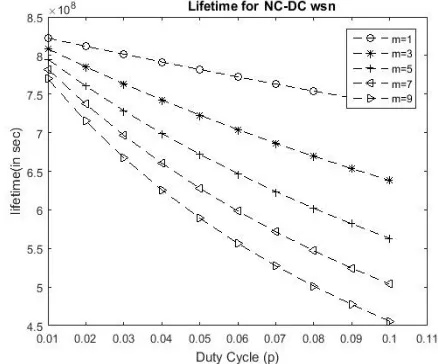
3. Network Lifetime using Network Coded Adaptive Duty Cycle
Fig 4 shows wireless sensor network lifetime variation with respect to change in random duty cycle. When duty cycle value is 0.01, lifetime for m=1 is 8.38x10^8 seconds. As value of duty cycle increases lifetime decreases, and with the increase in value of m (traffic density) lifetime decreases. For m=9 and p=0.01 lifetime is 7.8x10^8 seconds.
Table 1: Parameters
Number of Nodes (N) 1000
Network Area 200 m2
Path Loss Exponent 2
0.937uj 0.787uj 0.0172uj
Sleep 30uj
Fig. 2: Lifetime of Sensor Network using Random Duty Cycle Fig. 3: Lifetime of Sensor Network using Network Coded Duty cycle
ISSN(Online): 2320-9801
ISSN (Print): 2320-9798
I
nternational
J
ournal of
I
nnovative
R
esearch in
C
omputer
and
C
ommunication
E
ngineering
(An ISO 3297: 2007 Certified Organization)
Vol. 4, Issue 11, November 2016
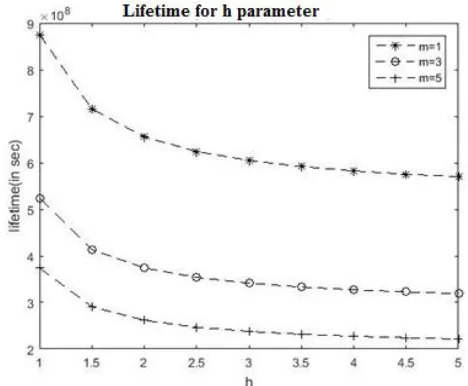
Fig. 4: Lifetime of Sensor Network using Adaptive Duty Cycle Fig.5: Lifetime of Sensor Network at different values of m for h parameters and Network Coding
Table 2 shows the comparison of lifetime for random duty cycle, network coded duty cycle and network coded adaptive duty cycled wireless sensor network. From the data it can be conclude that the network coded adaptive duty cycled wireless sensor network is best technique to improve network lifetime.
Table 2: Lifetime comparison for different techniques
Lifetime for p=0.01 Lifetime for p=0.1 Random Duty Cycle 5.06 x10^8 2.38 x10^8 Network Coded Duty
Cycle
5.19 x10^8 2.89 x10^8
Adaptive Duty Cycle with Network Coding
7.69 x10^8 5.32 x10^8
Fig.5 shows, how network lifetime is depends on h parameter. It can be observe that with increment in value of h value of lifetime degrades. For higher values of h parameter, lifetime value is almost constant.
VI.CONCLUSION
ISSN(Online): 2320-9801
ISSN (Print): 2320-9798
I
nternational
J
ournal of
I
nnovative
R
esearch in
C
omputer
and
C
ommunication
E
ngineering
(An ISO 3297: 2007 Certified Organization)
Vol. 4, Issue 11, November 2016
REFERENCES
[1]JAMAL N.AL-KARAKI AND AHMED E.KAMAL,“ROUTING TECHNIQUES IN WIRELESS SENSOR NETWORKS:SURVEY”, WIRELESS COMMUNICATIONS, IEEE,VOLUME:11, ISSUE:6,DEC.2004
[2] Y. A. Malkani, A. Keerio, J. A. Mahar, G. A. Memon and H. Keeriom, (2012) “Routing and Data Gathering in Wireless Sensor Networks (WSNs), Vol. 44, pp. 15-22,2012.
[3] Tokuya Inagaki and Susumu Ishihara, “HGAF: A power saving scheme for wireless sensornetwork”, Journal of Information Processing,vol. 17 pp. 255-266,2009
[4] FotisKerasiotis, AggelikiPrayati, Christos Antonopoulos, George Papadopoulos, (Lifetime Prediction Model for a WSN Platform”,2010 Fourth
International Conference on 18-25 July 2010
[5] Chulsung Park, KanishkaLahiri and AnandRaghunathan, (2005) “Battery Discharge Characteristicsof Wireless Sensor Nodes”, An Experimental
Analysis”,Conference PaperOctober 2005
[6] E. Y. A. Lin, J. M. Rabaey, and A. Wolisz, “Powerwireless sensor networks,” Proceedings of the IEEE International Conference on Communicationspp. 3769–3776, June 2004.
[7] Honghai Zhang and Jennifer C. Hou, Maximizing1(1/2), pp. 64-71,2006.
[8] MS Pawar, JA Manore, MM Kuber, ‘Life Time Prediction of Battery Operated Node for EnergyEfficient WSN Applications’, IJCST Vol. 2, Issue 4, Oct .2011
[9] Yuqun Zhang, Chen-Hsiang Feng, IlkerDemirkol, WendiRabinerHeinzelman: Energy-Efficient Duty Cycle Assignment for Receiver-Based Convergecast in Wireless Sensor Networks, pp: 1-5,2003.
[10] HeejungByun, Junglok Yu, "Adaptive Duty Cycle Control with Queue Management in Wireless Sensor Networks," IEEE Transactions on Mobile Computing, vol. 12, no. 6, pp. 1214-1224, , doi:10.1109/TMC.2012.102, June 2013.
[11] RashmiRanjan Rout, Soumya K Ghosh, “Enhancement of Lifetime using Duty Cycle and Network Coding in Wireless Sensor Networks,” IEEE Transactions on Wireless Communications, 12(2), 656-667, February 2013.
[12] H. Zhang and J. C. Hou, “On the upper bound of α−lifetime for large sensor networks,” ACM Trans. Sen. Netw., vol. 1, no. 2, pp. 272–300,
2005.
[13] Ahmed M. Khedr, WalidOsamy, ”Mobility-assisted minimum connected cover in a wireless sensor network,” J. Parallel Distrib. Comput. 72(7): 827-837 (2012).
[14] M. Bhardwaj, T. Garnett, and A. Chandrakasan, “Upper bounds on the lifetime of sensor networks,” in IEEE ICC, pp. 785–790,2001
BIOGRAPHY
Shobhit Tyagi Obtained his Bachelor’s degree in Electronics and Communication from UPTU and Master’s degree in Electronics and Communication from Technocrats Institute of Technology(Excellence), University of R.G.P.V. Bhopal,Madhya Pradesh (MP).