Scholarship@Western
Scholarship@Western
Electronic Thesis and Dissertation Repository
1-25-2012 12:00 AM
Development of a Three-Dimensional Image-Guided Needle
Development of a Three-Dimensional Image-Guided Needle
Positioning System for Small Animal Interventions
Positioning System for Small Animal Interventions
Christopher S.R. Waring
The University of Western Ontario
Supervisor James Lacefield
The University of Western Ontario Joint Supervisor Aaron Fenster
The University of Western Ontario
Graduate Program in Biomedical Engineering
A thesis submitted in partial fulfillment of the requirements for the degree in Master of Engineering Science
© Christopher S.R. Waring 2012
Follow this and additional works at: https://ir.lib.uwo.ca/etd
Part of the Biomedical Engineering and Bioengineering Commons
Recommended Citation Recommended Citation
Waring, Christopher S.R., "Development of a Three-Dimensional Image-Guided Needle Positioning System for Small Animal Interventions" (2012). Electronic Thesis and Dissertation Repository. 375.
https://ir.lib.uwo.ca/etd/375
This Dissertation/Thesis is brought to you for free and open access by Scholarship@Western. It has been accepted for inclusion in Electronic Thesis and Dissertation Repository by an authorized administrator of
(Spine title: Image-guided needle positioning system for small animal interventions) (Thesis format: Integrated Article)
by
Christopher Stanley Robert Waring
Graduate Program in Biomedical Engineering
A thesis submitted in partial fulfillment of the requirements for the degree of
Master of Engineering Science
The School of Graduate and Postdoctoral Studies The University of Western Ontario
London, Ontario, Canada
ii
THE UNIVERSITY OF WESTERN ONTARIO School of Graduate and Postdoctoral Studies
CERTIFICATE OF EXAMINATION
Supervisor
______________________________ Dr. Aaron Fenster
______________________________ Dr. James C. Lacefield
Supervisory Committee
______________________________ Dr. David W. Holdsworth
______________________________ Dr. Shaun Salisbury
Examiners
______________________________ Dr. Maria Drangova
______________________________ Dr. James Johnson
______________________________ Dr. Keith St. Lawrence
The thesis by
Christopher Stanley Robert Waring
entitled:
Development of a three-dimensional image-guided needle
positioning system for small animal interventions
is accepted in partial fulfillment of the requirements for the degree of Master of Engineering Science
iii
Abstract
Conventional needle positioning techniques for small animal microinjections are
fraught with issues of repeatability and targeting accuracy. To improve the outcomes of
these interventions a small animal needle positioning system guided by micro-computed
tomography (micro-CT) imaging was developed. A phantom was developed to calibrate the
geometric accuracy of micro-CT scanners to a traceable standard of measurement. Use of the
phantom ensures the geometric fidelity of micro-CT images for use in image-guided
interventions or other demanding quantitative applications. The design of a robot is
described which features a remote center of motion architecture and is compact enough to
operate within a micro-CT bore. Methods to calibrate the robot and register it to a micro-CT
scanner are introduced. The performance of the robot is characterized and a mean targeting
accuracy of 149 ± 41 µm estimated. The robot is finally demonstrated by completing an in
vivo biomedical application.
Keywords
medical robotics, image-guided interventions, small animal imaging, x-ray micro-computed
iv
Co-Authorship Statement
Chapter 2
Chapter 2 is in preparation to be submitted to Medical Physics with the author list:
Christopher Waring, Jeffrey S. Bax, Amila Samarabandu, David W. Holdsworth, Aaron
Fenster and James C. Lacefield. Jeff designed and constructed the calibration phantom. Jeff
also developed the method to measure the calibration phantom to a traceable standard. The
construction and measurement of the phantom was completed by Jeff with assistance from
the laboratory machinists Jacques Montreuil and Kevin Barker. I was responsible for
developing the algorithm and software for processing the micro-CT images of the phantom to
characterize the scanner geometric accuracy. Amila was a summer research assistant who
assisted in the development of the software. I was responsible for collecting images of the
phantom and performing all image analysis. The work presented in this chapter was
performed under the supervision of David W. Holdsworth, James C. Lacefield and Aaron
Fenster.
Chapter 3
Chapter 3 is in preparation to be submitted to Medical Physics with author list:
Jeffrey S. Bax, Christopher Waring, Shi Sherebrin, Shawn Stapleton, James C. Lacefield and
Aaron Fenster. For this study, Jeff designed and calibrated the prototype robotic device that
was constructed by our laboratory machinists: Jacques Montreuil and Kevin Barker. Shi and
Jeff developed the kinematic control software for the robot. Shi was responsible for the
design and construction of the electric hardware with the assistance of our electrician, Janos
Bartha. Jeff and I together developed the needle calibration and robot registration methods. I
was responsible for developing the methods and software to characterize the systems
performance and carrying out the image analysis. I was also responsible for developing the
robot registration software. Shawn acquired all of the CT images and in addition, designed
and performed the animal experiments. Work on this project was performed under the
v
vi
Acknowledgments
I would like to acknowledge the many people who contributed to my course of
studies while at Robarts:
I would first like to thank supervisors James Lacefield and Aaron Fenster for their
guidance and insight throughout my project. I would also like to thank the other members of
my advisory committee: David Holdsworth and Shaun Salisbury. Special thanks to David
Holdsworth for his guidance in the micro-CT calibration portion of my thesis.
Thanks also go to all of the members of the Lacefield and Fenster labs during my
time at Robarts. Special thanks go to Jeff Bax who I closely collaborated with throughout
the course of my research. This project would not have been possible without his knowledge
and skill in mechanical design. I would also like to thank the Fenster lab machinists Jacques
Montreuil and Kevin Barker who fabricated much of what is presented in this thesis. Thanks
also go to Shi Sherebrin and Janos Bartha for development and construction of the robot
electronic hardware. I would also like to thank Joseph Umoh, the micro-CT imaging facility
manager, for patiently spending many hours helping to acquire images.
I would like to thank David Jaffray and his lab at the University Health Network for
their assistance and for the use of their micro-CT scanner. I want to thank Shawn Stapleton
and Mike Dunne from the Jaffrey lab for spending many long days behind the micro-CT
console with Jeff and I. In addition, I would like to thank Shawn for his help in developing
and performing the small animal experiments.
Finally, I would like to acknowledge my personal funding sources during the course
of my degree: a scholarship from the Natural Sciences and Engineering Research Council
training program in Computer Aided Medical Interventions from 2009-2011 and a Western
vii
Table of Contents
CERTIFICATE OF EXAMINATION ... ii
Abstract ... iii
Co-Authorship Statement... iv
Table of Contents ... vii
List of Tables ... xi
List of Figures ... xii
Chapter 1 ... 1
1 Introduction ... 1
1.1 Medical Robotics ... 1
1.1.1 Clinical Role of Medical Robotics ... 1
1.1.2 Medical Robot Architecture ... 3
1.2 Small Animal Needle Interventions ... 5
1.3 Preclinical Robotic Needle Positioning Systems ... 6
1.3.1 Current Preclinical Needle Positioning Systems ... 6
1.4 Preclinical Robot Workflow ... 8
1.4.1 Needle Calibration ... 8
1.4.2 Robot to Imaging Modality Registration ... 10
1.4.3 Needle Placement... 13
1.5 Drawbacks of Current Preclinical Systems... 14
1.6 X-Ray Computed Tomography... 16
1.7 Technical Objectives ... 18
1.8 Outline of Thesis ... 19
viii
1.8.2 Chapter 3: 3D Image-Guided Robotic Needle Positioning System for
Small Animal Interventions ... 19
References ... 21
Chapter 2 ... 29
2 Traceable Micro-CT Geometric Accuracy Phantom for Applications Requiring Exact Measurement of Distances or Volumes ... 29
2.1 Introduction ... 29
2.2 Methods... 31
2.2.1 Calibration Phantom Construction ... 31
2.2.2 Measurement of Bead Positions within Calibration Phantom ... 32
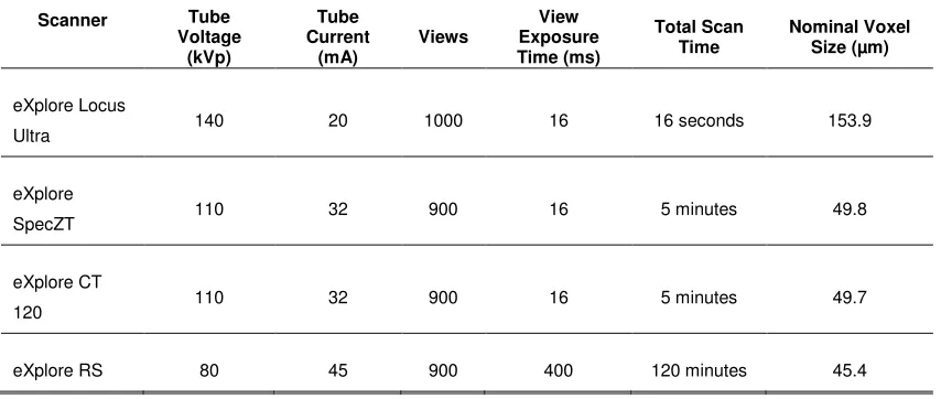
2.2.3 Imaging the Calibration Phantom ... 34
2.2.4 Geometric Correction Calculation ... 35
2.2.5 Validation Phantom Construction ... 36
2.2.6 Data Analysis ... 37
2.3 Results ... 38
2.3.1 Correction Factor Values ... 38
2.3.2 Geometric Correction to Calibration Phantom ... 40
2.3.3 Geometric Correction to Validation Phantom ... 41
2.3.4 Comparison of Validation Phantom Errors... 42
2.4 Discussion ... 42
2.5 Conclusion ... 45
References ... 46
Chapter 3 ... 48
3 3D Image-Guided Robotic Needle Positioning System for Small Animal Interventions ... 48
3.1 Introduction ... 48
ix
3.2.1 Mechatronic System Design ... 50
3.2.2 Robot Calibration ... 56
3.2.3 Robot to micro-CT Registration ... 61
3.2.4 Robot Targeting Accuracy ... 64
3.2.5 Preclinical Application... 66
3.3 Results ... 67
3.3.1 Robot Calibration ... 67
3.3.2 Robot Positioning Accuracy ... 70
3.3.3 Preclinical Application... 71
3.4 Discussion ... 74
3.4.1 Robot Calibration ... 74
3.4.2 Robot Registration ... 76
3.4.3 Robot Positioning Accuracy ... 77
3.4.4 Preclinical Application... 80
3.5 Conclusion ... 80
References ... 82
Chapter 4 ... 85
4 Summary and Future Work ... 85
4.1 Summary ... 85
4.1.1 Chapter 2: Traceable Micro-CT Geometric Accuracy Phantom for Applications Requiring Exact Measurement of Distances or Volumes .... 85
4.1.2 Chapter 3: 3D Image-Guided Robotic Needle Positioning System for Small Animal Interventions ... 86
4.2 Conclusion ... 88
4.3 Future Work ... 89
4.3.1 Improved Software Integration and Intervention Planning ... 89
x
4.4 Final Remarks ... 91
References ... 92
xi
List of Tables
Table 1.1-Summary of existing image-guided small animal needle positioning systems ... 7
Table 2.1-Summary of the micro-CT scan parameters used for imaging the phantoms ... 34
Table 2.2-Calculated average scanner correction factors for each axis. ... 38
Table 2.3-Results of Tukey test for differences in the mean correction factors for each pair of scanner axes ... 39
Table 2.4-Uncorrected and corrected bead separation errors for the calibration phantom ... 40
Table 2.5-Uncorrected and corrected bead separation errors for the validation phantom ... 41
Table 3.1-Summary of the results obtained for each experiment with robotic system... 68
xii
List of Figures
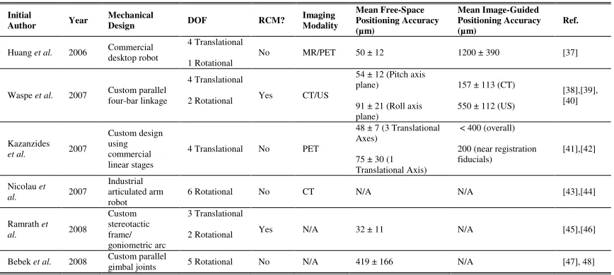
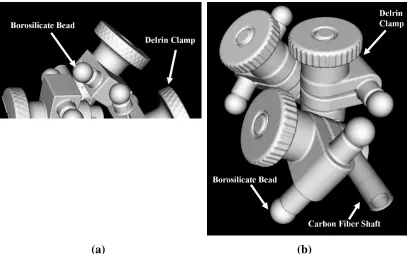
Figure 2.1-Micro-CT surface rendering of the a) calibration phantom and b) validation
phantom... 32
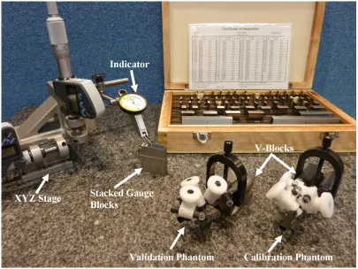
Figure 2.2- Calibration and validation phantom with measurement equipment ... 33
Figure 3.1- A schematic representation of the proposed RCM linkage design ... 52
Figure 3.2- (Top): Photograph of the robotic apparatus mounted on the CT scanner animal
couch and control system. (Bottom): Photograph of the forward spherical linkage and
attached needle driver ... 54
Figure 3.3- Photograph of the calibration fixture used to set the needle tip position at the
RCM when the needle driver is in its forward position ... 60
Figure 3.4- View of reconstructed CT image used for the needle targeting experiment ... 65
Figure 3.5- Composite photographs of the calibration photos showing the pitch (Top Left)
and roll (Top Right) of the needle throughout its full range of motion. The bottom two
photographs shows a close-up view of the segmented needle tip locations in the pitch
(Bottom Left) and roll (Bottom Right) directions... 69
Figure 3.6- Photograph of the experimental setup used for the animal interventions (a)
outside, and (b) inside of the bore of the CT scanner ... 72
Figure 3.7- Wick-in-needle measurements of IFP using robot positioning ... 73
Figure 3.8- Projection views obtained from two sequential CT scans which demonstrate the
ability to perform image-guided needle placement in vivo ... 74
Figure 3.9- A composite image of the needle tracks from the needle angulation accuracy
Chapter 1
1
Introduction
1.1 Medical Robotics
1.1.1 Clinical Role of Medical Robotics
The first demonstration of using a robot to complete a medical intervention was in
1985 at the Memorial Medical Center of Long Beach [1]. An off-the-shelf Puma 200
industrial robot was used to complete the biopsy of a suspicious brain lesion. The robotic
procedure was an attempt to complete an existing procedure faster with higher reliability
and accuracy. Conventionally, the biopsy procedure had been completed using a
stereotactic frame based on technology first introduced in 1908 [2]. The stereotactic
frame had been integrated with an x-ray computed tomography (CT) scanner. To
complete the stereotactic frame procedure, the patient was first scanned using the CT
scanner and the position of the lesion localized in the image. A computer then calculated
four angular settings of the stereotactic frame and the depth required to position a needle
tip at the lesion based upon the position of the lesion in the image. The stereotactic frame
was then manually adjusted to match the calculated settings. Unfortunately, the process
required to manually adjust the stereotactic frame was found to be tedious, subject to
operator error and lack flexibility. To address these limitations, the Puma 200 robot was
placed on the scanner bed. The robot was able to quickly and automatically position a
needle bushing to correspond with the brain lesion based on a CT image. A surgeon then
used the bushing to insert the needle into the lesion and successfully complete a biopsy.
Although promising, this initial line of research was halted by the manufacturer of the
Puma 200 on the basis that an industrial robot was unsafe for surgical applications [3].
The field of medical robotics has undergone tremendous growth since its
beginnings. The number of yearly publications on the topic has experienced exponential
growth since the early 1990s. In 2005 alone, new publications on medical robotics
numbered over 600 [4]. This growth is demonstrated in the da Vinci robotic system
system developed. According to its manufacturer, an installed base of over 1700 systems
completed 278,000 procedures worldwide in 2010. This represented a growth of over
220% compared to the procedures completed in 2008 [5]. Furthermore, use of the da
Vinci system is increasingly becoming the standard of care for completing procedures
such as radical prostatectomies [6]. Along with the da Vinci, dozens of other unique
robotic systems exist to complete a wide-range of medical procedures [7]. The breadth
and ubiquity of medical robotics makes a concise study of the topic challenging.
A study of the nomenclature of medical robotics is one method for developing an
understanding of the current-state of the field. Unfortunately, the nomenclature of
medical robotics lacks convention. Authors may classify systems with a wide range of
options such as mechanical design, level of autonomy or intended application [7].
Depending upon the classification system, the resulting nomenclature may become quite
complicated and fractured. A useful high-level system for classifying medical robots
was introduced by Camarillo et al. which categorizes robots based on their role in the
medical procedure [8]. This nomenclature divides devices into three role categories:
passive, restricted and active. The passive role consists of systems that have a limited role
in the procedure or are involved in lower risk procedures. Restricted role systems are
involved in higher risk procedures, but are restricted to a specific task of the procedure.
Active role systems are a critical component of the procedure and are responsible for
high-risk tasks. Furthermore, the authors note that each of these role categories
represents an inverse trend of procedure risk to robot autonomy. Passive role systems
with the lowest risk generally have the highest degree of autonomy, while active role
systems with the highest risk generally have the lowest autonomy and remain under
direct supervision by a surgeon. This relationship arises from the same safety concerns
that in 1985 led to the end of research with the Puma 200 for brain lesion biopsy.
Robotic systems that have drifted away from this trade-off between robot autonomy and
procedure risk have seen little success [3,9].
Commercially available examples are provided by Camarillo et al. to illustrate
this method of robot categorization. Throughout these examples, the trend of increasing
Sunnyvale, CA) is a robotic system developed to complete radiosurgery [10]. Mounted
onto the CyberKnife is an x-ray linear accelerator for radiotherapy of cancer. The
CyberKnife automatically sets up and registers a radiation treatment plan developed by a
radiotherapist to the position of a patient using intra-operative images. The CyberKnife
then autonomously positions the x-ray linear accelerator to complete the plans. During
the procedure the CyberKnife never physically contacts the patient and the interaction is
considered to be lower risk. As a result, the system is categorized as a passive role
system. The next example in the restricted role is the RoboDoc (Curexo Technology
Corporation, Fremont, CA) system [11]. The RoboDoc is used for orthopedic
applications which require bone-milling, typically, total hip replacement [12]. Since
RoboDoc is in direct contact with the patient, the procedure is higher risk. RoboDoc
autonomously mills the bone based on a path developed by the surgeon using
pre-operative CT images. However, RoboDoc is not responsible for the entire orthopedic
procedure. Rather, RoboDoc is only used for a very specific portion of procedure and
only carries out the single specific task of milling. Unlike the CyberKnife, the initial
setup and plan registration to the patient is completed manually by the surgeon, limiting
RoboDoc’s autonomy. The higher risk and limited scope of the RoboDoc leads to its
restricted categorization. The previously discussed da Vinci robot serves as the final
example [13]. The da Vinci is a telerobot which operates using a slave-master system. A
surgeon sits at the master console of the da Vinci system, which contains controls and a
stereoscopic display. The surgeon uses the console to control the robotic arms of the
slave system in real time during procedures. As a result, the da Vinci systems possess
very little autonomy. The da Vinci is typically used to carry out entire minimally
invasive procedures during which it is in constant physical contact with the patient, thus
creating a high risk. The critical role of the da Vinci in completing high risk procedures
places it in the active role category. These examples serve to demonstrate the range of
roles medical robotics can fulfill with varying levels of autonomy and risk.
1.1.2 Medical Robot Architecture
A large range of potential architectures exist for robotic systems. Of these
successful in medical robotics [7,14]. The RCM was first introduced to medical robotics
in 1995 by Taylor et al. [15]. In an RCM design, the translational motion of a tool
mounted onto the robot is decoupled from the rotational motion at a fixed point in space.
In other words, both translational and rotational motion can be performed independently
of one another. The RCM allows a tool to pivot about the fixed point in space, which is
an extremely useful capability for medical applications. For example, the first
RCM-based robot developed by Taylor et al. was developed to position tools, such as a camera,
during laparoscopic surgery. In laparoscopic surgery, tools most pass through small
cannulas to enter the abdomen. The translational motion of tools passing through these
entry points must be constrained to avoid injury to the patient. The use of an RCM
provides a perfect solution to this required constraint. The RCM can be positioned to
correspond with the cannula, creating a fulcrum at the point of entry. The tool can then
be freely inserted or retracted and rotated while inserted into the patient without danger of
translation and injury. The RCM represents a very practical and useful robot architecture
for medical applications.
An RCM point is created at the common intersection point of all the rotational
axes of a robot. If all the rotational axes of a robot do not intersect, an RCM will not be
formed. The RCM can be created through either active or passive means. The RCM can
be created actively through programming of the robot to coordinate motion of all the
joints to intersect their rotational axes at a common point [16]. However, the RCM is
typically achieved passively through mechanical design and the resulting kinematics,
which constrain the rotational axes to intersect at a point. A number of different
mechanical designs can be used to achieve a passive RCM. A review of RCM robot
designs finds the parallel-bar linkage to be the most popular mechanical design [7].Other
mechanical designs that have been used to create RCMs include the goniometric arc [17]
and spherical linkage [18]. The mechanical design selected may vary depending on the
application and user preference. A schematic drawing of a spherical linkage based RCM
1.2 Small Animal Needle Interventions
Small animal models in preclinical research are critically important to expanding
medical knowledge and to the development new of treatments and therapies for human
disease [19]. From a regulatory standpoint, animal models are a typical requirement to
demonstrate the efficacy of new treatments and therapies before clinical trials [20].
Needle interventions are a common procedure performed during the course of preclinical
research. These needle interventions may be performed to inject a variety of compounds
such as imaging contrast agents [21], cancer or stem cells [22,23], and other biological or
therapeutic agents [24,25]. Interventions may also be required to position needle-like
measurement probes within small animals for data collection [26]. Conventionally,
non-robotic, manual techniques are used to complete these interventions. Typical manual
interventions used to complete these interventions include: surgical exposure of the
target, percutaneous injections through the skin or the use of a stereotactic device. Each
of these conventional techniques possesses drawbacks that could be improved upon with
the use of robotics.
Surgical exposure of targets during needle interventions allows for direct visual
localization of targets. Examples of targets for surgical exposure include the pancreas
[27], intestine [28], thymus [29] and heart [23]. Surgical exposure is typically reserved
for interventions requiring high positioning accuracy due to the ability to visually
localized targets during surgery. To improve target localization, microscopy may be used
during needle positioning [28]. Unfortunately, surgical exposure has a number of
drawbacks. Completion of the surgery is time consuming and requires highly trained
personnel. The procedure is also subject to human error and operator variability.
Surgery is highly invasive and may result in morbidity or mortality of the animal. Even
if successful, surgery may still impose pain and distress on the animal causing potential
immune dysfunction, behavioral changes and other negative physiological changes [30].
These changes may confound research results and make it difficult to discern the effects
of the experimental procedure from the surgical side-effects.
Percutaneous injections involve the positioning of a needle through the skin
carry out and are less invasive than surgical exposure. As a result, the use of
percutaneous injections is seen as a preferred alternative to surgical exposure when
completing interventions. The visual target localization provided by surgery has been
replaced with both anatomical landmarks [29]and ultrasound imaging [23,31] to localize
targets during percutaneous injections. Although percutaneous injections reduce the side
effects of procedures, they are still subject to the same issues of operator error and
repeatability. For example, injections into the tail vein are perhaps one of the most
common percutaneous injection procedures completed. However, no standard methods
exist to quantify operator competence or the success of a tail vein injection. Therefore,
the success and effectiveness of the common tail vein injection is poorly monitored and
the failure rate potentially underestimated [32].
Stereotactic frames are typically used for positioning needles or probes within the
skull. The design of most modern stereotactic frames is based off the Horsley-Clarke
apparatus developed in 1908 [2]. Anatomical atlases, such as the Paxinos atlas for mice
[33], are typically used for needle guidance during stereotactic procedures. The atlases
provide information to determine an appropriate needle insertion point in the skull and to
localize a specific anatomical landmark within the brain. The Cartesian coordinate
system of the stereotactic frame is then manually adjusted to locate the needle at the
position specified by the atlas. The manual adjustment of the frame is vulnerable to
operator error and positioning errors. As previously discussed, the potential for errors in
manual adjustment of stereotactic frames was a driving factor in the development of the
first clinical robotic intervention in 1985 [1]. Furthermore, deviations of the true animal
anatomy from an atlas can occur with different strains of animals [34] or animals of
varying sizes [35]. These deviations can result in the erroneous localization of targets for
interventions.
1.3 Preclinical Robotic Needle Positioning Systems
1.3.1 Current Preclinical Needle Positioning Systems
A number of image-guided robotic needle positioning systems have been
seek to complete needle interventions with greater reliability, accuracy and repeatability
over the conventional techniques. To achieve these goals, the positioning systems take
advantage of the wide range of commercially available small-animal imaging systems
[21]. The robots are coupled with these specialized imaging systems to accurately and
non-invasively localize targets. Although similar clinical robotic systems exist,
small-animal preclinical systems are unique amongst medical robots. Typical clinical
image-guide needle positioning systems are required to achieve targeting accuracies on the scale
of 1-2 mm [36]. Preclinical needle positioning systems may be required to achieve an
order of magnitude finer targeting accuracies of < 200 µm to reach some targets [38].
The preclinical systems also defy the traditional trade-off between autonomy and risk
found in clinical robotic systems. The developed preclinical systems perform high risk
procedures with a high level of autonomy. The robots are fully responsible for
positioning needles into target positions localized by the user. The high targeting
accuracy requirements and unique role of the preclinical robots prevents direct translation
of existing medical robotic systems for the application. Rather, unique robotic needle
positioning systems must be developed.
Table 1.1 summarizes the current literature of preclinical robotic needle
positioning systems. The table serves to highlight that the field is in its infancy. Robotic
systems for small-animal applications have only emerged in the past decade and appeared
Table 1.1-Summary of existing image-guided small animal needle positioning systems.
Initial
Author Year
Mechanical
Design DOF RCM?
Imaging Modality Mean Free-Space Positioning Accuracy (µm) Mean Image-Guided Positioning Accuracy (µm) Ref.
Huang et al. 2006 Commercial desktop robot
4 Translational
1 Rotational
No MR/PET 50 ± 12 1200 ± 390 [37]
Waspe et al. 2007 Custom parallel four-bar linkage
4 Translational
2 Rotational Yes CT/US
54 ± 12 (Pitch axis plane)
91 ± 21 (Roll axis plane)
157 ± 113 (CT)
550 ± 112 (US)
[38],[39], [40]
Kazanzides
et al. 2007
Custom design using commercial linear stages
4 Translational No PET
48 ± 7 (3 Translational Axes)
75 ± 30 (1 Translational Axis)
< 400 (overall)
200 (near registration fiducials)
[41],[42]
Nicolau et
al. 2007
Industrial articulated arm robot
6 Rotational No CT N/A N/A [43],[44]
Ramrath et
al. 2008 Custom stereotactic frame/ goniometric arc 3 Translational
2 Rotational Yes N/A 32 ± 11 N/A [45],[46]
Bebek et al. 2008 Custom parallel
nearly 20 years after the first clinical robotic systems. Many of the robots remain
works-in-progress and their performance has yet to be characterized when coupled with
small-animal imaging systems. The number of preclinical robots developed is also small
compared to the dozens of available clinical systems [7]. Similar to early clinical
robotics, many of the preclinical systems implement off-the-shelf commercial or
industrial robots. The use of the RCM architecture has carried over from clinical robots
in several of the custom-designed preclinical robots. Generally, the workflow for
completing interventions using these preclinical robotic systems can be divided into three
discrete steps: needle calibration, robot registration to the imaging modality and finally
needle placement. The process for completing each of these steps and the metrics used to
evaluate their success are discussed in the following sections.
1.4 Preclinical Robot Workflow
1.4.1 Needle Calibration
Needle calibration is the process of ensuring the true position of the needle tip
matches as closely as possible its expected position based on robot kinematics. Needle
calibration must be performed on a semi-regular basis whenever a new needle or tool is
placed on the robot. Currently, no standardized method or metric exists to complete and
characterize needle-tip calibration. Rather, each robotic system has its own unique
calibration process and method for characterizing the results. However, optical based
methods have been the preferred choice for completing the calibrations. The calibration
methods can also be sub-divided between robots with an RCM design and robots with a
non-RCM design. Differences between the RCM and non-RCM architectures dictate
slightly different calibration methods. The focus of this discussion will be on calibration
of RCM designs.
The purpose of the RCM architecture is to constrain the motion of a needle-like
tool to a single fulcrum point in space. To achieve this goal, the tool tip of an
RCM-based robot design must as closely as possible correspond with the RCM point in space.
If the tool does not correspond with the RCM, undesirable translation of the tool will
the tool with the robot RCM. When perfectly calibrated, a desired point on the tool
should remain stationary in space as the robot’s rotational axes are adjusted. The two
identified RCM robot designs of Waspe et al. [38] and Ramrath et al. [45]take somewhat
similar approaches to needle calibration. The methods recognize that an RCM design
constrains the motion of a tool tip to a near sphere when it is at an assumed RCM point
with a centre of rotation at the true RCM. The larger the radius of the sphere, the further
the tool is from the RCM point and the larger the calibration error. Central to both
calibration methods is measurement of the needle centre of rotation. The centre can be
measured by calculating the travel of the needle throughout the robot’s full rotational
range of motion. In both calibration methods, the positions of the needle are determined
using cameras.
The method of Ramrath et al. uses two cameras positioned 90 degrees apart. The
cameras concurrently collect images of a microelectrode tip mounted onto the robot. The
two rotational axes of the robot are independently adjusted at predefined angles. The
resulting motion of the needle for each of the angular adjustments is measured by
segmenting the needle tip using an unspecified edge detection algorithm. Using the
measured needle motions, appropriate offset corrections can be calculated using least
squares to position the needle back to the RCM. Thus, when the tool tip is rotated the
offset corrections are simultaneously applied to match the tip to the RCM.
Unfortunately, no metric is provided to evaluate the effectiveness of the calibration.
Only the total positioning accuracy of robot of 32 ± 11 µm in free space is provided,
which incorporates multiple error sources including the calibration error [45].
The method developed by Waspe et al. uses a camera to photograph a needle in
two planes 90 degrees apart and perpendicular to each of the robot’s rotational axes. In
each plane, the needle is again photographed at a set of predetermined angles along each
of the rotational axes. The needle is then segmented in each of the photographs using a
Sobel edge detector. Unlike Ramrath et al., the needle centerline was calculated in the
photographs rather then the tip. In each plane, the centerlines are assumed to be
tangential to a circle with the RCM at the centre. The radius of the circle represents the
used until the radius of the circle in both planes is minimized. Unsurprisingly, the
iterative process is time consuming and may require one hour to calibrate the robot. The
calibration was evaluated by reporting the radius of circles in each plane: ∆x = 35 ± 14
µm, ∆y = 8 ± 21 µm and ∆z = 8 ± 11 µm [38]. Where ∆x is the horizontal distance for
the pitch axis, ∆y is the horizontal distance for the roll axis and ∆z is the vertical distance
for both axes. Figures illustrating these axes can be found in figures 2 and 5 of Waspe et
al. [38].
Non-RCM robot designs cannot make the same assumptions regarding inherent
constraints on the motion of the needle as in RCM designs. As a result, the calibration
methods used are slightly different from RCM designs. However, similar to RCM
designs, the use of optical methods remains a popular option for calibration. The robotic
systems by Bebek et al. [48] and Nicolau et al. [44,49] both implement optical solutions
for calibration.
1.4.2 Robot to Imaging Modality Registration
Registration is the step that integrates the robotic system with an imaging system
for guidance. Development of a registration process is a particularly challenging step in
robot development. This is demonstrated by Table 1.1, which shows only half of the
existing robot systems have been demonstrated using image-guidance. The registration
process determines how to best transform a coordinate in the image to match the same
point in space in robot coordinates. Once the transform is calculated, it can then be used
to direct the robotically manipulated tool to a target localized within the image. The
registration between the two coordinate systems is calculated using sets of fiducials.
Within the current context, a fiducial is a point of reference whose position can be
determined in both image and robot coordinates. A set of two corresponding coordinates
for a group of fiducials enables the transformation between the image and robot
coordinate systems to be calculated. The registration process uses several standardized
metrics for evaluating the quality of the registration. Although current work on
preclinical robot to image registration has been limited, several different approaches have
methods of particular interest are by Kazanzides et al. and Waspe et al. to register a
robotic system to CT imaging systems.
The first step in the registration process is localizing the two sets of coordinates
for fiducials. The two techniques take very different approaches for localizing fiducials.
Kazanzides et al. [41] developed a registration process which claims to be compatible
with all imaging systems including PET, SPECT, CT and MRI. However, the process
has only been demonstrated using PET imaging. The registration process uses a bed onto
which animals are secured. The animal bed contains four small hemispherical fiducial
markers. The markers contain an appropriate contrast agent for the imaging modality.
The animal bed is imaged with the fiducials and the position of the high contrast fiducials
in the image measured using an unspecified image processing algorithm. The animal bed
is next placed in the robot workspace. The user then manually determines the position of
the markers in robot coordinates by moving the robot until a probe contacts the marker.
Waspe et al. [39]developed a registration technique specific for CT. The CT registration
is performed by instructing the robot to position a needle at several specified positions in
a gel phantom. The needle is then slowly retracted from the gel at each position while it
injects barium, an x-ray contrast agent, into the needle track. The coordinates of the
barium in robot coordinates are assumed to match the needle path. The barium tracks are
then imaged using the CT scanner. Within the image, each track was segmented
slice-by-slice using a 2-D threshold based region growing. Points along each needle track in the
image were calculated by determining the centroid of the tracks in each image slice.
The second step of the registration process is determining the transformation
between the two sets of fiducials coordinates. Kazanzides et al. and Waspe et al. both
used a point-based rigid-body registration to determine the transformation. “Point-based”
implies that the registrations are calculated using points rather than other shapes or
surfaces. “Rigid-body” registration assumes that the transformation between the two
coordinate systems consists of only translation and rotation. The rigid-body registration
consists of six degrees of freedom: 3 translational and 3 rotational. Although a large
number of different registration methods exist, the rigid body registration appears to be
calculated the rigid body registration using a least-square fit [50]. The fit was calculated
by determining the transformation that minimized the difference between the known
fiducial robot coordinates and the fiducial image coordinates after transformation into
robot coordinates. Waspe et al. required the slightly different method of using the
iterative close point (ICP) algorithm for calculating the rigid body registration [51]. A
different method was required since a direct one-to-one correspondence between the two
sets of coordinates no longer existed. Rather, a set of segmented image points was
registered to the line of the needle track in robot coordinates. The ICP algorithm
iteratively uses a least-squares fit between the set of image points to the nearest
neighboring point on the robot track line. The iterative algorithm is repeated until the
change in error from registration to registration is minimized. The user must also
manually initialize the ICP algorithm with an initial rigid-body registration.
The final step in registration is evaluating the quality of the registration. The
three metrics generally used to characterize a registration are: fiducial localization error
(FLE), fiducial registration error (FRE) and target registration error (TRE) [52]. FLE
represents the error in measuring the coordinates of the fiducials, i.e., how accurately the
two sets of fiducial coordinates were measured. FRE is the root-mean-square distance
between the transformed coordinate of a fiducial and its known corresponding coordinate
in that new coordinate system, i.e., how well the transformation predicts the position of
fiducials. The transformation of a registration is calculated by definition to minimize
FRE. The FRE is dependent on the number of fiducials used in the registration and the
FLE. However, FRE is not dependent on the fiducial configuration. FRE is considered
to be a somewhat unreliable metric that may report a small error for a poor registration
[53]. As a result, TRE is considered to be a more reliable metric for evaluating
registrations and more representative of the quality of the registration. TRE is similar to
FRE, however, it is the root-mean-square distance for points which were not used as
fiducials in calculating the transformation. In addition to being dependent on the fiducial
number and FLE, TRE is also dependent on the fiducial configuration [53]. TRE can be
reduced by increasing the fiducial number and by spreading fiducials apart with the
centroid of the configuration near the desired target point [54]. For CT registration,
registration, Kazanzides et al. reported an FRE and TRE of 240 µm and 290 ± 100 µm,
respectively.
1.4.3 Needle Placement
The final step in the small-animal image-guided robot workflow is positioning of
the needle to the target. The animal is first imaged by a small-animal imaging system.
Generally, the robots are too large to operate within the bore of these imaging systems.
As a result, the animals must be affixed to custom beds that can fit in the imaging system
and then be transported to the robot workspace following imaging [39,41]. The location
of the target is identified in the image and the transformation from the registration used to
determine the corresponding target position in robot coordinates. The robot is then used
to position the needle to the target.
Currently, only three of the existing preclinical robotic systems have been
demonstrated using image-guidance to position a needle to a target. The targeting
accuracy in the three systems was evaluated by measuring the mean error between the
location of the needle and the desired target. Huang et al. used MR image guidance to
position a needle to targets in a gel phantom. The authors reported a targeting accuracy
of 1200 ± 390 µm [37]. However, the method used to quantify the accuracy was not
described. Kazanzides et al. used PET guidance to position a probe in air at holes drilled
into a Delrin plastic phantom. The robot positioned the probe to the center of the holes
using their expected position from the registration. The robot was then manually adjusted
as needed, using visual magnification, until the probe actually corresponded with the
center of the hole. The targeting error was then defined as the distance required to
manually adjust the probe to the hole center. Using this method, a targeting accuracy of
under 400 µm was measured [41]. The final measurement of robot positioning accuracy
was described by Waspe et al. for both CT and ultrasound. For both cases, a
tissue-mimicking phantom was created with an intersecting grid of air tubes. The intersection
points of the air tubes were selected as targets and their position localized using either CT
or ultrasound. Using a registration to determine the appropriate robot coordinate, the
robot then inserted a needle to the phantom at each target. The needle was then retracted
experiment, both the CT-guided and ultrasound-guided phantoms were imaged using CT.
The targeting accuracy was then measured as the distance of the barium-filled needle
track to the air-tube intersection target. This method yielded targeting accuracies for CT
and ultrasound guidance of 157 ± 113 µm and 550 ± 112 µm respectively [39,40].
1.5 Drawbacks of Current Preclinical Systems
To achieve popular use, image-guided small animal needle positioning systems
must achieve two objectives. First, the systems must possess an ideal targeting error of <
200 µm [38] with high repeatability. Second, the systems must make the completion of
an intervention as quick and user-friendly as possible. Without a high level of accuracy
and repeatability, the robotic systems are no better than the conventional manually
techniques they are meant to replace. Poor usability and user-friendliness would render
the systems unwieldy, cumbersome and avoided by their potential users. As previously
discussed, the development of specialized small animal preclinical robots is in its infancy.
As a result, a number of potential refinements exist to improve the robotic systems in
achieving these goals.
The existing robot calibration methods, particularly for RCM designs, have
achieved impressive calibration results. Ramrath et al. developed a method which
allowed their system to achieve a positioning error of 32 ± 11 µm in free space. Waspe et
al. was able to achieve a total calibration error of under 50 µm. These calibration
methods are very capable of allowing a robotic system to achieve a 200 µm targeting
error. However, the methods lack user-friendliness. The method by Waspe et al.
requires an iterative calibration that requires approximately one hour to complete.
Ramrath et al. do not specify a length of time to complete calibration. However, this
method also requires multiple iterations of adjusting a needle angle and measuring the
resulting movement. Finally, both methods require possession of additional photography
equipment and specialized software to complete the calibration. Although existing
calibration methods achieve impressive results, room for improvement exists in reducing
The current methods to integrate and register robots with small-animal imaging
systems have tended to include inherent sources of variability such as opportunities for
operator error or the detachment and reattachment of animal beds. This variability
ultimately impacts the robot targeting accuracy and repeatability. None of robots which
have been demonstrated using image guidance have been compact enough to operate
within the bore of a preclinical imaging system [37,39,41]. As a result, these systems
have required the use of custom animal beds which are first attached to the scanner, then
detached after imaging and finally attached to the robot. The animal bed attachment
process introduces variability to both the registration and targeting process [39]. The
transportation process can cause the shifting of fiducials and targets between imaging and
robot interventions. The individual registration processes also possess their own unique
sources of variability. Kazanzides et al. require that the user manually guide the robot to
fiducials during registration, introducing operator error and variability which the robotic
systems are attempting to reduce. Waspe et al. uses needle tracks filled with barium in a
tissue-mimicking to perform the registration. This process introduces a number of
sources of variability such as needle deflection and inconsistencies in barium flow within
the needle track. These sources of variability will result in variations in registration
quality. Variation in quality between registrations will lead to issues of repeatability and
consistently in comparing the targeting results between the same interventions completed
with different registrations.
Achieving a targeting accuracy of less than 200 µm using image guidance
remains a challenge within the small-animal robots. The system developed by Waspe et
al. is the only one to have demonstrated this desired level of performance. Using CT
image-guidance, a targeting accuracy of 157 ± 113 µm was achieved. Unfortunately,
although the mean error was under 200 µm, this system still suffers from issues of
repeatability as demonstrated by the large standard deviation of 113 µm. This variation
can be attributed to a wide range of sources inherent to the robot including calibration
error, registration error, needle deflection and mechanical design. A lack of rigidity in
mechanical design can result in deflection of the robot frame and variability in targeting
accuracy. The variation can also be attributed to the method of evaluating the targeting
needle tracks to targets in a tissue-mimicking phantom. Variability in barium flow and
how it filled the needle track would have also introduced variability into the targeting
error. Achieving a targeting accuracy of < 200 µm without significant variations in the
accuracy remains a significant challenge to small-animal image guided needle positioning
systems.
1.6 X-Ray Computed Tomography
Within this thesis, particular interest is placed on the use of CT imaging for
guidance in small animal interventions. The forerunner of CT imaging was planar x-ray
imaging. Planar x-ray imaging is the earliest medical imaging modality. The first
clinical uses of planar x-ray images were within days of Wilhelm Conrad Röntgen
publicly announcing his discovery of x-rays in 1895 [55]. Planar x-ray images are created
by irradiating a specimen of interest. The intensity of the x-rays beams are attenuated as
they pass through the specimen. The attenuation is the result of the specimen absorbing
and scattering the x-rays. The amount of attenuation is predicted by the attenuation
coefficient of the respective tissues within the specimen. The value of the attenuation
coefficient increases with tissue density and atomic number and decreases with the x-ray
energy. A detector can then be placed opposite the x-ray source on the other side of the
tissue. The detector measures the intensity of the attenuated x-ray beams to create an
image which displays the measured beam intensities [56]. The best visualized tissues
with the greatest contrast in x-ray images are highly attenuating tissues such as bone and
poorly attenuating tissue such as air-filled lung.
In 1972, x-ray imaging underwent a revolutionary change with the introduction of
the first CT imaging systems [57]. The significance of the advancement led to the
inventors of CT being awarded the Nobel prize in 1979. In planar x-ray imaging, the
position of the x-ray source and detector remain fixed and acquire a single x-ray
projection of the specimen. In CT-imaging, the x-ray source and detector are mounted
onto a rotating gantry. The rotating gantry allows the acquisition of x-ray projections
360° around the specimen. A computer is then used to reconstruct the acquired data into
tomographic images of the specimen, typically using a filtered back-projection algorithm
individual sample volumes, called voxels, within the specimen. This is in comparison to
planar x-ray images, which represent the total attenuation of the x-rays along a line
passing through the complete specimen. Within CT images, the attenuation values are
typically scaled to the Hounsfield scale (HU) [57]. In the Hounsfield scale, water is
scaled to 0 HU and air to -1000 HU. Soft tissues typically range from -100 HU to 100
HU and bone is typically approximately 1000 HU.
The initial impact of CT technology was limited in the field of small animal
imaging. Images acquired by typical clinical CT systems yield isotropic voxel sizes on
the magnitude of 1 mm. However, the size of small-animals when compared to humans
in clinical applications requires a scaling down of voxel sizes to achieve equivalence of
images. Small-animal imaging applications required an order of magnitude finer
isotropic voxel size of 100 µm or less [60]. This issue was solved with the introduction
of the first micro-CT system with µm scale voxel sizes in 1982 [61]. Micro-CT has since
developed into a popular research tool experiencing exponential growth in yearly
publications and commercial availability from at least a dozen manufacturers [62].
Typical scanners are available with voxel sizes ranging from 5 µm to 450 µm and
trans-axial fields of view ranging from 1 to 20 cm [63].
A critical consideration for using micro-CT in image-guided small animal
interventions is the geometric accuracy of the images. Geometric inaccuracy in the
images will result in incorrect target localization and a poor targeting accuracy.
Previously, micro-CT scanners have been reported as possessing in-plane geometric
inaccuracies of 0.2% [64] and 0.3% [65]. Over a 2 cm robot range of motion, these
reported inaccuracies correspond with a 40 µm to 60 µm error. Such an error would
reduce the ability of a small-animal robotic system in achieving the desired overall
targeting error of < 200 µm. The ability to quickly validate the geometric accuracy of
micro-CT scanners is an important tool for end users to ensure the best performance of
small animal image-guided robotic systems. Two quality assurance phantoms by Du et
al. [64] and Perelli et al. [66] have been previously developed to characterize the
geometric errors of micro-CT scanners. Unfortunately, these phantoms have a number of
detected errors in the image and are too large to be easily integrated into the design of a
robot. Therefore, at present, the ability of robot system users to validate the micro-CT
geometric accuracy is limited.
1.7 Technical Objectives
The objective of this research is the development of a micro-CT guided
small-animal robotic needle positioning system to improve the outcomes and efficiency of
small animal needle interventions. The system must be able to achieve a mean targeting
accuracy of under 200 µm with high repeatability to ensure successfully interventions.
Equally important, the system must be user-friendly. Use of the system must be as quick
and easy as possible to encourage its adoption by preclinical researchers and to maximize
potential efficiency gains from use of the system. The specific objectives of this thesis
are:
1. Develop a method which can quickly characterize the geometric accuracy
of micro-CT scanners to a traceable standard and provide geometric
corrections as needed.
2. Demonstrate a micro-CT guided robotic system capable of completing
needle interventions. This includes: developing a method to calibrate the
system, integrating and registering the robot with an imaging system,
characterizing the targeting accuracy of the system and demonstrating the
1.8 Outline of Thesis
1.8.1
Chapter 2: Traceable Micro-CT Geometric Accuracy
Phantom for Applications Requiring Exact Measurement of
Distances or Volumes
This chapter describes the design and construction of a calibration phantom for
the routine evaluation of the geometric accuracy of micro-CT scanners. The phantom
consists of six fiducials whose positions have been measured to a known and traceable
standard of measurement. Software is described to evaluate the geometric accuracy of
micro-CT scanners by comparing the known positions of the fiducials to their positions in
micro-CT images. The software calculates correction factors for each of the scanner’s
three axes using a least squares solution to minimize the geometric error of the fiducial
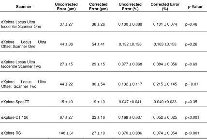
positions. The correction factors are then applied to images of a second validation
phantom to evaluate their ability in reducing the geometric error of images independently
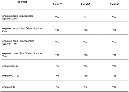
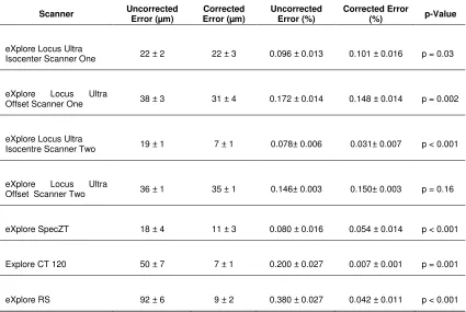
of the calibration phantom. The calibration phantom is used to characterize the
geometric accuracy of five different CT scanners representing four different
micro-CT models. Statistical analysis is performed to evaluate the performance of the
calibration phantom and to describe the nature of the geometric errors encountered.
1.8.2
Chapter 3: 3D Image-Guided Robotic Needle Positioning
System for Small Animal Interventions
This chapter describes the design, construction, characterization and biomedical
application of a micro-CT guided small animal needle positioning system. The
mechanical design of the system is based upon a spherical linkage previously used in
clinical applications [18]. The spherical linkage design is compact enough to allow the
robot to perform interventions entirely within the micro-CT bore. A method to calibrate
the robot needle is introduced which greatly reduces the time requirements of calibration
compared to previous designs. A dual mode registration process is introduced to
integrate the robot with a micro-CT scanner. The dual registration modes allow the user
depending on the specific application. The targeting accuracy of the robot is then
characterized using tissue-mimicking phantoms. Finally, use of the robot for a selected
References
[1] Y.S. Kowh, J. Hou, E.A. Jonckheere and S. Hayati, “A robot with improved
absolute positioning accuracy for CT guided stereotactic brain surgery,” IEEE
Trans. Biomed. Eng., 35(2), 153-160 1988.
[2] V. Horsley and R. H. Clarke, “The structure and function of the cerebellum
examined by a new method,” Brain, 31(1), 45–124, 1908.
[3] B. Davies, “A review of robotics in surgery,” Proc. Inst. Mech. Eng. H J. Eng.
Med., 214(1), 129-140 (2000).
[4] N.G. Hockstein, C.G. Gourin, R.A. Faust, D.J. Terris “A History of robots: from
science fiction to surgical robotics,” J. Robotic Surg., 1(2), 113-118, 2007.
[5] Intuitive Surgical Inc., 2010 Annual Report, February, 2011.
[6] K.B. Stitzenberg, Y. Wong, M. E. Nielsen, B.L. Egleston and R.G. Uzzo, "Trends
in Radical Prostatectomy: Centralization, Robotics, and Access to Urologic
Cancer Care," Cancer, In Press, 2011.
[7] R. H. Taylor and D. Stoianovici, “Medical Robotics in Computer-Integrated
Surgery,” IEEE Trans. Robot. Autom., 19(5), 765–781, 2003.
[8] D.B. Camarillo, T.M. Krummel and J.K. Salisbury, “Robotic technology in
surgery: past, present and future,” Am. J. Surg., 188 (Suppl to October 2004),
2s-15s, 2004.
[9] P. Dario, B. Hannaford and A. Menciassi, “Smart Surgical Tools and Augmenting
Devices,” IEEE Trans. Robot. Autom., 19 (5), 782- 792, 2003.
[10] J.R. Adler Jr, M.J. Murphy, S.D. Chang and S.L. Hancock, “ Image-guided
[11] R.H. Taylor, B.D. Mittlestadt, P.W. Hanson, P. Kazanzides, J.F. Zuhars, W. Williamson, B.L. Musits, E. Glassman and W.L. Bargar, “An Image-Directed
Robotic System for Precise Orthopaedic Surgery,” IEEE Trans. Robot. Autom.,
10(3), 261-275, 1994.
[12] A.P. Schulz, K. Seide, C. Queitsch, A. Von Haugwitz, J. Meiners, B. Kienast, M.
Tarabolsi, M. Kammal and C. Jürgens, “Results of total hip replacement using the Robodoc surgical assistant system: clinical outcome and evaluation of
complications for 97 procedures,” Int. J. Robotics Comput. Assist. Surg., 3(4),
301-306, 2007.
[13] G. S. Guthart and J. K. Salisbury, “The intuitive telesurgery system: Overview
and application,” Proc. IEEE Int. Conf. Robotics and Automation, 2000, pp.
618-621.
[14] C.H. Kuo and J.S. Dai in International Symposium on History of Machines and
Mechanisms, edited by H.S. Yan and M.Ceccarelli (Springer, Netherlands, 2009), pp. 337-354.
[15 ] R.H. Taylor, J. Funda, B. Eldridge, K. Gruben, D. LaRose, S. Gomory, M. Talamini, L.A. Kavoussi and J.H. Anderson, "A telerobotic assistant for
laparoscopic surgery," IEEE EMBS Mag., 14(3), 279-291, 1995.
[16] L. Yang, C.B. Chng, C.K. Chui and D.P.C. Lau, “Remote center of motion in
minimally invasive surgery,” Proc. IEEE Int. Conf. Robotics and Automation ,
2010, pp. 84-89.
[17] K. Masamune, E. Kobayashi, Y. Masutani, M. S Suzuki, T. Dohi. H. Iseki and K. Takaura, “Development of an MRI-compatible needle insertion manipulator for
stereotactic neurosurgery,” J. Img. Guided Surg., 1(4), 242-248, 1995.
[18] J. Bax, D. Cool, L. Gardi, K. Knight, D. Smith, J. Montreuil, S. Sherebrin, C. Romagnoli and A. Fenster. "Mechanically assisted 3D ultrasound guided prostate
[19] J.F. Pritchard, M. Jurima-Romet, M.L.J. Reimer, E. Mortimer, B. Rolfe and M.N. Cayen, “Making better drugs: decision gates in non-clinical drug development,”
Nat. Rev. Drug Discov., 2, 542-553, 2003.
[20] ICH: International Conference On Harmonization Of Technical Requirements For
Registration Of Pharmaceuticals For Human Use, “Guidance On Nonclinical
Safety Studies For The Conduct OF Human Clinical Trials And Marketing Authorization For Pharmaceuticals”, Step 2 Version, 2008.
[21] G.C. Kagadis, G. Loudos, K. Katsanos K, S.G. Langer and G.C. Nikiforidis, “In
vivo small animal imaging: current status and future prospects,” Med. Phys.,
37(12), 6421-6437, 2010.
[22] G. Francia, W. Cruz-Munoz, S. Man, P. Xu and R.S. Kerbel, “Mouse models of
advanced spontaneous metastasis for experimental therapeutics,” Nat. Rev.
Cancer., 11, 135-141, 2011.
[23] M.L. Springer, R.E. Sievers, M.N. Viswanathan, M.S. Yee, E. Foster, W.
Grossman, and Y. Yeghiazarians. “Closed-chest cell injections into mouse
myocardium guided by high-resolution echocardiography,” Am. J. Physiol. Heart
Circ. Physiol., 289(3), H1307–14, 2005.
[24] C.R. Chu, C.H. Coyle, C.T. Chu, M. Szczodry, V. Seshadri, J.C. Karpie, M.M. Cieslak and E.K. Pringle, “In vivo effects of single intra-articular injection of
0.5% bupivacine on articular cartilage”, J. Bone Jt. Surg., 92(3), 599-608, 2010.
[25] F.E. Cone, S.E. Gelman, J.L. Son, N.E. Pease and H.A. Quigley, “Differential susceptibility to experimental glaucoma among 3 mouse strains using bead
viscoelastic injection,” Exp. Eye. Res., 91(3), 415-424, 2010.
[26] M. Urano, Y. Chen, J. Humm, J. A. Koutcher, P. Zanzonico, C. Ling, “Measurements of tumor tissue oxygen tension using a time-resolved luminescence-based optical OxyLite probe: comparison with a paired survival
[27] M. El-Ghamari, F. Bergmann, B.M. Schmied, J. Weitz, and A. Ulrich, “Islet
cells contribute to pancreatic carcinogenesis in an animal model,” Pancreas,
40(2), 242-246, 2011.
[28] M.V. Cespedes, C. Espina, M.A. Garcia-Cabezas, A. Trias, A. Boluda, M.T.
Gomez del Pulgar, F.J. Sancho, M. Nistal, J.C. Lacal, and R. Mangues, “Orthotopic microinjection of human colon cancer cells in nude mice induces
tumor foci in all clinically relevant metastatic sites,” Am. J. Pathol., 170(3),
1077–85, 2007.
[29] T. de la Cueva, A. Naranjo, E. de la Cueva, and D. Rubio, “Refinement of
intrathymic injection in mice,” Lab Anim., 36(5), 27–32, 2007.
[30] Committee On Recognition and Alleviation of Pain in Laboratory Animals,
National Research Council. Recognition and Alleviation of Pain in Laboratory
Animals, National Academies Press, Washington D.C., 2009.
[31] R. Blair-Handon, K. Mueller, and S. Hoogstraten-Miller, “An alternative method
for intrathymic injections in mice,” Lab Animal, 39(8), 246-252, 2011.
[32] E.V. Groman and C.P. Reinhardt, “Method to quantify tail vein injection
technique in small animals,” J. Am. Assoc. Lab Anim. Sci., 43(1), 35-38, 2004.
[33] G. Paxinos and K.B.J. Franklin, The Mouse Brain in Stereotaxic Coordinates,
Elsevier Academic Press, New York, 2008.
[34] D. Wahlsten, W. J. Hudspeth, and K. Bernhardt, “Implications of genetic variation in mouse brain structure for electrode placement by stereotaxic
surgery,” J. Comp. Neurol., 162(4) , 519–31, 1975.
[35] G. Paxinos, C. Watson, M. Pennisi and A. Topple, “Bregma, lamda and the interaural midpoint in stereotactic surgery with rats of different sex, strain and