A Broadband Omnidirectional Antenna Array for Base Station
Bo Wang1, *, Fushun Zhang1, Li Jiang1, Qichang Li2, and Jian Ren1
Abstract—A high gain wideband antenna array with an omnidirectional radiation pattern is presented for base station. The antenna array is composed of four elements and a circular four-way power divider. The proposed planar antenna element consists of four pairs of arc dipoles and a balun, which can achieve a better impedance match and a wider frequency range. Furthermore, the conductor ground of the power divider with a larger size than the element is placed under the four antennas, which can also enhance the peak gain. The antenna array is simulated, fabricated and measured. The measurement results show that the proposed antenna array can achieve a bandwidth from 1.62 GHz to 2.43 GHz or a relative bandwidth of 39.4%. The antenna array has a peak gain of 6.4–7.2 dBi in the work band and obtains a radiation efficiency of 88%. The simulated and measured results show that the proposed antenna array is a good candidate as a base station antenna for GSM, PCS, and UMTS applications.
1. INTRODUCTION
With the increasing demand for and significant progress on the wireless communication industry, some features of antenna are required such as easy fabrication, broad bandwidth and specific radiation pattern [1]. Moreover, an omnidirectional radiation in the azimuthal plane and a narrow-beamwidth radiation in the elevation plane is usually required for base station wireless communications [2]. In other words, a high gain and omnidirectional antenna is suitable for the base station due to the fact that they can transmit and receive wireless signals identically. At the same time, a broadband antenna is required in base station of modern communication system [3], which means multifunction and simplicity. An antenna possessing the omnidirectional radiation pattern, high gain and broad bandwidth is required for improving communication performances and increasing the system capability especially in multipath environments.
Over the past decades, a number of omnidirectional antennas have been developed. A classical antenna consists of four dipoles on an annular substrate is proposed in [1] which has a bandwidth of 2.3–2.7 GHz. A printed dipole with parasitical strips is studied in [4, 5] that can operate over bands from 5.1 GHz to 6.8 GHz and from 1.7 GHz to 2.7 GHz, respectively. Several kinds of vertically polarized antenna arrays [6–8] have been published. However, the VP (vertical polarization) of the propagating electromagnetic wave changes significantly with complicated multiple reflections or scatterings [9]. In [10], a horizontal polarized omnidirectional antenna array with 8 elements is proposed. Its bandwidth is 34% and its peak gain is 8 dBi. A HP omnidirectional antenna array using zero phase-shift-line loop elements is proposed in [11], its bandwidth covers a frequency range of 2.35–2.55 GHz or a percentage bandwidth of 8% and its peak gain is about 6 dBi. A HP Omnidirectional antenna array employing artificial mu-negative transmission line loop as its element is proposed in [12], which can operate over WLAN band of 2.3–2.6 GHz. However, none of the above-mentioned omnidirectional designs can provide an antenna that achieves high gain and broadband patterns simultaneously.
In this paper, a broad bandwidth and high gain antenna with omnidirectional radiation pattern is presented. The antenna array consists of a feed network and four elements with four pairs of arc printed
Received 27 August 2014, Accepted 11 October 2014, Scheduled 20 October 2014
* Corresponding author: Bo Wang ([email protected]).
dipoles. Four coaxial lines with the same length are employed to connect the feed network and the elements. The operation bands cover the GSM, PCS and UMTS bands. By placing the conductor ground of the microstrip feed network under the array, the gain obtains a further enhancement and reaches 6.4–7.2 dBi. Due to the omnidirectional radiation characteristic of the element, the array achieves a full coverage in the azimuthal plane.
2. ANTENNA ELEMENT 2.1. Antenna Design
The configuration of the broadband antenna is shown in Figure 1. It consists of four pairs of arc dipole and tapered transmission lines connecting to the dipoles for impedance matching. The top and the bottom of the substrate are the same except the central circular patches. The two arc structures close to the slot are the two arms of the dipole antenna. The substrate has a relative permittivity of 4.4 with a thickness of 2.0 mm. The dipole antennas are connected to four tapered strip lines, respectively.
As shown in Figure 1, the antenna has a symetrical structure, thus a full coverage radiation results. The antenna is fed by a 50-Ω coaxial cable with an SMA connector at the center of the antenna. The outer conductor of coaxial cable is connected to the central circular patch on the bottom of the substrate and the inner conductor is linked to the top plane. The top central circular patch, the bottom central circular patch and the tapered lines act as a balun used for unbalance-balance transformation from coaxial cable to the arc dipoles. In the middle of the dipole edge, a rectangular slot is cut off the dipole arms to obtain an input impedance adjustment. Table 1 lists the design parameters of the proposed antenna.
From Figure 1(a), it can be seen thatLsis the length of the rectangular slot. As shown in Figure 2, with Ls increasing, the two resonant frequencies determined by the length of the two arc edges of the dipoles get separating. And the high frequency obtains a better impendence matching.
As shown in Figure 1(a), the increase ofB and R4 will also make the radiation part bigger in size
and the resonant frequency will get lower. It should be mentioned that the two resonant frequencies also can be separated by the increasing ofB, which leads to a deeper length gap. At the same time, it is found that when the thickness is expanding, the resonant frequency will get lower. It is mainly caused
(a) (b)
Figure 1. Configuration of the proposed dual-polarized patch antenna. (a) Top view. (b) Bottom view.
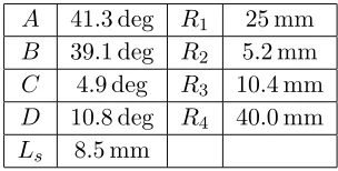
Table 1. Geometry parameters of the proposed antenna.
A 41.3 deg R1 25 mm
B 39.1 deg R2 5.2 mm
C 4.9 deg R3 10.4 mm
D 10.8 deg R4 40.0 mm
by the decrease of impedance imaginary part under the thickness increase. Many other parameters do not have so much effect on the electric performance as those above, so we do not make a further discussion.
2.2. Results
The simulated and measuredS-parameters of the antenna element are plotted in Figure 2(b), and they suggest that there is little difference between the measured and simulated results. As observed, the measured impendence bandwidth for return loss (RL)>10 dB achieves a frequency range from 1.7 GHz to 2.4 GHz, which indicates a percentage bandwidth of 34.1% for the proposed antenna.
(a) (b)
Figure 2. (a) Simulated S11 of the proposed antenna element with different Ls. (b) Simulated and
measured return loss for the proposed antenna.
(a) (b) (c)
(d) (e) (f)
Figure 3 illustrates the simulated and measured radiation patterns of the antenna in two principal planes,E-plane (xz-plane) andH-plane (xy-plane) at three different frequencies. As shown, the antenna has a full coverage radiation pattern in the azimuthal plane with 3 dB variation. It has a radiation gain over 1.7 dBi in the operating band.
3. BROADBAND OMNIDIRECTIONAL ANTENNA ARRAY
The base station antenna usually has a narrower beam width to achieve a higher gain. The proposed four-element antenna array can obtain a higher gain for GSM1800, GSM1900 and UMTS communication.
3.1. Array Geometry
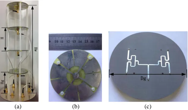
Figure 4 illustrates the geometry of the proposed broadband omnidirectional high gain four-element antenna array. It is fed by a circular four-way power divider, which is placed underneath the array with a distanceHg of 85 mm. Four same length coaxial lines are employed to connect the power divider with the elements. Before the element spacing increases to 120 mm (0.8λ0), the array gain rises withHrising
substantially.
(a) (b) (c)
Figure 4. A prototype of the four-element broadband omnidirectional antenna array. (a) The antenna array. (b) The antenna element. (c) The power divider (the array hightHw = 390 mm, the array width
Dg= 140 mm,Hg = 85 mm,H = 100 mm).
As shown in Figure 5, with the elements spacing H chosen as 60, 80, 100, 120, and 150 mm (λ0 = 150 mm), the array gain is 4.9, 5.5, 7.2, 7.7 and 7.8 dBi at 2 GHz, respectively. Under the
consideration of the array height, H= 100 mm is an acceptable compromise.
3.2. Results
The proposed antenna array is fabricated and measured. The photograph of the prototype is depicted in in Figure 4. The simulated and measured reflection coefficients (S11) of the proposed antenna element
and array are plotted in Figure 6. As observed, the measured impedance bandwidth of the array for return loss (RL) > 10 dB achieves a frequency range from 1.62 GHz to 2.43 GHz or a percentage bandwith of 39.4%.
Figure 5. The peak gain of the antenna array with different H.
Figure 6. Simulated and measured return loss for the proposed antenna element and array.
(a) (b) (c)
(d) (e) (f)
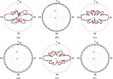
Figure 7. Simulated and measured radiation patterns of the fabricated antenna. (a) xz-plane at 1.62 GHz. (b)xy-plane at 1.62 GHz. (c)xz-plane at 2.0 GHz. (d)xy-plane at 2.0 GHz. (e)xz-plane at 2.43 GHz. (f)xy-plane at 2.43 GHz.
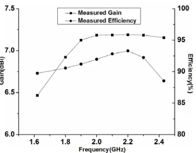
Figure 8. Measured gains and efficiency of the proposed antenna array.
Table 2. Comparison of various omnidirectional antenna.
```````````
References
Items
10-dB
impedance
bandwidth
Peak
gain
(dBi)
Dimension
(λ0 at medium
frequency)
εr Elements
number
Unit
Wideband
antenna [5] 41% 4.2 0.47λ0×0.47λ0×0.02λ0 4.4
-MNG-TL
array [12] 5.7% 2.3 0.4λ0×0.4λ0×0.005λ0 2.65
-Broadband
HP array [10] 31% 1.37 0.65λ0×0.65λ0×0.005λ0 3.55
Proposed
antenna 34.1% 1.7 0.53λ0×0.53λ0×0.013λ0 4.4
-Array
Slot
array [6] 4.6% 10 4.7λ0×0.29λ0×0.04λ0 2.65 8
Dipole
array [7] 12% 6.1 1.44λ0×0.15λ0×0.003λ0 4.4 2
MNG-TL
array [12] 10.6% 7.9 0.4λ0×0.4λ0×3.25λ0 2.65 4
Broadband
HP array [10]
34% 8 1.1λ0×1.1λ0×7.1λ0 3.55 8
Proposed
array 39.4% 7.2 0.9λ0×0.9λ0×2.6λ0 4.4 4
and measurement. Simultaneously, the peak gain has a little enhancement. As Figure 8 shown, the peak gains of the proposed antenna over the whole operating band are 6.4–7.2 dBi, which are stable and acceptable. The simulated radiation efficiency is around 88% over the entire operational band of 1.62–2.43 GHz.
4. CONCLUSIONS
In this paper, a novel wideband omnidirectional high gain antenna array is proposed for base station wireless communication. Furthermore, the proposed antenna array is fabricated and measured. The proposed antenna array achieves a percentage impedance bandwidth of 39% (1.62–2.43 GHz) with a return loss of greater than 10 dB and covers GSM/PCS/UMTS frequency bands. Besides, omnidirectional radiation patterns are obtained with enhanced gains of 6.4–7.2 dBi. With the advantages of easy fabrication and light-weight, the proposed antenna array is a good candidate as a base station antenna.
REFERENCES
1. Chen, J. Y., X. M. Zhang, X. W. Dai, C. B. Zhang, and C. Jiang, “A broadband dual-polarization ceiling-mounted antenna with a nesting structure,”Proc. ISSSE, Vol. 2, 1–3, 2010.
2. Herscovici, N., Z. Sipus, and P.-S. Kildal, “The cylindrical omnidirectional patch antenna,” IEEE Transactions on Antennas and Propagation, Vol. 49, No. 12, 1746–1753, Dec. 2001.
3. Quan, X. and R. Li, “A broadband dual-polarized omnidirectional antenna for base stations,”IEEE Transactions on Antennas and Propagation, Vol. 61, No. 2, 943–947, Feb. 2013.
4. Zhang, G. G., H. Zhang, Z. L. Yuan, and Z. M. Wang, “A novel broadbandE-plane omnidirectional planar antenna,”Journal of Electromagnetic Waves and Applications, Vol. 24, Nos. 5–6, 663–670, 2010.
5. Yu, Y., F. Jolani, and Z. Chen, “A wideband omnidirectional horizontally polarized antenna for 4G LTE applications,”IEEE Antennas and Wireless Propagation Letters, Vol. 12, 686–689, 2013. 6. Chen, X., K. Huang, and X.-B. Xu, “A novel planar slot array antenna with omnidirectional
pattern,”IEEE Transactions on Antennas and Propagation, Vol. 59, No. 12, 4853–4857, Dec. 2011. 7. Wong, K., F. Hsiao, and T. Chiou, “Omnidirectional planar dipole array antenna,” IEEE
Transactions on Antennas and Propagation, Vol. 52, No. 2, 624–628, Feb. 2004.
8. Oh, J. and K. Sarabandi, “Low profile vertically polarized omnidirectional wideband antenna with capacitively coupled parasitic elements,”IEEE Transactions on Antennas and Propagation, Vol. 62, No. 2, 977–982, Feb. 2014.
9. Chizhik, D., J. Ling, and R. A. Valenzuela, “The effect of electric field polarization on indoor propagation,” IEEE 1998 International Conference on Universal Personal Communications, ICUPC’ 98, Vol. 1, 459–462, Oct. 5–9, 1998.
10. Quan, X. L., R. L. Li, J. Y. Wang, and Y. H. Cui, “Development of a broadband horizontally polarized omnidirectional planar antenna and its array for base station,” Progress In Electromagnetics Research, Vol. 128, 441–456, 2012.
11. Qing, X. and Z. N. Chen, “A compact metamaterial-based horizontally polarized omnidirectional antenna array,” 2013 IEEE Antennas and Propagation Society International Symposium (APSURSI), 1792–1793, Jul. 2013.