MILLENNIUM INFORMATION SYSTEMS ,INC.
UNIVERSAL ONE
Microco~er
Development System
UNIVERSAL ONE
Microco~er
Development System
Operators
Gllide
Document No. U01-0000-21 Issued Nov. 1976
MILLENNIUM INFORMATION SYSTEMS ,INC.
DOCUMENT NO. U01-0000-21
PRICE - $35.00
Copyright 1976, Millennium I nformation Systems, I nco All rights reserved.
Table of Contents
Paragraph
CHAPTER INTRODUCTION
1 .1 1.2 1.3
Objectives of a Microcomputer Development System Universal One Overview
About Th is Book. . . .
CHAPTER 2 SYSTEM DESCRIPTION
2.1 Introduction...
2.2 Hardware...
2.2.1 Development Computer
2.2.2 Emulation Hardware .
2.2.3 Dual Floppy Disk Subsystem
2.2.4 Peripherals...
2.2.5 User-Supplied Peripherals .
2.3 S o f t w a r e . . .
2.3.1 UDOS (Universal Disk Operating System)
2.3.2 The Debugger . . .
2.3.3 PROM Programming
2.3.4 The Editor . . . .
2.3.5 The Assemb ler. . .
2.3.6 Systems Readiness Test
CHAPTER 3 SYSTEM INSTALLATION AND OPERATION
3.1 I n t r o d u c t i o n . . . .
3.2 U n p a c k i n g . . .
3.2.1 Unpacking the Universal One Development Computer.
3.2.2 Unpacking the CRT Terminal . .
3.2.3 Unpacking the Floppy Disk Unit.
3.2.4 Unpacking the Line Printer. .
3.2.5 Installing the Emulation Cable. . 3.3 Physical Installation. . . .
3.3.1 Power and Cable Interconnections
3.3.2 Controls and Indicators
3.3.3 Development Computer . . . .
Table of Contents (Cant.)
Paragraph
3.3.4
3.3.5
3;3.6
3.4
3.4.1
3.4.2
3.4.3
Dual Floppy Disk Unit CRT Terminal
Line Printer. . . . . Operation . . . .
Formatting and Verifying New Diskettes. System Startup Procedure
Manual Reset . . . .
CHAPTER 4 UNIVERSAL DISK OPERATING SYSTEM
4.1
4.2
4.2.1
4.2.2
4.34.4
4.5
4.5.1
4.5.2
4.5.3
4.5.4
4.6
4.6.1
4.6.2
4.6.3
4.6.4
4.6.5
4.6.6
4.6.7
4.6.8
4.6.9
Introduction . . . . UDOS Overview . . . . . Resident U DOS Modu les . UDOS Overlays . . . . Files, Devices, and Channels Entering UDOS Commands. Special Keys
Delete Key Escape Key Space Bar.
CTR L-Z Command The U DOS Commands.
The UDOS Command Structure U DOS Command Completion System Control Commands. System Option Commands . System Utilities Commands. Object Program Uti I ity Commands Command Files . . .
Command File Utilities U DOS Error Messages .
Table of Contents (Cont.)
Paragraph
CHAPTER 5 THE DEBUGGER
5.1
5.2
5.3
5.4
5.5Introduction . . . . The Debug Program. . . . Invoking the Debugger. . .
Sample Debug Session (Using a 2650 Slave) Debug Commands . . . .
CHAPTER 6 THE EDITOR
6.1
6.2
6.36.4
6.5
6.5.1 6.5.26.5.3
6.5.4
6.5.5 6.5.66.5.7
6.5.8
6.5.9
6.5.106.6
IntroductionEditor Overview . . . U DOS Command Edit. Edit Example . . . . Editor Command Descriptions
Editor Command Line
Editor Command Description Conventions . I nsertion Commands .
Deletion Commands Alteration Commands . Search Commands . . I/O Commands
Buffer Line Pointer Commands Utilities . .
MARCROS . Editor Messages
CHAPTER 7 THE ASSEMBLER
7.1
7.27.3
7.4
7.5
IntroductionAssembler Overview. . . . . Using the Assembler . . . . Loading An Assembled Program Sample Assembly Listing. . .
Table of Contents (Cont.)
Paragraph
CHAPTER 8 PROM PROGRAMMER
8.1
8.2
8.3 8.4Introduction . . . . PROM Programming Hardware and Software Using the PROM Programmer .
PROM Programmer Commands . . . -. .
CHAPTER 9 SUPERVISOR CALL INTERFACE
9.1
I n t r o d u c t i o n . . .9.2
General Description of Supervisor Calls9.3
Service Request Block (SRB) .9.3.1
SRB Bytes . . . .9.3.2
SVC Function Descriptions.APPENDIX A APPENDIX B APPENDIX C APPENDIX D APPENDIX E APPENDIX F APPENDIX G APPENDIX H
UDOS COMMAND SUMMARY DEBUGGER COMMAND SUMMARY EDITOR COMMAND SUMMARY SVC FUNCTION CODES
SRB STATUS CODES SMS TAPE FORMAT
SYSTEM READINESS TEST
SYSTEM UTILITY COMMAND FILES
Page
8-1 8-1 8-1
8-2
list
of Ilustrations
Figure
Page
1-1
The UNIVERSAL ONE Microcomputer Development System1-0
1-2
General Block Diagram of a Microprocessor-based Product.1-3
2-1
Overall Block Diagram of the UNIVERSAL ONE . .2-2
2-2
Data Organization on a Diskette . . .2-6
3-1
Development Computer Printed Circuit Board Layout3-2
3-2
Development Computer (Top View) . . .3-3
3-3
Envelope Dimensions of System Units. . .3-5
3-4
Typical Cabling Diagram of UNIVERSAL ONE System Installation3-6
3-5
Front Panel of the Development Computer.3-8
3-6
Rear Panel of the Development Computer3-9
3-7
Rear Panel of the Floppy Disk Drive . . .3-10
3-8
Inserting a Diskette. . .3-11
5-1
Displays During Sample Debugging Session .5-4
5-2
Typical Displays During Various Debugging Modes.5-8
6-1
A Sample Source Program . . .6-3
6-2
Entering Text and Display the Buffer . . .6-5
6-3
Use of FIND, SUBSTITUTE and REPLACE Commands.6-6
6-4
Displaying the Buffer and Filing . . .6-6
6-5
Sample Double Precision Add and Subtract Programs.6-7
6-6
Adding Data to an Existing File . . .6-9
6-7
Inserting Lines Into the Buffer . . .6-11
7-1
Sample2650
Slave Program Listing Ready for Assembly.7-4
7-2
Sample2650
Slave Assembly Listing . . .7-5
Chapter
Introduction
1.1 OBJECTIVES OF A MICROCOMPUTER DEVELOPMENT SYSTEM.
In the development of any product that includes a microprocessor, there are aspects which have no parallel either in random logic design or in computer program develop-ment (the two predecessors of microprocessor product developdevelop-ment).
There is no clear cut demarcation between logic which should be implemented using random logic hardware, or logic which should be implemented with programmed instructions; that is what makes microprocessor product development unique. A successful microcomputer development system, such as UNIVERSAL ONE, must therefore support digital logic development and program creation with equal ease.
If in addition, the product or series of products can benefit from the use of different microprocessors, a single universal hardware and software development system, of the configuration of UNIVERSAL ONE, has several easily recognizable advantages:
1. It eliminates the cost of another development system each time a new micro-processor is to be implemented.
2. It providesa common system for all development, thus eliminating heavy investments in personnel training and software for multiple systems.
3. It frees the designer to consider any microprocessor-solely on the basis of its capabilities and cost-effectiveness, rather than because the designer is locked into a microprocessor from a previous product commitment.
1.2 UNIVERSAL ONE OVERVIEW.
1.2.1 Master/Slave Concept. UNIVERSAL ONE, achieves the required
uni-versality by dividing its operations into two functional areas. Those tasks that are related to the development system itself are assigned to a master central processing unit, and those that are prototype-related are assigned to a second, slave CPU. As many as four different slaves may be installed simultaneously and individually invoked with a corresponding slave diskette. This mUltiple architecture enables the hardware to support a particular microprocessor with the addition of a printed circuit card containing the corresponding slave CPU. Since the master processor need not be changed to accommodate new slave units, all of the operating system software remain the same.
The master CPU is responsible for all system services that are not prototype-dependent, such as:
• File management - the storage and retrieval of data and programs.
• Text editor - maintains text files in the floppy disk.
• System input/output - the normal I/O activities between the standard system peripherals, such as the floppy disk, line printer, and system control console.
• System utilities, including programming of PROMs for the final version of the prototype.
• Debug functions - the master executes the debug software and controls the slave through a separate debugging hardware module.
The slave CPU's functions include:
• Program assembly - each slave may be used as a resident assembler of proto-type programs.
• Prototype program execution - the prototype program is loaded into the slave memory and executed by the slave.
• Prototype I/O - any special input/output required in the prototype can be performed by the slave, without involving the master CPU.
• I n-circuit emulation - a cable extends from the slave to the CPU socket in the prototype.
1.2.2 System Functions. UNIVERSAL ONE may at first look like any other general purpose minicomputer system; because there is a terminal which communicates with a box that resembles a minicomputer, results may be created on a line printer, and intermediate data or programs may be stored on diskettes.
Indeed, UNIVERSAL ONE offers many of the program creation and execution facilities that any general purpose minicomputer system will offer. Source programs, written in assembly language, may be entered via the terminal and stored on diskette. Subsequently, source programs may be retrieved from diskette, edited and stored back. An Assembler converts source programs into executable object code and a Debugger allows the object code to be conditionally executed for the purpose of detecting conceptual errors - - that is, instruction sequences which, though they are syntactically correct, do not accurately represent the intended logic or data flow.
Introduction
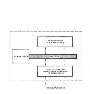
But UNIVERSAL ONE is much more than a general purpose minicomputer. The typical microprocessor user program created on UNIVERSAL ONE is subsequently going to becomean object program, implemented in PROM or ROM. A microprocessor object program is therefore ultimately to become a package, driving microprocessor-based logic, in a configuration that may not even remotely resemble a computer. The only constant that may be ascribed to these products is that they will contain a microprocessor, driven by one or more object program packages; additional logic must be present to handle the flow of data or signals to or from the microprocessor. Figure 1-2 therefore generally identifies the ultimate configuration which any micro-processor-based product will have.
1.2.3 System Capabilities. Every part of the end product illustrated in Figure
1-2 may be developed using UNIVERSAL ONE.
The process of creating an executable object program was discussed first, since this is the most obvious capability of a system th~t looks like a general purpose mini-computer. But the similarities between UNIVERSAL ONE and a general purpose
,---,
I
I
OBJECT PROGRAMS
I
I
IN ROM, RAM, OR PROMI
I
I
I
I
I
I
MICROPROCESSORI
I
I
I
I
INTERFACE LOGIC FOR
I
I
SIGNALS AND DATA EXCHANGEI
TO OUTSIDE WORLDI
L________ ___ _ __
J
INPUT/OUTPUT SIGNALS
Figure 1-2. General Block Diagram of a Microprocessor-based Product
minicompute~ end at this superficial level. Consider some of the additional features which UNIVERSAL ONE provides to serve as a total microprocesosr-based product development aid.
To begin with the UN IVERSAL ONE provides at least two CPUs. The master CPU performs monitoring and disk operating system functions; functions required by UNIVERSAL ONE, but absent in the product being developed. The slave micro-processor takes the place of the device which must be present in the end product.
Memory is also provided in duplicate. The master CPU has its own memory, out of which it can execute·.monitoring and disk operating system programs. The slave CPU has a separate memory which remains· available to simulate· prototype memory, for user application programs. When appropriate, the master CPU accesses slave processor memory. The master and slave memories can be initially viewed as separated for system use and for application or user use.
Because object programs are likely to be stored in PROM or ROM devices. UN
1-VERSAL ONE allows you to create the PROM, or to define the ROM mask.
Simulation of the I/O logic shown in Figure 1 ~2 remains to be described. The problem with this additional logic is that it is completely undefinable. Not only is it impossible to say how far such logic migrates into an end product, it is equally hard to determine, in advance, those functions which will end up as program steps in mel'Dory, as opposed to random logic. UN IV E RSAL ON E resolves the open-ended ness of this additional logic by providing the emulation cable. Any external logic may communicate with the slave microprocessor and its slave memory via this cable. Moreover, external logic beyond the emulation cable may, itself, contain program memory.
Thus, UNIVERSAL ONE becomes a total microprocessor-based product development system. Every aspect of a microprocessor-based product may be simulated and designed using UNIVERSAL ONE. Object programs which, while being created, are executed by a microprocessor which is identical to the end product microprocessor. While object programs were executed by UNIVERSAL ONE, during their creation, they interacted via the emulation cable with additional logic which, package-for-package, will be identical to the eventual end product. Therefore, when going from emulation to end product, the only changes wi II be in physical fabrication.
1.3 ABOUT THIS BOOK.
This book is a UNIVERSAL ONE Operator's Guide. As such, it describes all aspects of UN IVERSAL ONE system operation, from unpacking, through switches and indicators, to the use of the various system development programs.
Introduction
Each microprocessor supported on UNIVERSAL ONE system is provided with a manual supplement describing the software and hardware peculiar to that micro-processor.
Chapter 2 of this manual describes system hardware in general terms, and gives an overview of system software. Chapter 3 describes unpacking, installation, and initial operation; Chapter 4 gives details about the Universal Disk Operating System and describes procedures for using it; Chapter 5 describes the emulation and the debug capabilities of the UN IVERSAL ONE system and explains all Debugger commands; Chapter 6 describes the Text Editor and gives procedures for using the Editor to create and modify files; Chapter 7 describes how the Assembler is used to create object programs from assembly language programs; Chapter 8 gives procedures for programming type 1702A and type 82S115 PROMs from assembled user programs; and Chapter 9 describes Supervisor Calls (SVCs), with which any slave CPU program can communicate with system peripherals.
Chapter
2.1 INTRODUCTION.
System
Description
This chapter outlines system configuration, peripherals, and software provided with the system.
2.2 HARDWARE.
The UN IVERSAL ONE is a complete microcomputer development system. This system is used to create and edit assembly language source programs, to assemble source programs into object code, and" to·execute object programs. User's object programs may be executed out of UNIVERSAL ONE memory, or by using the emulation interconnecting cable assembly, object programs may be executed out of external memory that is part of an end product. Thus UNIVERSAL ONE can simulate an end product, or interface directly to it, and has the ability to support every phase of product development. A UN I VE RSAL ON E system consists of a development computer with 16 K bytes of master memory and 16 K to 65 K bytes of slave (or common master/slave) memory, and a dual drive floppy disk unit; peripherals include a terminal and a line printer. Options available include additional floppy disk units, additional memory, PROM programmers, and general purpose I/O cards. The computer, disk unit, terminal., and line printer are all desk-top units and are self-contained.
2.2.1 Development Computer.
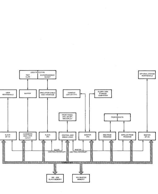
The development computer consists of a mainframe enclosure and printed circuit boards. I n addition to the basic CPU and memory boards, optional boards can be added to implement a particular development function. The following paragraphs describe major functions of the development computer hardware and Figure 2-1
shows a block diagram of it.
Master and Slave CPUs. The UNIVERSAL ONE operating system (UDOS) and the
Text Editor run under the master CPU. The Assembler, other system programs, and user programs all run on the slave CPU.
I
2-2
USER PRClTOTYPE
I
TEST ,I
MICROPROCESSOR CLIPS SOCKETFLOPPY DISK STORAGE SUBSYSTEM
I
CONSOLE'1-
~
(CRT OR TTY)I
n
~---~ ~---~
I
FRONT PANELI
STD, OR OPT, SW-DISPLAYSLAVE CONTROL/INTERRUPT
I
16K-65KI
SLAVE MEMORYMASTER CONTROL/INTERRUPT
16 K MASTER MEMORY
I
PROM SrCKETSFigure 2-1. Overall Block Diagram of the UNIVERSAL ONE
I
System Description
Partitioned I/O. The master CPU handles all I/O communication with system peri-pherals. Programs executed by the slave CPU communicate with system peripherals via the master CPU by issuing requests to the master CPU for their system I/O. This is done through supervisor calls (SVCs) from the slave to the master. SVCs are discussed in Chapter 9.
There is separate interface logic available only to the slave CPU. Using this logic, the user can add interface boards for development-oriented peripherals, allowing the slave CPU to communicate with its own peripheral units directly. Thus, programs under development can be executed in hardware environment making full use of the users prototype resources, including I/O logic, power supplies, etc.
Dual Memories. The system includes two separate memories: one is the slave memory of up to 65K bytes. This memory is accessible by both master and slave CPUs. Two system programs, the Assembler, plus a small Debug trace package, are executed out of the slave memory by the slave CPU. User development programs are also run by the slave CPU from this memory. (The Editor is run out of slave memory by master CPU.)
The other memory is the master memory from which the operating system and the Debug monitor are run by the master CPU. This memory is protected completely from the slave CPU and its application programs. The protected portion has an address range from 0000 through 16383. The master CPU also has the ability to map anyone 16K section of the slave memory into an additional address space available only to the master. This allows the master CPU access to user buffers and pointers used for supervisor calls (SVCs).
Having separate master and slave memories ensures that the operating system need not interfere with user programs. This also protects the integrity of the operating system in the master memory so that it cannot be inadvertently affected by develop-ment programs.
PROM Programming. The development computer contains two optional PROM programming boards and three front-panel PROM sockets. Unique programming boards are used for the 82S115 bipolar PROM and the 1702A MOS PROM. Programm ing of the PROMs is accompl ished under program control, after the user has a completely assembled and debugged program. A front panel switch turns off PROM programmer power, so that devices cannot be damaged during insertion and removal.
2.2~2 Emulation Hardware.
The emulation hardware consists of a cable and driver/receiver circuits that allow in-circuit emulation of user programs in user developed hardware. The user's micro-processor is removed and replaced by a cable plugged directly into the socket. The other end of the cable is attached to the UNIVERSAL ONE slave CPU circuit board, which contains multiplexing and other logic to support and discriminate between the UNIVERSAL ONE operating modes. The slave CPU thus can become the CPU for the user system.
Presently there are three modes of operation:
1) The slave CPU runs the program residing in slave memory using the I/O circuits contained in the UNIVERSAL ONE system. This is the normal non-emulation mode.
2) The slave CPU runs the program resident in slave memory, but all I/O signals and data are derived from external user developed hardware.
3) The slave CPU runs user programs resident in external user development memory. All I/O signals and data are derived from the user developed hard-ware.
The emulation cable contains an in-line printed circuit assembly (interface assembly) which provides isolation for the UN IVERSAL ONE system from the user system. The cable is approximately 10 feet long and has two connectors on one end (this end is attached to the slave CPU board) and a 40-pin plug on the other end (which is inserted into the user system). Refer to Chapter 3 for detailed installation instruc-tions.
The cable may remain installed even though not in use as long as care is taken not to short out the 40-pin plug. A 1 amp fuse on the slave CPU board protects the +5V power to the emulation cable.
The SLAVE command controls what signals are passed over the emulation cable to the user's prototype system.
2.2.3 Dual Floppy Disk Subsystem.
The floppy disk subsystem is the mass storage medium for the system. The disk subsystem consists of two disk drives, a microprocessor controller, power supplies, and cabinet. The two disk drives are designated as drive 0 and drive 1, and the disk subsystem communicates directly with the master CPU card in the development computer through an interconnecting cable.
Drive 0 is usually the system drive. That is, the diskette with the system programs is normally placed in this drive. The system drive is automatically accessed when a drive number is not specified with a file name. The diskette loaded on the system drive is known as the system diskette and normally contains all system programs, including UDOS, Editor and the Debugger peculiar to a specific slave on the four outside tracks. (The system diskette can be write protected to ensure that the system programs
System Description
are not altered.} Alternatively, any drive can be designated as the system drive by U DOS commands.
Drive 1 usually contains a second diskette utilized primarily for storing user files, for modifying user files, or as a scratch data area, and mayor may not contain the system programs. (If it does, the programs usually are duplicate of those on the system diskette.) This diskette, since it may be used as a scratch area, is not write protected.
Controller. The floppy disk controller utilizes a 128-byte sector buffer to allow asynchronous data transfer. Other important features include sector interleaving, automatic data blocking, automatic system boot on power-up, automatic retry on read or write failures, and the ability to expand to an eight drive system.
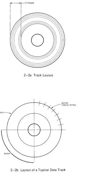
Diskette. The organization of data on a diskette is pictured in Figures 2-2a and 2-2b. On each diskette, there are 77 concentric tracks (Figure 2-2a), which can contain data. I n Figure 2-2b, a typical track is divided into its component parts. Each quarter track ;s referred to as a block. Each block is split into eight sectors. A sector is the basic unit of disk data. Each sector can contain 128 eight-bit bytes. Due to directory limitations, a maximum of 78 files can be contained on one diskette. The disc operating system reserves track 0 for the disc directory, and tracks one through four are normally automatically reserved for system programs.
I n order for the disk drive to be able to read or write a diskette, the diskette must have certain initial information on it. The process of placing this information on the diskette is called formatting. Diskettes must be formatted before use. (See paragraph 3-16).
2.2.4 Peripherals.
Optional peripherals compatible with the system include a CRT terminal with a full ASCII keyboard, a line printer, and a paper tape reader. In addition, an optional general purpose I/O card supports any RS-232-C compatible device and contains four 8-bit parallel I/O ports which allow the user to interface TTL compatible peripherals to the UNIVERSAL ONE.
CRT Terminal. The CRT terminal is the primary I/O device for the operator. The terminal consists of a CRT display and an operator keyboard. The keyboard is a standard typewriter-style unit with additional mode keys.
ASR-33 Teletypewriter. A standard ASR-33 with a 20 mA current loop or RS-232-C interface can be used as an alternate console I/O device. I n addition, the TTY can be used to provide hard copy and to punch paper tapes for file storage off line. (Note: because of its wide availability, Millennium Information Systems does not offer the TTY as an option, it should also be noted that the system will also drive a Silent 700 terminal).
t---_~77 TRACKS
o
2-2a Track Layout
2-2b Layout of a Typical Data Track
Figure 2-2. Data Organization on a Diskette
System Description
and is capable of printing 100 characters per second with an 80 character column width, or 165 characters per second with a 132 character column width.
2.2.5 User-Supplied Peripherals.
Any RS-232-C compatible peripheral can be connected to the serial I/O port of the General Purpose I/O card, or any 8-bit parallel device to one of the four parallel ports on the General Purpose I/O card. If these peripherals are to interface to the operating system, the addition of a software driver to control the device is required. This driver is added to the UNIVERSAL ONE software using the method described in the UNIVERSAL ONE System Reference Manual.
2.3 SOFTWARE.
The UNIVERSAL ONE development system software consists of an overall operating system, called UDOS (Universal Disk Operating System), and several more or less independent subordinate programs for specific functions: the Debugger, the Editor, the Assembler, the optional PROM Programmer, and a Systems Readiness Test program. Together, these are referred to as the system programs (as opposed to user or application programs generated by the user, stored in the slave memory and run entirely by the slave CPU, without involving the master CPU).
During operation U DOS resides in the master memory, but other programs reside in the slave memory (except a portion of the Debugger is in the master memory). The subordinate system programs are invoked by UDOS commands.
2.3.1 UDOS (Universal Disk Operating System).
U DOS provides the user with a variety of commands that allow the user to exercise the flexibility of the UNIVERSAL ONE system. UDOS provides commands that:
*
*
*
*
*
*
Perform disk and file maintenance Set the mode for I/O channels Perform system uti I ity functions
Allow the user to control execution of programs Display important system status
Manipulate and modify object code
These commands are described in more detail in Chapter 4.
There are two other features of UDOS that deserve mention. These are the Debug Monitor and the PROM programming capability. These are described in Chapter 5 and 8, respectively.
2.3.2 The Debugger.
of object programs while examining, changing or tracing the contents of memory, registers or system status.
All Debugger I/O functions are performed by UDOS. Due to the fact that the master CPU may not access the slave CPU registers directly, a small section of the Debugger is placed in slave memory to make slave CPU registers available to the Debugger for examination and modification. The Debug monitor executes in master memory.
2.3.3 PROM Programming.
UDOS provi'des a series of commands that allow PROMs to be read, written and compared with slave memory. All these commands apply to the PROM sockets located in the front panel.
2.3.4 The Editor.
After a source program is conceived and designed, it is input to the UN IVERSAL ONE system through the use of a program called the Editor, which will store a key-entered source program on the floppy disk. The Editor is also used to modify source programs that already exist on mass storage.
The Editor runs in slave memory using the master CPU. The 16 K segment of slave memory in which the Editor is located is also available as a text buffer for the data being operated on by the Editor (all 16K is available, less space occupied by Editor program). UDOS performs all the Editor's I/O requests.
2.3.5 The Assembler.
After a source program has been entered and stored on disk, it must be translated into a machine-executable object program. This function is performed by the Assembler, which stores the object code it has assembled from the source program on mass storage.
The Assembler runs in slave memory using the slave CPU. The Assembler uses the available part of slave memory for I/O buffers and to create its symbol tables. UDOS handles all the Assembler's I/O requests.
2.3.6 Systems Readiness Test.
The systems Readiness Test allows the user to insure that the UNIVERSAL ONE system is operational. This test is described in Appendix G.
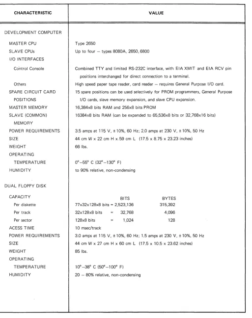
System Description Table 2-1. Performance Specifications and Leading Particulars
CHARACTERISTIC
DEVELOPMENT COMPUTER
MASTER CPU
SLAVE CPUs
I/O INTERFACES
Co'ntrol Console
Others
SPARE CIRCUIT CARD
POSITIONS
MASTER MEMORY
SLAVE (COMMON)
MEMORY
POWER REQUIREMENTS
SIZE
WEIGHT
OPERATING
TEMPERATURE
HUMIDITY
DUAL FLOPPY DISK
CAPACITY
Per diskette
Per track
Per sector
ACESS TIME
POWER REQUIREMENTS
SIZE WEIGHT OPERATING TEMPERATURE HUMIDITY VALUE
Type 2650
Up to four - types SOSOA, 2650,6800
Combined TTY and limited RS-232C interface, with EIA XMIT and EIA RCV pin
positions interchanged for direct connection to a terminal.
High speed paper tape reader, card reader - requires General Purpose I/O card.
15 spare positions can be used selectively for PROM programmers, General Purpose
I/O cards, slave memory expansion, and slave CPU expansion.
16,3S4xS bits RAM and 256xS bits PROM
163S4xS bits RAM (can be expanded to 65,536xS bits or 32,76Sx16 bits)
3.5 amps at 115 V, ± 10%,60 Hz; 2.0 amps at 230 V, ± 10%,50 Hz
44 cm W x 22 cm H x.59 cm L (17.5 x S.75 x 23.23 inches)
661bs.
to 90% relative, non-condensing
BITS
77x32x 12SxS bits = 2,523,136
32x12SxS bits = 32,76S
12SxS bits 1,024
10 msec/track
BYTES
315,392
4,096
12S
3.0 amps at 115 V, ± 10%,60 Hz; 1.5 amps at 230 V, ± 10%,50 Hz
44 cm W x 27 cm H x 60 cm L (17.5 x 10.5 x 23.62 inches)
S5lbs.
100
-3So C (500
-1000
F)
Chapter
3.1 INTRODUCTION.
System Installation
~
and Operation
This chapter describes unpacking, installation, interconnection, and initial operation of the system. Refer to the individual peripheral manuals provided for specific installation procedures for these units.
3.2 UNPACKING.
The system is shipped with each major unit in a separate carton. Before unpacking the units, inspect each carton for signs of external damage. If any damage is detected, make a note on the shipper's receipt.
3.2.1 Unpacking the Universal One Development Computer.
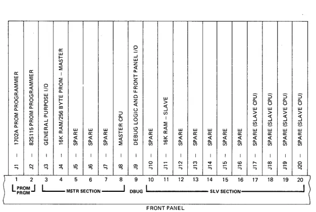
To unpack the development computer, open the carton and remove the unit from its packing supports. Place the computer on a bench top and remove the top cover. Remove the packing material from the printed circuit boards and install them in the proper card slots. The suggested position for each board is shown in Figure 3-1. The board connectors are offset to prevent them from being installed backwards. Push each board firmly into its motherboard socket. Untape and remove the power-on switch keys from the chassis and place in the key switch.
Connect the ribbon cable from the front panel to P3 on the debug logic card, the ribbon cable from J108 on the rear panel to P2 on the master CPU card, the ribbon cable from the left-most PROM socket on the front panel to P2 on the 1702A programmer card (if included in the system), and the ribbon cable from the center socket on the front panel to P2 on the 82S115 programmer card (if included in the system). Note that the red wire on each cable indicates the end of the cable to be connected to pin 1 of its mating connector. A top view of the computer unit with cards and cables properly installed is shown in Figure 3-2. Do not replace the top cover at this time.
3.2~2 Unpacking the CRT Terminal.
Open the carton and remove the packing material from the top of the unit. Lift the terminal and the keyboard out of the carton and set it on a bench top. No further action is required until the system is ready for interconnection and operation.
UJ ~
> u
::i UJ
(/J >
I ::i
:2: ~
UJ UJ UJ UJ <{ UJ UJ UJ UJ UJ UJ
a: a: a: a: a: a: a: a: a: a: a:
;;.: ;;.: ;;.: ;;.: ~ ;;.:
~ ;;.: ;;.: ;;.: ~ (/J (/J (/J (/J ~ (/J (/J (/J (/J
I I I I I I I I I I I I I I I I I I I I
M
'" .... ~ '"
E
~ '" ~ .... ~ ~ ~ ::; £; ...., :; ...., ~ ...., $l Ql ...., ....,)
1 2 3 4 5 6 7 8 9 10 11 12 13 14 15 16 17 18 19
~ ~
L~~g~J L -MSTR SECTlON--.J OBUG I SLV SECTION I
FRONT PANEL
Figure 3-1. Development Computer Printed Circuit Board Layout
3.2.3
Unpacking the Floppy Disk Unit.To unpack the floppy disk unit, open the carton and remove the packing supports. Lift the unit out of the carton and place on the bench top. Remove the top cover and remove the packing material from around the controller printed circuit board. Make sure the board is secured in its card guides. Unwind the floppy disk and printer inter-connect cables and feed them through the channel provided in the rear panel. Insure that the ribbon cables are firmly installed in their sockets. Replace the top cover and open the two diskette loading doors.
3.2.4
Unpacking the Line Printer.detailed instructions packed with the printer. These instructions also provide the necessary information on paper installation procedures.
3.2.5 Installing the Emulation Cable.
It is recommended that the emulation cable be set aside until required for prototype system checkout. At such time, install the cable as follows. Remove the top cover from the computer unit. Unwind the cables from the emulator interface assembly. Feed the ribbon cables marked P2 and P3 through an access slot in the rear panel and connect them to their corresponding connectors P2 and P3 on the slave CPU card.
Replace the top cover. Turn off the power on the user prototype system. Connect the 40-pin emulation cable connector to the socket on the user prototype system, making sure that pin 1 aligns correctly. The UNIVERSAL ONE system is now ready for emu lation operation.
3.3 PHYSICAL INSTALLATION.
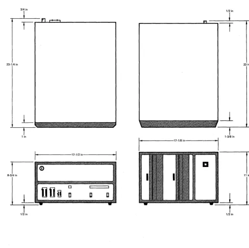
The units should be placed on a convenient flat surface, close 'enough to each other for the interconnecting cables to reach. (Figure 3-3 shows the envelope dimensions of each unit of the UN IVERSAL ONE system.)
Since the CRT terminal and the UN IVERSAL ONE development computer draw cooling air through openings in the bottom of their cabinets, these units should be located where it is unlikely that paper, plastic, carpeting or other materials will be drawn into the air intake and cause overheating. The other units draw cooling air from openings in the rear panel.
3.3.1 Power and Cable Interconnections.
Before connecting any units to the primary power source, turn all power switches to the off position. Rotate the development computer key switch fully counterclock-wise. Ensure that all units are wired for the primary input voltage used. Each system unit has a separate power cord and requires a separate outlet for primary power. Current requirements are as listed in Table 2-1.
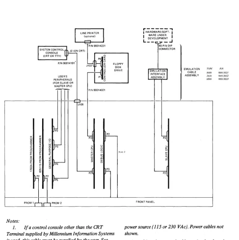
Refer to Figure 3-4 and make the system interconnections as follows:
1. Connect the dual floppy disk unit to the development computer by routing the 40 lead ribbon cable (90014221) from the rear of the disk unit through the center cableway on the rear of the computer to P3 of the Master CPU card. Ensure that pin 1 of the cable (red stripe) is mated to pin 1 of P3.
Replace the top cover on the computer unit.
2. If a line printer is used, connect the ribbon cable (90014172) from the rear of the floppy dfsk unit to the connector on the rear panel of the printer.
Lock the cable in place.
3/4 in
23-1/4 in
L
t
1 in
System I nstallation and Operation
1/2 in
1-3/8 in
11-_ - - - 1 7 - 1 / 8 i n - - - I ' I
23 in
I
....
- - - 1 7 - 1 1 2 in---<·~IDI
I
(i)8-3/4 in 11 in
o
8
EI
8
-_t
1/2 in 1/2 in
Figure 3-3. Envelope Dimensions of System Units
I
LINE PRINTER (optional),...-,
'-r-' PIN 90014221 SYSTEM CONTROL.~2 (ON CRT)
CONSOLE
(CRT OR TTY) ~
J\o;-(H
~
PIN 90014191'
USER'S PERIPHERALS (FOR SLAVE OR MASTER CPU)
----L-rt,08
I 0
I:::
P1 6
u
PIN 90014021
FLOPPY DISK DRIVE
~2
~
f-~
ir u,.---
.,
I HA:.!'~A~~6SEO:T-I I DEVELOPMENT I
L__ _..J 40-PIN DIP CONNECTOR
f
EMULATIONl INTERFACE ASSEMBL Yl,,{
ir
u
EMULATION TYPt" PIN
CABLE 8080 90013021
ASSEMBL Y 2650 90013022 6800 90013023
a: .vote 3 w w
t;;
~
« :;;;(
~
~2 ~2 h
P2~
lJp5
PROM 1 r""1 r'"l PROM 2
Notes:
1. If a control console other than the CRT Terminal supplied by Millennium Information Systems is used, this cable must be supplied by the user. See Table 3-1 for pin assignments of connector JI08 and P3 on master CPU.
2. All units shown (except emulation interface assembly / are individually connected to primary
>
« ~
y
FRONT PANEl
power source (115 or 230 VAc). Power cables not shown.
3. P2 to front panel cable used only when the optional full display front panel is used on the develop, ment computer.
· System I nstallation and Operation
NOTE
If the operator's control console used is a user supplied device (instead of the CRT terminal from Millennium I nformation Systems), the user must also supply the interconnecting cable. See Note in Figure 3-4 for J108 interfacing information.
4. If multiple disk units are included in the system, refer to the special instruc-tions packed with the system for installation of the additional units.
5. Connect all power cords to the line power source.
3.3.2 Controls and Indicators.
The operator controls and indicators on the system units, including peripherals, are described below.
3.3.3 Development Computer.
Referring to Figure 3-5, the following controls are located on the computer front panel:
1. The key-operated switch controls primary power to the unit. When the key is rotated fully clockwise, power is applied; when the key is rotated fully counterclockwise, power is off and the key may be removed.
2. The backlighted display has the following legends:
PWR lights when primary power is applied. MSTR I ights when the master CPU has control. SLV I ights when the slave CPU has control. RUN lights when the system is running.
3. The DIAG I NT switch initiates a reload of UDOS when the system is in the run state. Control is returned to the master CPU. This switch is used with the maintenance diagnostic software.
4. The RESET switch terminates any program in progress. The hardware is initialized, and the operating system is reloaded.
5. The PRO~ POWER switch enables or disables PROM programming power at the front panel PROM sockets. When enabled, the PPWR indicator above the switch is lighted. PROM PWR should be off whenever devices are inserted or rmeoved from the sockets.
6. PROM PROGRAM sockets. The left most socket (PROM 1) is used for programming type 1702A MaS PROMs. The center socket (PROM 2) is used for programming type 82S115 bipolar PROMs. The rightmost socket (PROM 3) is reserved for future use. All three sockets are zero insertion force sockets.
Referring to Figure 3-6, the following items are located on the rear panel.
4) Insert the system diskette into drive O. The correct method for inserting a diskette is shown in Figure 3-8. Ensure that the label side is toward the POWER switch and that the label is the last part of the diskette inserted into the drive. Close disk drive door.
5) Apply power to the line printer.
6) Apply power to the development computer. This will cause an automatic read from drive 0, which will load UDOS into master memory. When UODS has been loaded, a welcoming message will be displayed on the terminal:
>
unos
VER 1.0 TYPE
Where TYPE will be type of slave CPU enabled, such as 8080, 6800,2650, etc., and the> is the UDOS prompt character which informs the user that
UDOS is ready to accept commands.
7) If the welcoming message does not appear within 15 seconds, depress the RESET switch. If the system again does not respond correctly, an improper diskette or a faulty drive may be the problem. Try again with a new system diskette and/or using drive 1. If trouble presists, request service assistance from Millennium.
NOTE
The computer will automatically switch the initializa-tion process to drive 1 if only drive 1 contains a diskette.
8) If the welcoming message is incorrect, the baud rate-setting of the CRT may not correspond to the rate selected on the Master CPU card. Select the correct baud rate on the CRT terminal rear panel. Refer to the UNIVERSAL ONE System Reference Manual for information on changing the baud rate on the Master CPU card.
3.4.3 Manual Reset.
P2 J108 PIN PIN
1 1 2 14 3 2 4 15 5 3 6 16 7 4 8 17
9 5 10 18
11 6 12 19 13 7 14 20
15 8 16 21 17 9 18 22 19 10 20 23 21 11 22 24 23 12 24 25
25 13
26
System I nstallation and Operation
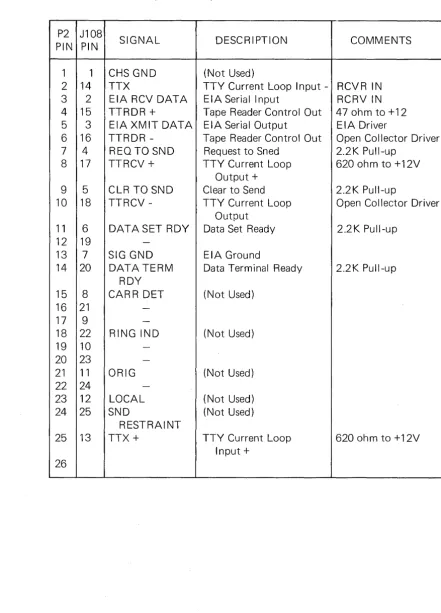
Table 3-1. Pin Assignments of Connectors J 108 and P2. (Development Computer Back Panel and Master CPU)
SIGNAL DESCRIPTION COMMENTS
CHS GND (Not Used)
TTX TTY Current Loop Input - RCVR IN EIA RCV DATA EIA Serial Input RCRVIN TTRDR + Tape Reader Control Out 470hmto+12 EIA XMIT DATA EIA Serial Output EIA Driver
TTRDR - Tape Reader Control Out Open Collector Driver REQ TO SND Request to Sned 2.2 K Pull-up
TTRCV + TTY Current Loop 620 ohm to +12V
Output +
CLR TO SND Clear to Send 2.2K Pull-up
TTRCV - TTY Cu rrent Loop Open Collector Driver Output
DATASET ROY Data Set Ready 2.2K Pull-up
-SIG GND EIA Ground
DATA TERM Data Terminal Ready 2.2K Pull-up ROY
CARR DET (Not Used)
-RING IND (Not Used)
-ORIG (Not Used)
-LOCAL (Not Used)
SND (Not Used)
RESTRAINT
TTX + TTY Current Loop 620 ohm to +12V
Input +
Chapter
4.1 INTRODUCTION.
Universal Disk
Operating System
This chapter describes the Universal Disk Operating System (UDOS) for the UNI-VERSAL ONE system. General topics include the use of the keyboard to enter commands or request control of the system, an overview of the UDOS file structure, a catalog of the UDOS commands and their functions, and a study of the command file capability and overlay areas. In addition, summaries of the UDOS commands and UDOS error messages are provided at the end of the chapter.
4.2 UDOS OVERVIEW.
The Universal Disk Operating System (UDOS) executes in master memory and consists of two sections: resident UDOS which is always present in the master memory, and the UDOS overlays, which are loaded into the master memory auto-matically from the system diskette, whenever certain UDOS commands are invoked. The resident UDOS section, in turn, consists of a PROM portion and a RAM portion.
The PROM resident portion is the UDOS BOOT, which initially loads the resident portion of UDOS from disk into RAM master memory, when the RESET switch is depressed.
The RAM resident portion of UDOS is comprised of the following modules:
• Command Line Processor • SVC Processor
• Job Dispatcher • File Manager • Device Drivers
These modules are described in the following paragraph 4.2.1. In addition, peripheral device I/O buffers are also located in the RAM resident portion.
The EDIT and ASM commands are also a part of the UDOS command set, but because the Editor and Assembler programs both are executed out of the slave memory these commands need not be either resident or in an overlay. Instead, they cause the Command Line Processor to load the corresponding program into the slave memory and need notbe processed further by the UDOS program modules.
4.2.1 Resident UDOS Modules.
The Command Line Processor operates on commands input from the CRT terminal (i.e. the system control console) or from a command file stored in the disk. It in-terprets the command(s), prepares a parameter list, and then causes the function to be performed, by transfering control to the appropriate resident procedure, or by loading and executing an overlay.
The SVC Processor operates on internal requests for I/O or a UDOS service function. All of the I/O communication with system peripherals, for system programs running under the slave CPU, are performed by the SVC Processor.
The Job Dispatcher controls execution of the active jobs in the system. It transfers control to the highest priority job whose I/O operation has been completed, or to the job which, otherwise, is'ready to run.
The floppy disk File Manager and other Device Drivers control operation of the peripheral devices in the system, all of which are interrupt driven.
4.2.2 UDOS Overlays.
The UDOS overlays consist of all UDOS commands except the four memory-resident commands.
Master memory contains two overlay areas into which the UDOS overlay commands are loaded prior to execution. The overlay areas are referred to as overlay area 1 and overlay area 2. Some UDOS overlay commands are executed in overlay area 1, some are executed in overlay area 2, and some occupy both overlay areas during execution.
The UDOS commands are categorized in the following list by the overlay area in which they are executed:
Overlay Area 1 Overlay Area 2 Overlay Area 1 & 2
COpy RHEX ABORT DELETE DSTAT LDIR
DEBUG RSMS ASSIGN DEVICE SET MODULE
DUP VERIFY BKPT DUMP SLAVE
FORMAT WHEX CLBP EXAM SUSPEND
PRINT WSMS CLOSE PATCH TRACE
RPROM WPROM CONT RENAME TYPE
CPROM KILL RESET STATUS
Universal Disk Operating System
UDOS commands can be executed concurrently as long as they do not occupy the same overlay area. I n addition, the concurrent execution must be consistent with the current state of the peri pheral devices and must not cause any system confl icts.
For example, suppose a paper tape was being read into slave memory. This would be accompl ished using the R HEX command (described in paragraph 4.6.6):
:>
F.'While the tape is being processed, file maintenance could be performed. Pressing the ESCAPE key wou Id suspend RHEX execution and display the UDOS prompt character
».
The DE LETE command (paragraph 4.5.1) could then be entered:»DEL FILE1 ... l DATA ... 1 :S:DUPCE ... 1 0
When the0 (RETURN key) was entered, the RHEX command was continued and the DEL command started. Note that RHEX executes in overlay area 1, while DE LETE operates in overlay area 2, which allows the concurrent execution of these progra ms.
4.3 FILES, DEVICES, AND CHANNELS
UDOS is a file-oriented system. The understanding of a file-oriented system is greatly enhanced by understanding the concepts of a file, a device, and a channel.
A file is a set of data. The set has a logical beginning and a logical end. For example, the government's file on a person's tax return might begin with the first return filed by the person and end with the last return fi led. I n between the first return and the last return there could be other returns, audits, etc. All the information beginning with the first return and ending with the last return is the file. In the UN IVERSAL ONE system, files are stored on diskettes. Disk files can be accessed through their logical beginning address, a map that indicates where the data in the file is located on the disk, and a logical ending address.
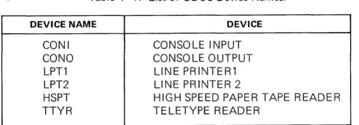
Devices are physical peripherals that provide input and output services for UDOS. The five standard devices are the console input device, the console output device, the line printer, the high speed paper tape reader and the teletype reader. These devices all have reserved names through which the user can access them. These names appear in Table 4-1.
Table 4-1. List of UDOS Device Names.
DEVICE NAME DEVICE
CONI CONSOLE INPUT
eONO CONSOLE OUTPUT
LPT1 LINE PRINTER1
LPT2 LINE PRINTER 2
HSPT HIGH SPEED PAPER TAPE READER
For example, the command:
:>
COP'· .. ' TTYP LPT 1would copy the information from the teletype-paper tape reader to the line printer.
NOTE
Although UDOS software supports a high speed paper tape reader, this peripheral is available only on request.
Files may also be viewed as devices. Fi les can be specified as input or output devices. To refer to a file as a device, the operator must refer to the file name for that file. In addition, if the file is not located on the diskette installed in the system drive, it may be necessary to specify the drive on which the file is located. UDOS can automati-cally create the necessary new fi les or search other diskette directories.
A filename must have the following properties:
1) The filename must contain at least one but not more than eight characters.
2) The characters in the name must come from the following set:
The alphabetic characters (A - Z) The numeric characters (0 - 9)
These special characters: !, ",
#,
%,
&, " (,), *, ;, =, and ? 3) The filename may not begin with a numeric character.4)
The filename must not be one of the reserved names which identify physical devices: CONO, CONI, LPTl, LPT2, HSPT or TTYR.5) The filename must be unique to the diskette containing the file.
Every diskette has a system area, called the directory, where system information is kept on all the files on the diskette. This information includes the filename, disk sectors used, beginning and ending disk addresses, etc. The directory also includes system information which prevents bad disk sectors from being allocated for file usage.
UDOS is only aware of diskettes that are loaded in the available disk drives. For this reason, diskettes are not referred to by diskette name; rather, they are referred to by drive number. As an example, suppose you had diskettes loaded in drives 0 and 1. Drive 0 is the system drive. There is a file named DATA 1 on drive 0 and a file named OAT A 1 on drfve1. If it was necessary to copy the second DATA 1 to the I ine printer, how would this be accomplished? The action is performed by specifying a drive number to indicate which DATA 1 is to be copied. To specify the drive, append the drive number to the file name. This is done by following the filename with a
'I'
to separate the filename and drive and then inserting the drive number. To copy DATA 1 on drive 1 to the line printer, the following command would be performed:Universal Disk Operating System
>
COpy DATA1/1 LPTl
If no drive number is appended to a filename, UDOS normally assumes that the file resides on the system drive, and will search the system drive directory for the fi Ie. See the SEARCH command for an alternative mode.
Channels are used by the program running on the slave CPU. The user can assign a channel to a device using the ASSIGN command. When this is accomplished, the slave is able to perform input or output to the device through the channel. The devices specified in the assignment may be physical devices or files.
4.4 ENTERING UDOS COMMANDS.
When the prompt character> is displayed, the user is allowed to enter commands to UDOS. These commands will all have a similar format. The format is:
> COMMAND PARAMETERS
0
where:COMMAND is the name of the command to be executed;
PARAMETER is all of the required or optional list of parameters for the specified command; and
o
is the RETURN keyThe command is always separated from its parameters by one or more spaces or by a comma.
For example, if the user entered the portion of the following line (after the prompt character) :
>
LDIF.'
00
LDI R would be the command to be executed and 0 would be the parameter for LDI R. When one presses the RETURN key, UDOS is told that a command is waiting to be interpreted. UDOS identifies the command, loads the appropriate program into master memory, and control is passed to the loaded program to perform the requested function. In the LDIR 0 example, the command LDIR, (the List Directory command) is identified by UDOS, and results in the List Directory program being loaded and executed. The parameter, 0, specifies the drive whose directory will be listed. The listing will be displayed on the console.
If one desires a listing that included the system files, the following entry should be made:
where:
LD I R is the command, and
o
and. (which requests that system files be included in the directory listing) are the parameters.Note that a space separates or delimits the two parameters. When two or more para-meters are present in a command I ine, they must be separated by spaces, or by a comma (,). Since the comma is also a delimiting character, the following command line is interpreted by UDOS in the same way as the above example:
>
LDIF.~!'
O!'.0
The space and comma can be used as delimiters in the same command line.
4.5 SPECIAL KEYS.
UDOS pays special attention to certain keys in order to facilitate the entry of command lines and operator control of the system. These keys are DE LETE (or RUBOUT), ESCAPE, and the space bar. UDOS also recognizes CTR L-Z as a special character.
4.5. 1 D~lete Key.
Suppose the operator was entering the command LDIR 0,. discussed in the previous section, miskeyed, and instead entered:
>
LDI<To remove the incorrect character K from the buffer, the DELETE key is used. One depression of the DELETE key deletes the last character in the buffer, and echoes that character to the console. While the console displays:
>
LDKI<the buffer contains LD. The entry of the command I ine can then be completed as if the K was never entered.
Suppose the error in the entry was of this nature:
:> ;
DIP 0and as the operator prepares to enter the delimiting character, notices that ";" was entered instead of L.. Rather than pressing DELETE six times to reach the incorrect character, the operator may delete the entire line through the use of the ESCAPE key.
Universal Disk Operating System
4.5.2 Escape Key.
Pressing the ESCAPE key during entry of a command line can result in different UDOS responses depending on the current system mode. The possible system input modes are:
1) Input is being performed for a UDOS command;
2) Input is being performed for the Editor;
3) Input is being performed for a user application program.
No matter which of these modes the system is operating in, the current input line will be deleted.
If command input for UDOS is being performed, which is the case in the ;DI R 0 example, the system will delete the current command line and then respond with a double prompt
».
An exception to this rule occurs when the EXAM command is being performed. If the ESCAPE key is pressed while EXAM is being performed, the memory locations which were altered prior to the key depression will remain altered.If the Editor is running, the response will be the Editor prompt character (*),
except if the Editor is in the INPUT mode, in which case no prompt character will be displayed.
The system response, when a user application program is running, will depend on what the user has programmed as a response.
The system response to a depression of the ESCAPE key when a UDOS or user pro-gram is executing, as distinguished from console input being performed, is discussed in paragraph 4.6.3, System Control Commands.
4.5.3 Space Bar.
The space bar (key) allows the user to control system output to the console. Suppose the user has completed entering the LDI R
0,.0
command and the system is listing the directory on the console. Depressing the space bar once will temporarily pause output to the console and allow the user to examine the directory before it scrolls off the top of the CRT. Depress the space bar once again and the listing wi II resu me.4.5.4 CTRL-Z Command.
4.6 THE UDOS COMMANDS.
This section provides a description of all UDOS commands with the following exceptions:
*
*
*
*
*
4.6.1
Commands that are primarily used in conjunction with the command file facility are described in paragraph 4.6.8.
Commands that are associated with the Debug function are described in Chapter 5.
The ED IT command is described in Chapter 6.
The ASM command is described in Chapter 7.
Commands that are used for PROM programming and verification are de-scribed in Chapter 8.
The UDOS Command Structure.
All UDOS commands are structured as follows:
I
COMMAND PARAMETERThe command definitions are followed with a description of their function. Most descriptions proceed as follows:
1) The command is presented. Parameters that are optional are enclosed in parentheses. Three periods (. .. ) indicate that the preceding parameter may be repeated as many times as the limitations of the command allow. The minimum characters required to initiate the command are underlined. For example:
I
~y
INPUT ( ... INPUT) OUTPUTCOP INPUT OUTPUT, where INPUT and OUTPUT are two filenames, is the minimum COpy command that will be executed. Additional INPUT files may be specified as in COP INPUT1 INPUT2 INPUT3 OUTPUT.
2) The first sentence provides a brief descri ption of the command's function.
3) The parameters associated with the command are discussed. The effect of parameters on execution and their default values, if any, are described.
4) If further discussion of the command is necessary, the reasoning behind the command, its logic flow, or possible problems are analyzed in the next paragraph.
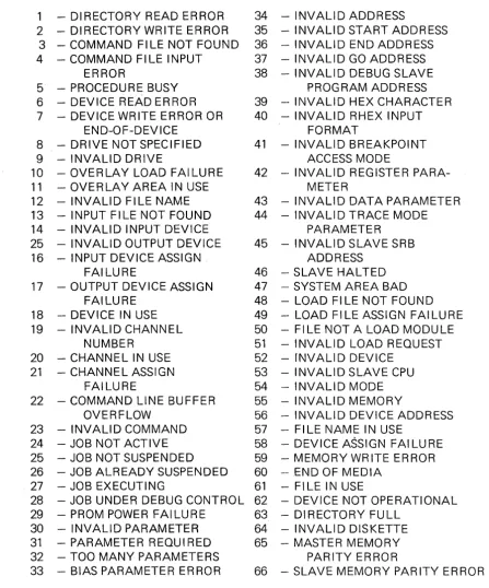
5) The error messages that the command might evoke are listed. The format and a list of UDOS error messages is presented in paragraph 4.6.9 and Table 4-2.
Universal Disk Operating System
In the command line specification, several terms and conventions are used. The terms and conventions involved are NAME, CH, DEVICE, ADDRESS or Ai, FILENAME, 0 and L.
NAME
CH
DEVICE
ADDRESS
refers to a program name. For example, ABORT NAME requests that the program NAME be aborted. If the program VAl L was to be aborted, ABORT VAIL would be used.
refers to a channel number. Channel numbers may be in the range 0 - 7. For example, if channel 2 were to be assigned to the line printer, 2 would replace CH and LPT1 would replace DEVICE in the ASSIGN CH DEVICE command. This would result in ASSIGN 2 LPT1 being executed.
refers to any of the system devices or to any disk files. For example, if channel 3 were to be assigned to the disk file SRCCD/1, 3 would re-place CH and SRCCD/1 would rere-place DEVICE in the ASSIGN CH DEVICE command. This would result in ASSIGN 3 SRCCD/1 being executed.
or Ai refers to a hexadecimal address constant between 0 and FFFF. For example, MODULE FILENAME, A1, A2, A3 could be replaced with MODU LE LDFLE, 100, 2FFF, 80.
FI LENAME refers to a disk file. To edit the file DT A 1/1 using the Editor, the user would issue the command EDIT DTA1/1 where DTA1/1 is a specific instance of the general parameter FI LENAME. Note that in most com-mands it is required that the name of the file be followed by /0, where
o
is the floppy disk drive number.o
refers to the disk drive number. To duplicate the diskette on drive 0 on to the diskette on drive 1, 0 would be used for 01 and 1 would be, used for 02 in the OUP 01 02 command. This would yield a DUP 0 1 command.L refers to a line number. To list the 8th through 14th lines of a file name OTA/1 on the line' printer, the user would replace PR I NT FILENAME ( L 1 L2) wi th P R I NT 0 T A 1/1 8 14.
4.6.2 UDOS Command Completion.
4.6.3 System Control Commands.
The user may control the execution of system or slave programs through these special keys:
ESC
SPACE BAR
The ESC ESC sequence is used to suspend system or slave programs and to return control to UDOS. The space bar key is used to control UDOS displays.
The user may also control the execution of system or slave programs and control the slave channels with these commands:
SUSPEND CaNT ABORT ASSIGN CLOSE
SUSPEND halts program execution. CaNT restarts suspended programs. ABORT terminates program or command execution. ASS IGN forms a connection between a slave channel and a device. CLOSE terminates the logical connection formed by an ASSIGN command.
ESC or
ESC
Space Bar
ESC ESC
A single depression of the ESCAPE key has two possible interpretations:
a) If input was being performed to UDOS, the Editor, or an application program, refer to paragraph 4.5.2 for a discussion of the actions taken.
b) If an UDOS or user program is executing, a single depression of the ESCAPE key will result in that program being temporarily suspended, unless the program is one of the following fou r U DOS programs:
LDIR TRACE STATUS DUMP
If one of these four programs is executing, a depression of the ESCAPE key will terminate its execution. To restart any of the other UDOS programs or the user program after it has been temporarily suspended by ESCAPE, either press RETURN or enter a valid UDOS command.
When the ESCAPE key is depressed, UDOS will respond with a double prompt to record the fact, unless a command line is being input to the Editor or to a user application program.
Two consecutive depressions of the ESCAPE key will result in all active programs in the system being suspended. No program suspended by this double depression of the ESCAPE key will resume execution unless the user issues a CONT (Continue Execution) command.
SPACE BAR
Suspend
Cont
SUSPEND NAME or
SUSPEND-~
or
SUSPEND
I
This command suspends the execution of active programs. The Debug program