OR SUHAIBAH BI TI AZRI
NOR SUHAIBAH BINTI AZRI
A thesis submitted in fulfillment of the requirements for the award of the degree of
Master of Science (Geoinformatics)
Faculty of Geoinformation and Real Estate Universiti Teknologi Malaysia
ACKOWLEDGEMET
In preparing this thesis, I was in contact with many people, researchers, academicians, and practitioners. They have contributed towards my understanding and thoughts. In particular, I wish to express my sincere appreciation to my main thesis supervisor, Professor Dr. Alias Abdul Rahman, for encouragement, guidance, critics and friendship.
I am also indebted to Ministry of Science, Technology & Innovation (MOSTI) for funding me with National Science Fellowship (NSF) scholarship for my MSc study.
ABSTRACT
ABSTRAK
Pelbagai isu dan aspek perlu dikaji dan diberi perhatian ketika evolusi Sistem
Maklumat Geografi dua - dimensi (2D GIS) ke Sistem Maklumat Geografi tiga -
dimensi (3D GIS).Antara isu yang perlu diberikan perhatian ialah permodelan data
spatial 3D, pengurusan data 3D dan analisis 3D. Untuk membentuk objek dalam
persekitaran 3D, kepelbagaian geometri 3D diperlukan dalam sesebuah sistem
pengurusan pangkalan data (DBMS). Sebahagian besar DBMS hanya menyokong
beberapa geometri 3D yang mudah seperti titik 3D, garis 3D, poligon 3D. Bentuk
kompleks dan bentuk yang berisipadu tidak disokong oleh DBMS buat masa ini.
Walaubagaimanapun, di dalam dunia nyata, objek dimodelkan dengan pelbagai
bentuk geometri dan tidak terhad kepada bentuk mudah sahaja. Kurangnya pelbagai
geometri di dalam sesebuah DBMS mungkin akan memberikan batasan kepada
pengguna untuk memodelkan dan menyimpan beberapa objek di dalam pangkalan
data. Oleh itu, penyelidikan ini bertujuan untuk menyiasat dan melaksanakan
beberapa jenis geometri 3D berdasarkan bentuk yang mempunyai isipadu atau
dikenali sebagai objek 3D primitif. Empat jenis objek 3D primitif sahaja yang
digunakan dalam penyelidikan ini dan objek tersebut ialah kon, silinder, sfera dan
torus. Prosidur baru untuk membentuk setiap bentuk diselidiki dan dilaksanakan
dalam pangkalan data. Setiap prosedur yang dibangunkan diuji dengan menggunakan
set data simulasi serta set data sebenar. Objek yang dibentuk seharusnya dapat
memberikan pengguna beberapa maklumat dengan menggunakan pertanyaan mudah
terhadap jadual objek. Kerja penyelidikan boleh diperluaskan lagi di masa depan
TABLE OF COTETS
CHAPTER TITLE PAGE
DECLARATIO ii
DECLARATIO iii
DEDICATIO iv
ACKOWLEDGEMETS v
ABSTRACT vi
ABSTRAK vii
TABLE OF COTETS viii
LIST OF TABLES xii
LIST OF FIGURES xiii
LIST OF ABBREVIATIOS xvii
LIST OF SYMBOLS xviii
1 ITRODUCTIO 1.1 Introduction 1
1.2 Background to The Problem 3
1.3 The Problem Statement 8
1.4 The Aim 9
1.5 The Objectives 9
1.6 The Scope 9
1.6.1 The Objects 10
1.6.2 The Datasets 11
1.6.3 The Hardware and Software 11
1.8 Research Workflow 15
1.9 The Thesis Structure 16
1.10 Conclusions 17
2 3D PRIMITIVE OBJECTS AD SPATIAL DBMS 2.1 Background 18
2.2 Primitive Objects 19
2.2.1 Sphere 20
2.2.1.1 Spherical Coordinates 21
2.2.2 Cylinder 24
2.2.3 Cone 26
2.2.4 Torus 28
2.3 Solid Modeling 31
2.3.1 Decompositions Model 33
2.3.2 Constructive Solid Geometry (CSG) 36
2.3.3 Boundary Representation 37
2.4 Polyhedron 40
2.5 Polygon Orientation 42
2.6 Spatial Database Management System 44
2.6.1 Geometry and Dimension in Spatial DBMS 45
2.6.2 Volumetric Object in Spatial DBMS 46
2.7 Oracle Spatial DBMS 47
2.7.1 Supported Geometry Types 49
2.7.2 SDO_Geometry 51
2.7.3 Interoperability 54
2.8 Summary 55
3 MODELIG 3D PRIMITIVE OBJECTS 3.1 Background 56
3.2 Modeling Objects using B-Rep and Spherical Coordinates 57
3.3 Constructing 3D Primitive Objects 58
3.3.1 Sphere 58
3.3.3 Cylinder 68
3.3.4 Modeling Cylinder 70
3.3.5 Cone 72
3.3.6 Modeling Cone 74
3.3.7 Torus 76
3.3.8 Modeling Torus 78
3.4 Conclusion 81
4 THE IMPLEMETIO OF 3D PRIMITIVE OBJECTS AT DBMS LEVEL 4.1 Background 83
4.2 Implementation Approach 84
4.2.1 Stored Procedure 84
4.2.2 Create Procedure 86
4.2.3 Load Procedure in DBMS 90
4.3 3D Primitive Objects in DBMS 91
4.3.1 Indexing of Spatial Data 93
4.3.2 Creating Spatial Index and Spatial Index Parameter 95
4.3.3 3D Primitive Objects Procedure 98
4.3.4 Volume and Area Calculation 100
4.4 Rotation Element 110
4.5 Conclusion 117
5 RESULTS AD QUERY 5.1 Background 118
5.2 Visualization of 3D Primitive Objects 119
5.3 3D Primitive Objects in DBMS 119
5.3.1 Cone 121
5.3.2 Cylinder 123
5.3.3 Torus 125
5.3.4 Sphere 128
5.3.5 Half Cone 130
5.3.7 Half Torus 132
5.3.8 Quarter Torus 134
5.3.9 Hemisphere (Half Sphere) 135
5.4 Rotation Element 136
5.5 Combination of 3D Primitive Objects 145
5.6 3D Primitive Objects and Real Datasets 151
5.7 Query 155
5.8 Surface Smoothness 157
5.9 Conclusion 159
6 COCLUSIO AD RECOMMEDATIO 6.1 Conclusion 160
6.2 Recommendation 164
REFERECES 166
Appendices A-C 173-189
LIST OF TABLES
TABLE O. TITLE PAGE
2.1 Supported geometry types in Geo-DBMS 42
2.2 Valid SDO_GTYPE values Oracle (2007) 52
4.1 DBMSs and supported programming language for stored
procedure (Wikipedia, 2010) 85
4.2 Parameters of 3D primitive objects 93
4.3 Rotation Matrix 111
LIST OF FIGURES
FIGURE O. TITLE PAGE
1.1 A procedure to store cube in Oracle DBMS 5
1.2 Missing procedure in DBMS 6
1.3 Polyhedron to construct a cylinder 7
1.4 Missing Objects in DBMS level 12
1.5 Basics syntax for the CREATE OR REPLACE PROCEDURE statement 13 2.1 Several 3D primitive objects 19
2.2 Extended 3D primitives objects 20
2.3 Structure of sphere 20
2.4 Spherical Coordinates 21 2.5 Location of point P by spherical coordinates (r, θ, φ) and rectangular coordinates (x, y, z) 23 2.6 Sphere with center (xo,yo,zo) and radius R 23 2.7 Points on sphere with radius r 24 2.8 Structure of cylinder 25 2.9 Right Cone 27
2.10 Simple Torus 28 2.11 Structure of Torus 29 2.12 Location of variable c and a in equation 2.29, 2.30 and 2.31 30 2.13 Location of variable u and v in equation 2.29, 2.30 and 2.31 31 2.14 Location u and v in torus structure with x, y and z plane 31 2.15 Exhaustive Enumerations 34
2.16 Quad tree models 35
method
2.18 Modeling cube using Boundary Representation method 38
2.19 Baumgart’s winged-edge data structure 38
2.20 Right Hand Thumb Rules 43
2.21 Polygon drawn counter-clockwise 43
2.22 Direction of normal surface 44
2.23 Oracle Spatial Components 48
2.24 Geometry type in Oracle 11g 50
2.25 Conceptual class diagram of the SDO_GEOMETRY data type 54 3.1 Location of φ , θ and r on the x,y,z plane 58 3.2 Radius r from centre point of sphere 59
3.3 Polyhedron on the sphere surface (up and bottom) 60
3.4 The degree of round circle is 360° 61
3.5 Divided sector angle is θ = 18° 61
3.6 New points generated along the latitude 62
3.7 Divided sphere diameter 62
3.8 New latitude with its centre point xn, yn, zn 64
3.9 Ten generated latitudes with the origin latitudes 64 3.10 Right triangle is formed after joining all the three points 65 3.11 Triangle in Theorem Pythagoras definition 66
3.12 The right triangle 66 3.13 Complete generated points along the latitudes 67
3.14 Generating Polyhedron from points to model Sphere 68
3.15 Cylinder with height h and radius r 68
3.16 Top and bottom surface of cylinder 69 3.17 Body of cylinder 69 3.18 Location of φ, θ and r. 70 3.19 Generated points at the bottom surface of cylinder 71
3.20 Generated centre points for the top and bottom surface of cylinder 71 3.21 Generated Polyhedron from points to model Cylinder 72
3.23 Collection of face to construct the body and base of cone 73
3.24 Location of φ, θ and r for the circular base of cone 74 3.25 Generated point along the cone base 75
3.26 Generated cone from several points 76
3.27 Torus with the main radius of Rmain and subradius of rtube. 76 3.28 Types of Torus 77
3.29 Constructed torus from rectangle 78
3.30 Collection of polygon faces to construct torus 78
3.31 Circle base geometry for torus 79
3.32 Illustrate the generated points on torus surface based on the centre point and radius R 80 3.33 Generated points using sub radius r along tube cross section 80 3.34 Polyhedron to construct torus 81
4.1 PL/SQL in Oracle database server Oracle, 2007 86
4.2 The basic syntax for the CREATE OR REPLACE PROCEDURE statement 88 4.3 Procedure is created in DBMS 90
4.4 MBR enclosing the geometry 94
4.5 Example of R-Tree index for a set of points 94
4.6 Storage of R-Tree spatial indexes 95
4.7 Area and volume value for cone 103
4.8 Area and volume value for cylinder 106
4.9 Area and volume value for torus 108
4.10 Area and volume value for sphere 110
4.11 Rotation on the axis x, y and z 111 4.12 The left-handed orientation is shown on the left, and the right-handed on the right. 112 5.1 Data interoperability through Oracle and Bentley 119
5.2 Retrieved cone datasets through CAD viewer 122
5.3 The Geometry of Cylinder in Bentley Map 125
5.4 Retrieved Geometry of Torus in Bentley Map 127
5.6 Visualization of half cone from different views 131
5.7 Visualization of half cylinder from different views 132
5.8 Visualization of half torus from different views 133
5.9 Visualization of quarter torus from different views 134
5.10 Visualization of hemisphere from different views 135
5.11 Rotation of cone towards the axis –xRx(θ) = 90° (right) 136
5.12 Rotation of cone towards the axis –yRy(θ) = 90° 137
5.13 Rotation of cone towards the axis –zRz(θ) = 90° 138
5.14 Rotation of cylinder for axis –xRx(θ) = 90° 139
5.15 Rotation of cylinder for axis –yRy(θ) = 90° 139
5.16 Rotation of cylinder for axis –zRz(θ) = 90°. 140
5.17 Rotation of torus for axis –xRx(θ) = 90° 141
5.18 Rotation of torus for axis –yRy(θ) = 90° 142
5.19 Rotation of torus for axis –zRz(θ) = 90° 142
5.20 Rotation of sphere for axis –xRx(θ) = 90° 143
5.21 Rotation of sphere for axis –yRy(θ) = 90° 144
5.22 Rotation of sphere for axis –zRz(θ) = 90° 144
5.23 Simulation of tower structure 147
5.24 SALT building structure SAOO (2010). 148
5.25 Simulation of SALT building 149
5.26 Simulation of pipeline in various directions 150
5.27 Real datasets of building tower in Suleymaniye area 151
5.28 The real image (left) and the constructed tower using 3D primitive objects with cube and faces (right) 153 5.29 Image of the experimented object 154
LIST OF ABBREVIATIOS
2D - Two-dimensional
2.5D - Two-and-a-half-dimensional
3D - Three-dimensional
CAD - Computer Aided Design
GIS - Geography Information System
DBMS - Database Management System
SQL - Structured Query Language
CSG - Constructive Solid Geometry
B-Rep - Boundary Representation
LIST OF SYMBOLS
A - area
Asphere - surface area of sphere
Acylinder - surface area of cylinder
Acone - surface area of cone
Atorus - surface area of torus
Awithout top or bottom - surface area without the top or bottom
Awith top or bottom - surface area with the top or bottom
Tcylinder - total surface area of cylinder
π
- pi = 3.142r - radius
Rmain - radius from the center of the hole to the
center of the torus tube
Rtube - radius of the tube
V - volume
Vsphere - volume of sphere
Vcylinder - volume of cylinder
Vcone - volume of cone
Vtorus - volume of torus
θ - angle
φ
- azimuthh - height
s - cone side/slant height
c - c is the radius from the center of the hole to the center of the
torus tube
a - a is the radius of the tube
u - angle of torus longitude
v - angle of torus latitude
CHAPTER 1
ITRODUCTIO
1.1 Introduction
visualization and information of the spatial objects and leads to incorrect understanding and information.
Due to the restrictions of 2D GIS, users have begun using 3D GIS. 3D GIS can offer a better understanding and provide better information to users. With regards to this issue, several researches on 3D GIS have been done in the past few years. Zlatanova et. al (2002), Stoter et. al (2005), and Abdul Rahman et. al (2002) have discussed and done some research on 3D GIS concerning various issues such as 3D object visualization, editing, modeling and future direction. With these attempts, the existence of 3D GIS can be seen today in many applications, systems and software. For example, an attempt to realizing a 3D format and tool based on XML format. This 3D XML-based format known as CityGML, which is an open data model for storage and exchange of virtual city models. CityGML is a common information model for the representation of 3D urban objects, and was developed by a group of researchers in Germany (SIG 3D) in 2002. Mainstream GIS software such as ArcGIS (ESRI), PAMAP GIS Topographer (PCIGeomatics) and Geomedia Terrain (Intergraph) are also embedded with 3D elements, tools or functions. These 3D elements in GIS software have been discussed by Zlatanova et. al (2002). Given the effect of various attempts and approaches, 3D GIS has today emerged as a trend to provide information in various fields and applications.
spatial and semantic attributes. In addition, the Open Geospatial Consortium (OGC) created the Simple Features specification and set the standards for adding spatial functionality to database systems. Standards on a manner of representing, accessing and disseminating spatial information in a central DBMS were set by OGC as a benchmark for DBMS vendors in developing spatial DBMS. Thus, DBMS vendors such as Oracle, PostGIS and Ingres have developed spatial DBMS based on traditional DBMS. As a result, the current spatial DBMSs are able to maintain spatial data types such as point, linestring and polygon.
As mentioned before, the current spatial DBMSs are capable of handling several geometry types such as point, linestring and polygon. These geometry types were successfully implemented in DBMS level. Moving towards 3D GIS means that 3D data have to be managed in DBMS level. Furthermore, 2D geometry type in DBMS level is almost complete while in contrast, 3D geometry type is not completely implemented at DBMS level. There are still other 3D geometry types that need to be implemented, such as volumetric geometry type. Thus, this research focuses on how to construct several missing geometry types based on volumetric shapes at DBMS level.
1.2 Background to the Problem
line and polygon while Ingres supports the additional type of a circle besides the three basic types. Unlike Informix and Ingres, Oracle DBMS supports more than three basic types. The supported types are line, point, polygon, circle, arc strings and compound polygon.
GIS and Computer Aided Design (CAD) are two different systems and both are designed for different purposes. The CAD system is designed for modeling and visualizing 3D objects and provides designing tools in many applications such as modeling, construction and industrial parts. Since CAD is developed for designing objects, a lot of emphasises was given to editing tools and 3D visualization without maintenance of attributes and coordinate system as stated by Zlatanova (2004). Meanwhile, GIS provides the integration of semantic, geometric data and spatial relationship; according to Stoter et. al (2003), this makes GIS the most appropriate system for serving spatial applications. Typically, GIS supports only a limited number of geometry types such as point, line and polygon while CAD system supports more complex geometry such as sphere, cone, nurbs and etc. However, all these complex geometries in CAD cannot be manipulated and are quite unmanageable for proper GIS purposes.
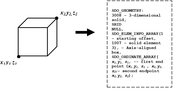
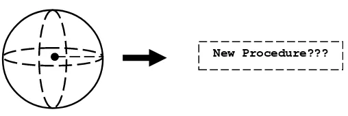
As mentioned in the preceding section, most of mainstream DBMSs support basic simple geometry type. Due to the increasing requirement for representing, accessing and disseminating data from CAD and GIS field, Zlatanova et. al. (2002) suggested that DBMS should give more support to spatial data type and its operations especially in 3D environment. There has been an attempt to provide a 3D environment in DBMS level by supporting 3D points, 3D lines and 3D face and recently a solid cube, by Oracle (2007). Although all these geometry data types have been successfully implemented in DBMS level, other geometry types especially those based on volumetric objects are still missing. Figure 1.1 shows the supported geometry of cube and its procedure in DBMS and Figure 1.2 shows a volumetric based object i.e. sphere which is still a problem for spatial DBMS. Thus the construction of volumetric objects such as sphere, cone and other shapes are investigated thoroughly in this research.
Figure 1.1: A Procedure to store cube in Oracle DBMS. SDO_GEOMETRY: 3008 – 3-dimensional solid,
SRID NULL,
SDO_ELEM_INFO_ARRAY(1 – starting offset, 1007 – solid element 3), – Axis-aligned box,
SDO_ORDINATE_ARRAY( x1,y1, z1, -- first end point (x1,y1, z1 , x2,y2, z2)– second endpoint x2,y2, z2);
x2,y2, z2
x1,y1, z1
•
Figure 1.2: Missing procedure in DBMS.
A few researches on implementing 3D objects at DBMS level have already been investigated by a few researchers. The first attempt of 3D spatial data type and corresponding operations in a spatial DBMS was investigated by Arens (2003) and Arens et. al (2005), and later extended by Chen (2008). The basic idea of these researches is that a 3D polyhedron can be defined as a bounded subset of 3D space enclosed by finite set of flat polygons; hence every edge of a polygon is shared exactly by one another. Here, the polygons are in 3D space because they are represented by vertices, which can be 3D points in a spatial DBMS.
Another research related to 3D objects is the modeling of freeform curves and surfaces by Pu (2005). In his research, Pu (2005) attempted to manage freeform curves and surfaces in spatial DBMS. In the real world, objects are freeform and not limited only to points, lines and polygons. Objects such as roads, territory surfaces and earth surfaces need freeform geometry types or shapes to model it. Freeform shapes can be simulated by tiny line segments/triangles/polygons but this is quite unrealistic and inefficient, especially for complex surfaces and huge areas. Therefore, Zlatanova et. al (2006) introduced a mechanism or procedure to store freeform shapes directly in DBMS. With this effort, the possibility of developing a new 3D data types in DBMS has been made obvious.
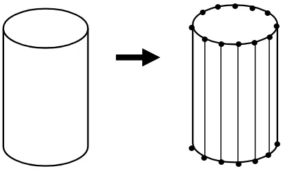
In the preceding section, all of the researches were capable of proving the possibility of implementing more 3D geometry data types. One of the ways to store 3D object in DBMS is by a bounded sets of multipolygon or triangle on the objects surface, as shown by Arens (2003) and Arens et. al (2005) whereby by using this mechanism, coordinates on each faces would be defined manually. The problem with this mechanism is that it may be quite inefficient and time consuming to define points on the object surface, especially when one is dealing with complex objects with a huge surface. Thus a better and reliable method is needed to generate 3D objects, especially for volume based objects such as sphere, cylinder and others in DBMS level. Figure 1.3 shows an example of constructing a body of cylinder using polyhedron method. By inserting the coordinate manually, one has to define the coordinate for all faces to generate a cylindrical body. From the figures, it is clearly shown a large set of coordinates is required to generate that 3D object by using polyhedron method.
Figure 1.3: Polyhedron to construct a cylinder.
As mentioned before, Arens (2003) had done some research on modeling 3D objects using the polyhedron method. Chen et. al (2008) extended this research by investigating a suitable way of developing a new 3D data type, polyhedron, for both geometrical and topological data types and spatial operations. By using this approach, more 3D objects or solid volumetric objects can be investigated such as Cone, Cylinder, Sphere and Torus. It is therefore possible to model objects using a certain modeling technique and construct them in DBMS with new procedure.
Based on the discussion above, it can be seen that there is a possibility of creating and implementing more 3D objects, especially 3D primitive objects, in DBMS level. This research focuses on how to model and construct 3D primitive objects, then implement the constructed objects in DBMS.
1.3 The Problem Statement
1.4 The Aim
The aim of this research is to investigate new 3D objects representation based on sphere, cone, cylinder and torus, and incorporate all these objects with spatial DBMS. Queries are performed from the developed database.
1.5 The Objectives
In this research, there are three objectives to be achieved and completed. The objectives are:
1. To design 3D primitives based on sphere, cone, cylinder and torus for geospatial DBMS.
2. To develop a database for the 3D objects.
3. To test the object by using real dataset and simulation dataset and perform queries from the developed database.
1.6 The Scope
1.6.1. The Objects
In this experiment, only four primitive objects are used to be implemented in DBMS level. The objects are Cone, Cylinder, Sphere and Torus. Each object is constructed with suggested minimum number of points on the object to get the exact shapes of the object. Every object may have different minimum number of points. The numbers of points on each object are:
i. Sphere
Minimum number of points along the latitude of sphere is determined to 20 points. 10 latitudes plus the origin latitudes are used to construct a sphere. Thus minimum numbers of points are 220 points.
ii. Cylinder
On the top and bottom of the cylinder, 20 minimum numbers of points is generated along the circular based. Total minimum numbers of points to construct a cylinder are 40 points.
iii. Cone
Along the circular base of cone 20 points is defined and 1 point is defined on the top of the cone. Thus the total numbers of minimum points on the cone surface are 21 points.
iv. Torus
parts for 10 points. Total minimum number of points on the torus surface is 200 points.
1.6.2. The Datasets
In this experiment, two type of data set are used. The datasets are:
i. Real datasets
In this research, the datasets are derived from architecture drawings in CAD within Suleymaniye area, Istanbul, Turkey. Only certain parts of the building are modeled using 3D primitive objects in this experiment, which are the parts based on sphere, cylinder, cone and torus forms.
ii. Simulation datasets
3D primitive objects are tested using simulation datasets.
1.6.3. The Software and Hardware
The software and hardware for this research are:
• Oracle Spatial 11g R2 as a DBMS to store spatial datasets
• Bentley Map as a spatial viewer
• PL/SQL language as a platform to compile new procedure in DBMS
1.7 Brief Methodology
There are five phases of methodology in this research. Each phase is explained in the following paragraph:
Phase 1: Object Modeling
i. In this phase, several 3D primitive objects are identified. The objects are:
(a) Sphere (b) Cylinder (c) Torus (d) Cone
Figure 1.4 shows several identified object are missing in DBMS level.
Figure 1.4 Missing Objects in DBMS level.
ii. Every object’s formula is identified
iii. A suitable technique to model the objects is investigated
Phase 2: Create a Procedure for 3D Primitive Objects and Load the procedure in DBMS.
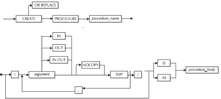
In this experiment, a function called stored procedure in DBMS is used as a platform to create and launch object’s procedure. Possible compilers such as Java and PL/SQL are used as a compiler to develop the procedure. The procedures are then loaded in DBMS. The following railroad diagram in Figure 1.5 illustrates the basic syntax for the CREATE OR REPLACE PROCEDURE statement using PL/SQL
language in stored procedure:
Figure 1.5: Basics syntax for theCREATE OR REPLACE PROCEDUREstatement
(Urman et. al. 2004)
After creating the procedure, it is loaded in the database. Procedure is loaded only for the first time. After that, CALL statement is used to call the procedure.
Phase 3: Create a Database for 3D Primitive Objects and Call Created
Procedure
The table is designed based on the constructed objects in Phase 3, after which each created table must be indexed as a prerequisite for the created procedure to be ready for execution. Each table must be indexed with spatial indexes to speed up query on the tables. Spatial index is considered as a logical index. Several issues that should be considered in this phase are updating the user sdo geometry metadata and the index parameter.
Phase 4: Integrating DBMS and CAD Viewer
CAD viewer is a suitable viewer for visualizing objects from DBMS. There are several CAD applications capable of visualizing and modeling objects from DBMS such as Bentley and Autodesk. In this research, Bentley Map is used as a viewer. To integrate Oracle DBMS and CAD viewer, interoperability function is used to connect both of this system.
Phase 5: Test and Query from the Developed Database
i. Result is viewed using CAD viewer in order to test stored datasets in DBMS.
1.8 Research Workflow
Compile the objects
LOAD Create Procedure
Procedure
Query Possible Volumetric Objects
Query the developed database
Create Table
• Update Metadata
• Indexed
Execute Procedure
Retrieve data using CAD Viewer
1.9 The Thesis Structure
Chapter 1 starts with the introduction of 3D GIS and issues related to spatial DBMS. This chapter also includes the background on the research aspects such as background of the problem, the problem statement, the objectives, the aims, the scopes, the methodology, summary of methodology and the thesis structure.
Chapter 2 discusses and reviews some related literature. The related literature includes objects modeling, 3D primitive objects, spatial DBMS and its issue. From the reviewed literature, a method to construct 3D primitive objects is also discussed.
Chapter 3 explains how to construct and model 3D primitive objects based on the reviewed literature. This chapter also highlights the conceptual model of 3D primitive objects.
Chapter 4 is regarding the implementation of constructed 3D primitive objects in DBMS. The main process in this chapter is on how to structure data and map the conceptual model in DBMS.
Chapter 5 discusses the test or experiment towards implemented objects in DBMS. The query is performed and the results are discussed in this chapter.
1.10 Conclusion