Robot Path Generation Method for a Welding System
Based on Pseudo Stereo Visual Servo Control
Theodore P. Pachidis
Department of Electrical and Computer Engineering, Democritus University of Thrace, Xanthi 67100, Greece Email:[email protected]
Kostas N. Tarchanidis
Department of Petroleum Technology, Technological Educational Institute of Kavala, Ag Loukas, Kavala 65404, Greece Email:[email protected]
John N. Lygouras
Department of Electrical and Computer Engineering, Democritus University of Thrace, Xanthi 67100, Greece Email:[email protected]
Philippos G. Tsalides
Department of Electrical and Computer Engineering, Democritus University of Thrace, Xanthi 67100, Greece Email:[email protected]
Received 30 December 2003; Revised 18 August 2004
A path generation method for robot-based welding systems is proposed. The method that is a modification of the method “teach-ing by show“teach-ing” is supported by the recently developed pseudo stereovision system (PSVS). A path is generated by means of the target-object (TOB), PSVS, and the pseudo stereo visual servo control scheme proposed. A part of the new software applica-tion, called humanPT, permits the communication of a user with the robotic system. Here, PSVS, the robotic system, the TOB, the estimation of robot poses by means of the TOB, and the control and recording algorithm are described. Some new concepts concerning segmentation and point correspondence are applied as a complex image is processed. A method for calibrating the endpoint of TOB is also explained. Experimental results demonstrate the effectiveness of the proposed system.
Keywords and phrases:path generation, pseudo stereovision system, robotic application HumanPT, target-object, calibration, complex image.
1. INTRODUCTION
A robotic manipulator could be used in an arc-welding sys-tem. In a system like this many problems may be encoun-tered. Some of them are (1) the movement accuracy of a torch mounted on the end effector of the robotic manipu-lator, (2) the generation of a proper path the torch must fol-low, (3) the flexibility of the system to adapt the specified path to any changes in the shape of the metal pieces to be welded, (4) the possibility of the system to change the move-ment rate, or the pattern of movemove-ment relatively to metal types or welding surfaces shape. The method “teaching by showing,” as a method for path or trajectory generation by
This is an open access article distributed under the Creative Commons Attribution License, which permits unrestricted use, distribution, and reproduction in any medium, provided the original work is properly cited.
means of a vision system, mainly assumes that a user moves the under manipulation object with his/her hand. The vision system captures images of successive scenes of the object as it is moved and then, using these images, calculates the desired path or trajectory. The different versions of this method are not easily applicable in cases where a new trajectory might be generated for a robot-based arc-welding system.
paradigm. The user specifies the desired trajectory by mov-ing the object to be manipulated with his/her hand. The performance was measured with a stereovision system. In [6] Kang presented a system that observes a human per-forming the task recognizes the human grasp, and maps it onto the manipulator. In [7], Brunner et al. proposed the so-called telesensor programming concept as an easy way to program a robot off-line via learning by showing in a virtual environment. Voyles and Khosla in [8] proposed a gesture-based programming method of a robot. In [9], Johnson and Marsh presented the basic mathematical and computational framework for a new method of modeling robot manipulator workspaces. In his Ph.D. thesis [10], Sabes studied the plan-ning of visually guided arm movements in two cases: feed-back perturbation and obstacle avoidance. In [11], Gu stud-ied the visual guidance of a robot by means of a stereovision system and using as features corner points. P¨aschke and Pauli in [12] implemented the programming-by-demonstration method to reconstruct a smooth 3D trajectory of a grip-per, using a stereovision system. Sharma and Sutanto [13] presented a planning framework by using motion-planning techniques that take into account properties of sensed data (visual feedback). Berry et al. [14] described an approach to the problem of trajectory generation by visual servoing. In [15], Ruf and Horaud proposed a methodolog-ical framework for trajectory generation in projective space. Kim et al. [16] presented a method for automatic teaching of a welding robot for free-formed seam by means of CAD data and data acquired by a laser vision sensor. In their paper [17], Zha and Du presented a new approach to the generation and optimization of the position and orientation trajectories in Cartesian task space. Simulation was made in a virtual CAD-based off-line programming environment. In their recent pa-per Mezouar and Chaumette [18] considered a single-camera vision system mounted on a robotic manipulator. The model of the target-object is known. The camera keeps the object in the field of view and a trajectory is generated as this vision system is moving from an initial location to a final location. They examine also the case in which the object model is un-known. Finally, in their paper [19], Pachidis et al. proposed a system for path generation by means of a novel stereovi-sion system (called pseudo stereovistereovi-sion system, PSVS) and complex images, which are captured from static scenes of the robot environment.
Many researchers presented also papers concerning vi-sual servo control. Most of the vivi-sual servo control tech-niques are based on monocular vision systems [20,21,22, 23,24,25,26,27,28,29] and some of them are based on stereovision systems or multicamera vision systems [30,31,
32,33,34,35].
The proposed system is a pose-based, endpoint closed loop (ECL), stereo visual servo control system (SVSCS) [36], in which the different locations of a moving special con-structed object are recorded by means of PSVS. This dif-ferent control system is called pseudo SVSCS because for first time PSVS is included in the control scheme. It uses as a target-object (TOB) a set of three planar light sources on the vertices of a triangle attached to an aluminum bar.
These three sources belong to a 5×7 dot matrix display. Their planarity has as a result the homogeneous projections to the complex image plane. Thus, as it normally happens with simple LEDs [14,28], problems of diffusion or other phenomena of the projected areas do not exist. A pseudo stereovision system (PSVS) [37] is mounted on the end ef-fector of the manipulator. An ordinary stereo system could be also used. PSVS keeps always the motion by an operator TOB in the field of view. At the same time, a predefined vir-tual point, with respect to the camera frame, tracks a point on the TOB (center of gravity) as it moves. In other papers, that is, [38], the end effector follows a path to track a sta-tionary desired point or tracks it. Moreover, the current state of the TOB is calculated and recorded by the system as a state vector with respect to the world coordinate system, es-tablished on the base of the robotic manipulator Puma 761. The operator drives the TOB along a virtual or real desired path. This is possible by means of the special constructed metal drivers; the operator can drive the TOB along a de-sired path, that is, a straight line, with prespecified angles that depend on the type of the metal driver. The generated path can be the path of a simple task, a part of a procedure, or the path the torch of a robot-based welding system follows. While PSVS keeps the TOB in the field of vision, in system loop cycle, state vectors can be calculated and recorded with sampling rates equal to or lower than the system loop cy-cle. The sampling rate is determined by means of the graph-ical user software interface (GUI), part of the recently devel-oped robotic application calledHumanPT. It is a complete robotic application developed in visual C++. Its architecture is presented for the first time and can be implemented in personal computers (without the need of special hardware), permitting its use in more friendly environments. The op-erating system used is Microsoft Windows. Some other ad-vantages of the proposed system are (1) easy segmentation of the three light sources image, (2) subpixel measurement ac-curacy, (3) robust stereo matching, (4) path generation in the working space of a robotic manipulator, and (5) model-free method.
In the sections below, PSVS is described in brief. The vi-sual servo control scheme as well as the TOB and the calcula-tion of state vectors are presented and analyzed. Experimen-tal results indicate the effectiveness of the system to gener-ate robot paths by means of the proposed pose-based pseudo stereo visual servo control method. The paper is organized as follows. InSection 2, PSVS and the related equations are briefly described. InSection 3the robot system structure and HumanPTarchitecture are provided. InSection 4, details for the TOB are given and the theory related with the calculation of state vectors is provided. InSection 5, the visual servo con-trol method is presented. Experimental results are depicted
in Section 6. Finally, conclusions of this work are given in
Section 7.
2. PSVS DESCRIPTION AND CALIBRATION
x
z
1 2
3
4
m
45◦
θr
θi
d a
O a
Real camera
O1 Virtual camera 1
O2
l
Virtual camera 2
ω1
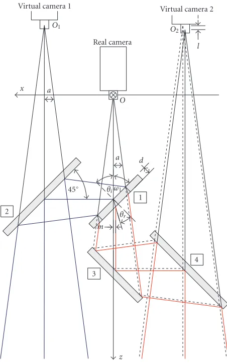
Figure1: A pseudo stereovision system (PSVS) is presented. Real and virtual cameras as well as the camera coordinate system are il-lustrated.
stereovision system with two parallel cameras could also re-place PSVS.
Details for PSVS are presented in [39]. It is a monocular stereovision system composed of a camera and four mirrors
(Figure 1). The first mirror is a thin 50% beam splitter. The
other mirrors are first surface mirrors. Using PSVS a cheaper system is created combining many good features. These are (1) creation of two virtual cameras with the same geomet-ric properties, field of view (FOV), and active focal length; (2) the angular FOV of the apparatus is the same with the FOV of the real camera; (3) it has the accuracy of an ordinary stereovision system with parallel cameras; and (4) it captures a complex image in a single slot. This complex image is the result of the superposition of the left and right images of an ordinary vision system and consequently this complex image can be processed faster than two stereo images.
The camera coordinate system (Figure 1) has as an origin the optical centerOof the real camera and itsz-axis coincides with the optical axis fromO. To calculate coordinates of path points to camera coordinate system, the intrinsic parameters as well as the distortion coefficients of the camera must be
found. Here, the calibration method of Zhang [40] has been used while for corner detection the algorithm proposed in [41] has been preferred (some details are provided in the ap-pendix).
We define the following symbols.
(i)u0,v0,u0R,v0R,u0L,v0Lare estimated coordinates of the image center in pixels of the real, the right (virtual camera 1), and the left cameras (virtual camera 2), respectively.
(ii)au,av,auR,avR,auL,avL are estimated scale factors in imageuandvaxes, in pixels again of the real, the right (vir-tual camera 1), and the left cameras (vir(vir-tual camera 2), re-spectively.
(iii)cis parameter describing the skew of the two image axes.
(iv)uR,vR,uL,vLare estimated coordinates of a 3D point
in the image plane of the right (virtual camera 1) and the left cameras (virtual camera 2), respectively.
(v)x0R,y0R,z0Rare coordinates of the optical centerO1
with respect to the camera frame.
(vi)x0L,y0L,z0Lare coordinates of the optical centerO2
with respect to the camera frame. (vii)bis the baseline length.
(viii)mis parameter describing the parallel displacement of the virtual optical axis fromO2alongx-axis due to
refrac-tion phenomena in mirror (1).
(ix)lis parameter describing the shifting of the optical centerO2along the optical axis (Figure 1) due to refraction
phenomena in mirror (1).
(x)ω1=90◦−θiis angle forming the optical axis with a
mirror plane (θiis the incidence angle).
(xi)θris refraction angle (Figure 1).
(xii)dis the thickness of mirror (1).
The transformation matrix with the intrinsic camera pa-rameters is
A=
au c u0
0 av v0
0 0 0
. (1)
The equations giving the coordinates of a pointP(xP,yP,zP)
in 3D space, in a general form, for parallel cameras located in place of virtual cameras, are
xP=
uR−u0R
auR ·
zP−z0R
+x0R,
xP=
uL−u0L
auL ·
zP−z0L
+x0L,
yP=
vR−v0R
avR ·
zP−z0R
+y0R,
yP=
vL−v0L
avL ·
zP−z0L
+y0L,
zP=auL·
uR−u0R
·z0R−auR·
uL−u0L
·z0L
auL·
uR−u0R
−auR·
uL−u0L
+ auL·auR·
x0L−x0R
auL·
uR−u0R
−auR·
uL−u0L .
The above equations are applied to PSVS and, using the sim-plifications
auL=auR=au, avL=avR=av,
x0L= −b
2−m, y0L=0, z0L= − b 2+l,
x0R=b
2, y0R=0, z0R= − b 2,
(3)
are modified to the following equations:
xP= 1
au· zP
+b 2
·uR−u0R
+b 2,
xP= 1
au· zP
+b 2 −l
·uL−u0L
−b 2−m,
yP=
1 av · zP
+b 2
·vR−v0R
,
yP=
1
av · zP+
b 2−l
·vL−v0L
,
zP=au·(b+m) +l·
uL−u0L
uL−u0L
−uR−u0R −b
2.
(4)
In (4), parametermis derived as
m=d·cos
ω1+θr
cosθr
, (5)
while the parameterlis derived as
l= d cosθr
1−sinω1+θr
+ cosω1+θr
·tanω1
. (6)
For mirror (1) thicknessdequals 1 mm (as in PSVS),m = 0.329 mm, andl = 0.378 mm (refraction indicesnglass=1,5
andnair=1).
3. SYSTEM STRUCTURE AND HUMANPT
ARCHITECTURE
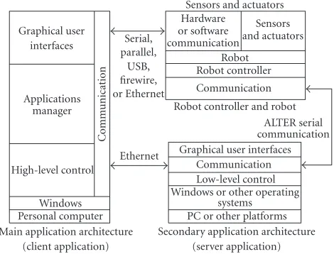
The experimental system used consists of a Puma 761 robotic manipulator and two personal computers. PSVS is mounted on the end effector of the robotic manipulator. The first com-puter communicates with the Puma robot controller through the available ALTER port. This is a special serial port for real-time communication (28 ms/cycle). The baud rate has been determined at 38 400 bps making some changes in the serial board of the Puma controller (the standard and the unique baud rate, as it has been determined by Unimation, was 19 200 bps). Even though Windows operating systems are used (it is not a real-time operating system; there are problems with latencies), a stable communication, in real-time, between the controller and the server was achieved. The second computer is used as a client computer and commu-nicates with the server through Ethernet. These devices (PCs and the robot controller) cooperate robustly and reliably by means of the robotic applicationHumanPT(Figure 2). It has been developed in visual C++ (more than 70 000 lines of code).
Main application architecture (client application) Personal computer Windows High-level control Applications manager Graphical user interfaces C o mm unication
Secondary application architecture (server application) PC or other platforms Windows or other operating
systems Low-level control Communication Graphical user interfaces Robot controller and robot
ALTER serial communication Communication Robot controller Robot Hardware or software communication Sensors and actuators Sensors and actuators
Ethernet Serial, parallel, USB, firewire, or Ethernet
Figure2: HumanPT architecture.
The application is executed in both computers. In the first one, a light version of it permits the reliable and robust communication of the PC with the robot controller. At the same time, it permits the low-level control of the Puma robot through ALTER port and the communication through Eth-ernet with the client computer. In the client computer, the full version is executed. Some features of the full version are (a) communication with the server computer through Ether-net, (b) calibration of cameras, (c) hand-eye calibration, (d) mirrors alignment check, (e) methods for path generation by means of a vision system, (f) control of the manipulator by means of several sources of data, and (g) real-time control by using visual servoing.
4. TARGET-OBJECT DESCRIPTION AND POSE ESTIMATION
The objective of this section is to calculate initially the state vector of a pointG(and of the frame attached to it) that be-longs to TOB.
(a)
(b) (c)
w v u
G U Ra
Rb
A
B C
V W
P v1
u1
w1
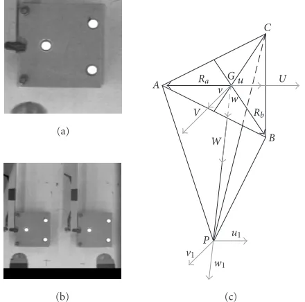
Figure3: Pictures and the schematic diagram of the target-object. (a) Top view of the TOB in which three dots of the dot display are depicted. (b) A complex image that has been captured by means of PSVS. (c) Schematic diagram of the TOB with the coordinate systems.A,B, andCare the centers of the three light sources while P(endpoint of a metal driver) is found at the invisible side of the TOB.
Moreover, to increase measurements accuracy, these sources are selected to be planar. Instead of using three sim-ple LEDs, a 5×7 dot matrix display has been used. The se-lection of the sources location (dots) is made by means of an electronic circuit or an aluminum mask adapted on the display. The TOB, as it is already presented, is mounted on an aluminum bar (Figure 4a). The coordinates of the origin G(gx,gy,gz) with respect to the camera frame are the mean
values of the coordinates of the three points A(ax,ay,az),
B(bx,by,bz), C(cx,cy,cz). Then the vectors Ra(rax,ray,raz)
andRb(rbx,rby,rbz) are defined asRa = GAandRb = GB
(Figure 3c). The vertical vectorW(Wx,Wy,Wz) to the plane
with origin G is given as W = Rb×Ra, while the vector U(Ux,Uy,Uz) is defined to be equal to−Ra, that is,U= −Ra.
Then, the third vectorV(Vx,Vy,Vz) is computed as the cross
product of the two previous vectors,V=W×U. The three vectors created in this way are vertical to each other and have the same originG(gx,gy,gz). The unit vectors derived from
them are
u= U
|U|, v= V
|V|, w= W
|W|, (7)
and compose a rectangular coordinate system attached to the point G(TOB frame). If the rotation matrices, derived by the above three unit vectors and the coordinates of the origin with respect to the camera frame are of the form
CR
G =[uvw] andCtG = [gx,gy,gz]T, respectively, then the
homogeneous matrix with respect to the camera frame is of
(a)
(b)
(c)
Figure4: (a) The TOB is attached to an aluminum bar. (b) Bot-tom side; the dot matrix display and the needle attached to the bot-tom side of the TOB stainless needle are distinguished. (c) Different types of TOB drivers that can be attached to the bottom side of the TOB. Thus, for instance, the operator can drive the TOB along an edge (a line) with a constant angle.
the form
CT G=
CR
G CtG
0T 1
. (8)
In each cycle, a gray scale imageI(i,j) is captured by using PSVS and is converted to a binary image with a prespecified threshold (T) by means of the software and the graphical user interface, which are parts ofHumanPT(Figure 5).
The binary imageIb(i,j) is inverted to the final image Iin(i,j), which contains only six black circular areas.
Figure5: The graphical user interface (GUI) used in the proposed method.
is propagated to the whole shape (the black circular area), scanning in a small area with a center this seed that includes the circular area. The procedure is repeated until all the cular shapes are segmented. For three light sources, six cir-cular shapes are appearing in the complex image captured by means of PSVS (Figure 3b). The algorithm finds the centers of these areas with subpixel accuracy. The correspondence problem is limited to three pairs of points (the centers of the circular areas). During system operation, only two points are found in the same scan line (epipolar line), which are the two different views of the centers of a circular area in the complex image. Thus, each pair is detected, its points are examined, and, if necessary, are set in correct order. From these three pairs, by means of (4), coordinates of each 3D point with re-spect to the camera frame are calculated.
We define matrixFT
Cas the homogeneous matrix
aris-ing from the solution of hand-eye calibration problem [42], found with a previous procedure and matrixWT
Fas the
ho-mogeneous matrix giving the location of the flange of the manipulator with respect to the world frame. The last
ma-X ma-X ma-X ma-X C ma-X ma-X ma-X ma-X X X X X C X X X X X X X X C X X X X X X X X C X X X X C C C C C C C C C X X X X C X X X X X X X X C X X X X X X X X C X X X X X X X X C X X X X
Figure6: Seeds can be found by means of the illustrated cross-type 9×9 template. “C”: black pixels. “X”: don’t care pixels.
trix is provided in each cycle (28 milliseconds) by the system using the ALTER communication port at 38 400 bps. Then the coordinates of a point with respect to the world frame, established on the base of the Puma 761 robotic manipula-tor, are derived by means of the transformation matrixWT
G
which equals WT
G = WTF·FTC·CTG. Euler angles yaw,
pitch, and roll are computed from the final rotation matrix
WR
G. Thus a six-component vector expressing the state of
the TOB frame is created. If (xWG,yWG,zWG) are the
co-ordinates of point G with respect to the world frame and (ψWG,θWG,ϕWG) are Euler angles yaw, pitch, and roll, then
this vector isXWG=(xWG,yWG,zWG,ψWG,θWG,ϕWG)T and
it is stored in a file.
The basic steps of the algorithm used are the following.
(1) Capture a complex image.
(2) Convert to a binary image and then mask the binary image (if necessary).
(3) Invert this image (if this property has been selected). (4) Automatically put a seed to each shape, propagate it,
and find the mean value of shape pixels location (sub-pixel accuracy).
(5) Calculate the coordinates of points in 3D space. (6) Calculate the three vectors of the TOB frame. (7) Calculate the homogeneous matrixCT
G.
(8) Find the transformation matrix of the TOB frame with respect to the world frame by means of the product
WT
G=WTF·FTC·CTG.
(9) Find from the final rotation matrix,WR
G, Euler angles
yaw, pitch, and roll (ψWG,θWG,ϕWG).
(10) Create the six-component vector with the position and orientation of the TOB frame that is equal toXWG =
(xWG,yWG,zWG,ψWG,θWG,ϕWG, )T and store the
vec-tor.
(11) Calculate the new desired location. (12) Repeat steps 1–11.
TOB follows a given edge, we assume that the point of inter-est (point of the desired path) is found initially along with the straight line passing from pointG, vertically to the sur-face of the light sources at the invisible side (bottom side) of the TOB (Figures 3c,4b). By construction, this point is the endpoint of a metal driver (i.e., a needle) attached to the TOB. InFigure 4csome types of metal drivers are illustrated. By means of the proper metal driver, the operator can drive the TOB along a line with a prespecified angle or angles (i.e., 15◦). This angle could be, for instance, the angle the torch forms with a welding line. Thus, an operator can drive the endpoint of the driver attached to the TOB along the edges of an object and then the recorded state vectors of that point correspond to points of a desired path. Let this point be the pointP(px,py,pz) (Figure 3c). It will be the forth vertex of
a pyramid. The other three vertices are the geometric cen-ters of the light sources. To calculate the state vector of point P, we define first a frame with that point an origin. LetGR
P
represent the rotation matrix that rotates theu1v1w1frame
(originP) with respect to theuvwframe (originG) and let vectorGt
Prepresent the translation of pointPwith respect to
pointG. The homogeneous matrix transforming the pointP frame to the TOB frame is of the form
GT P=
GR
P GtP
0 1
. (9)
By definition the frame attached to pointPis parallel to the TOB frame. Then the matrixGR
P equals the unit matrixI,
namely,GR
P=I. If pointPis found alongw-axis, thenGtP=
(0, 0,d)T, wheredis the Euclidean distance between points
P andG. In this case the location of the endpointPcan be estimated without any calibration of the TOB and the metal driver adapted on it, by means of the existing geometry.
In the general case, the relative location of the frame at-tached toP with respect to the TOB frame is estimated by means of the calibration procedure proposed below.
4.1. Calibration of the driver attached to the TOB
To estimate the location of the pointP with respect to the geometric centerGof the TOB, first, the coordinates of a 3D point P(px,py,pz) are estimated with respect to the world
frame by means of PSVS. Let the vectorCt
Pbe estimated by means of PSVS and (4). Then, the homogeneous matrixWt
P is calculated as
Wt
P=WTF·FTC·CtP. (10)
Point Pcoordinates are accurately estimated as the center of the pattern of a 2D object (i.e., a circle, a rectangle, or a square area in which the location of the geometric center (GC) is found easily). This point is computed with subpixel accuracy for each view in image coordinates and then, by im-plementing PSVS equations, point coordinates with respect to the world frame are calculated. This procedure is repeated for a numberNof different poses of the robotic manipulator
and PSVS mounted on it. The mean values of these coordi-nates provide the coordicoordi-nates of the pointPwith respect to the world frame
Wt P= 1
N
Wt
Pi. (11)
Then, coordinates of pointPwith respect to TOB frame are calculated by locating the endpoint of the TOB driver on the GC of the pattern (pointP). The proposed visual servo con-trol algorithm is set in operation and the operator, retaining this contact of the endpoint of the TOB driver on the GC of the pattern, rotates the TOB. After an initial translation and rotation of PSVS to approach and keep the TOB in the proper view, PSVS tracks the TOB while at the same time the different states of the pointG and the frame attached to it are recorded. For each state, the vector providing the coordi-nates of pointPwith respect to pointG,Gt
P, is estimated by
the following multiplications and matrices inversions:
Wt
P=WTF·FTC·CTG·GtP=⇒ Gt
P=CT−G1·FTC−1·WT−F1·WtP.
(12)
The vector Wt
P ≡ WtP and the matrix FTC have been es-timated by the already mentioned procedure while matrices
CT
GandWTFare provided for each loop cycle. To find
vec-torGt
Pas accurately as possible, ifNrepresents the number
of the different vectors recorded by the system, it is calcu-lated as the mean value of the estimated vectors by means of the above procedure, that is,
Gt P=
1 N
Gt
Pi. (13)
The numberNof vectors is prespecified by means of the GUI
(Figure 5, bottom).
5. PSEUDO STEREO VISUAL SERVO CONTROL
As it has already been mentioned, the control method used is a pose-based pseudo stereo visual control method. The term pseudo is used because one complex image per cycle is processed. To implement an endpoint closed-loop (ECL) visual servoing, two points (a real and a desired point) and the frames attached to them are considered. The first frame is the TOB frame. Without loss of generality, we consider as desired point a virtual point in 3D space,D(dx,dy,dz), found
on thez-axis (dx=0, dy=0) of the camera frame, and the
frame attached to it is parallel to the camera frame. Thus, the distance between the TOB frame and the camera frame can be regulated by means of the GUI. As PSVS moves, it keeps the TOB in the field of view while the virtual point tracks TOB’s frame origin. In the general case, the virtual desired point can be selected so that its double track on the image plane exists. When the tool tip (mounted on the end effector of the manipulator) tracks a Cartesian path, the desired point frame can be the tool tip frame. Poses of the above frames are estimated with respect to the robot flange frame. LetCT
be the homogeneous matrix giving the pose of the desired pointDframe to the camera frame. The homogeneous ma-tricesFT
G,FTDgiving the poses of the TOB frame and the
de-sired pointDframe to the robot flange frame are derived by means of the following products:FT
G=FTC·CTGandFTD= FT
C·CTD. If (xFG,yFG,zFG), (xFD,yFD,zFD) are coordinates
of points G and D, respectively, to the flange frame and (ψFG,θFG,ϕFG), (ψFD,θFD,ϕFD) are the related Euler angles
(yaw, pitch, and roll) to the camera frame, then the current state vectorXFG=(xFG,yFG,zFG,ψFG,θFG,ϕFG)Tand the
de-sired state vectorXFD = (xFD,yFD,zFD,ψFD,θFD,ϕFD)T are
calculated with respect to the robot flange frame by means of these matrices. Then, a kinematic error function with respect to the flange frame can be simply written asEF=XFG−XFD.
The relation is valid when small changes in angles per cycle are appearing and in this case angles yaw, pitch, and roll may be used as a 3×1 vector [43]. The low-level control algorithm implemented in the robot system through ALTER port deter-mines the maximum limits for safe and reliable operation of the robotic manipulator. Thus the above constraint for small angle changes/cycle is always valid. LetKbe a 6×6 weight matrix. Then the 6×1 kinematic screw of the robot flange is
VF= −K·EF.
6. EXPERIMENTAL RESULTS
The robot path generation method described above has been implemented by means of a Puma 761 robotic manipulator and two PCs (running at 350 MHz). The graphical user in-terface (GUI) permits offset regulation of the distancedzof
PSVS (mounted on the end effector of the robotic manipula-tor) from the virtual point. An operator can also select some more operations like inversion of images, threshold selection, recording delay (sampling rate), and saving facilities.
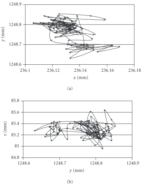
The low-level step controller of the system is regulated to maximum speed values of 100 mm/s and 60 deg/s for trans-lation and rotation, respectively. The recording delay was de-fined to 10 cycles/vector. The measured cycle of the servo loop (control + recording) was 70 milliseconds. To show the accuracy and the precision of the system, the TOB remains stationary and the robot system is activated. After an ini-tial translation and rotation of PSVS (of the virtual point) to track the TOB, it continues to track the TOB, while at the same time state vectors are recorded (106 vectors). In Figures 7a,7byversusxandzversusyare illustrated, respectively.
The real TOB state with respect to the world frame is the following: xWG = 236.132 mm, yWG = 1248.772 mm,
zWG=85.284 mm,ψWG= −2.598◦,θWG= −0.883◦,ϕWG=
−4.535◦. It was accurately estimated by means of PSVS. Then by using the recorded state vectors, the mean error (ME), the mean absolute error (MAE), the maximum error (MaxE), and the standard deviation (SD) are calculated. The results are presented inTable 1.
To show the accuracy of the system as the TOB moves, the TOB with its aluminum bar is attached to a rotated base
(Figure 8a).Figure 8ashows also PSVS mounted on the end
effector of the robotic manipulator. The coordinates of the center of this base (in mm) with respect to the world frame
236.1 236.12 236.14 236.16 236.18
x(mm) 1248.6
1248.7 1248.8 1248.9
y
(mm)
(a)
1248.6 1248.7 1248.8 1248.9
y(mm) 84.8
85 85.2 85.4 85.6 85.8
z
(mm)
(b)
Figure7: (a) Graph ofyversusxand (b)zversusyas PSVS tracks the stationary TOB. Coordinates are considered with respect to the world frame.
are the following: (xb,yb,zb) = (147.5, 1378.5, 448.0) while
the radius of the circle is 246 mm. The distancedz is
deter-mined to bedz=600 mm. The initial angle indicated by the
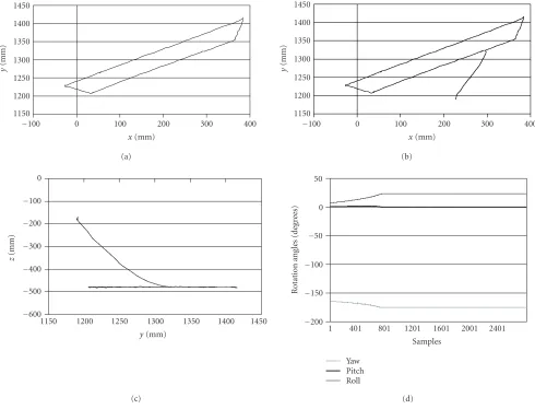
base angle index is 50◦. The robot system is activated and PSVS (the virtual point) tracks the TOB in its initial loca-tion. The operator rotates the TOB while the state vectors are recorded. PSVS keeps the TOB in the field of view. The sys-tem stops when the base index is about−50◦. InFigure 8b the generated arc is depicted while in Figures8cand8dthe variation of the position and of the rotation angles are illus-trated, respectively. FromFigure 8dit is concluded that an-gle changes are less than ±1.5◦. By means of the state vec-tors recorded, the mean error (ME), the mean absolute error (MAE), and the maximum error (MaxE) are calculated. The results are presented inTable 2.
As a third experiment, we drove the TOB along the edges of a trapezium-shaped aluminum piece. Its dimensions are b1 = 451 mm, b2 = 361 mm, and h = 45 mm. First the
endpoint of the needle (the driver attached to the TOB) is estimated. The path generated is illustrated in Figure 9a.
In Table 3, as mentioned previously, the calculated errors
Table1: Errors and standard deviation as PSVS tracks the TOB found in a static location (mm).
Error xWG yWG zWG ψWG θWG ϕWG
ME 1.13E-13 −4.3E-15 2.44E-14 −6.1E-16 1.0E-15 −8.8E-15
MAE 0.0089 0.0412 0.0949 0.0056 0.0026 0.0039
MaxE 0.0369 0.1403 0.352 0.2972 0.1401 0.2041
SD 0.0116 0.0508 0.1170 0.0290 0.0137 0.0199
(a)
0 100 200 300 400
x(mm) 1100
1150 1200 1250 1300
y
(mm)
(b)
x y z
1 101 201 301 401 501
Samples −3
−2 −1 0 1 2
P
o
sition
var
iation
(mm)
(c)
Yaw Pitch Roll
1 101 201 301 401 501
Samples −2
−1.5 −1 −0.5 0 0.5 1 1.5 2
R
o
tation
ang
le
var
iation
(deg
re
es)
(d)
Figure8: (a) A picture of the robotic system. (b) The graph ofyversusx. (c) Variation of the position of the TOB. (d) Variation of the rotation angles of the TOB. Coordinates in Figures8b,8c,8dare considered with respect to the world frame.
Table2: Errors as PSVS tracks the TOB following a circular path (mm).
Error xWG yWG zWG ψWG θWG ϕWG
ME 0.0436 0.1093 −0.294 0.1795 −0.0472 −0.1662
MAE 0.2466 0.4843 0.3048 0.6212 0.4581 0.4313
MaxE 1.1477 1.7052 1.0210 1.8740 1.7380 0.8604
During real-time operation, Puma 761 is supplied with the recorded vectors of the previous generated path. The tool tip begins from an initial location and then follows the gener-ated path. The results for two planes are illustrgener-ated in Figures 9band9cwhile inFigure 9dthe graph of angles with respect to the recorded samples (one sample/cycle) is illustrated.
6.1. Discussion
−100 0 100 200 300 400
x(mm) 1150
1200 1250 1300 1350 1400 1450
y
(mm)
(a)
−100 0 100 200 300 400
x(mm) 1150
1200 1250 1300 1350 1400 1450
y
(mm)
(b)
1150 1200 1250 1300 1350 1400 1450
y(mm) −600
−500 −400 −300 −200 −100 0
z
(mm)
(c)
Yaw Pitch Roll
1 401 801 1201 1601 2001 2401 Samples
−200 −150 −100 −50 0 50
R
o
tation
ang
les
(deg
re
es)
(d)
Figure9: (a) Path generated by means of a trapezium-shaped aluminum piece. Real-time implementation: (b) graphyversusx, (c) graph zversusy, and (d) graph of rotation angles with respect to recorded samples. Coordinates are considered with respect to the world frame.
Table3: Errors as PSVS tracks the TOB following a trapezium-shaped path (mm).
Error xWG yWG zWG ψWG θWG ϕWG
ME 0.1376 −0.428 −4E-04 0.0007 −7E-04 0.0008
MAE 0.9949 0.7873 0.392 0.822 0.8333 1.0736
MaxE 3.934 3.8898 1.344 3.181 2.588 3.276
by selecting the proper metal driver. The control loop is ro-bust and light sources remain in the field of view of PSVS, in an almost steady position, if TOB velocities are smaller than robot velocities. In any other case, for safety reasons, the robot remains in its last state or it returns to an initial prespecified state (Figure 5, Stop on Current Location check box). Moreover the software developed examines cases where only one or two light sources are found in the field of view of PSVS. Then, only position control is possible. However, cur-rent TOB state can accurately be recorded if PSVS is carefully calibrated.
7. CONCLUSIONS
X X X X C X X X X X X X X C X X X X X X X X C X X X X X X X X C X X X X C C C C C C C C C X X X X C X X X X X X X X C X X X X X X X X C X X X X X X X X C X X X X
X X C X X X X C X X C C C C C X X C X X X X C X X
(a)
S X X X X X X X X X C X S X X X X X X X C X X X S X X X X X C X X X X X S X X X C X X X X X X X S X C X X X X X X X X X C X X X X X X X X X S X S X X X X X X X S X X X S X X X X X S X X X X X S X X X S X X X X X X X S X S X X X X X X X X X S
(b)
S X X X X X X X X X C X S X X X X X X X C X X X S X X X X X C X X X X X S X X X C X X X X X X X S X C X X X X X X X X X S X X X X X X X X X S X S X X X X X X X S X X X S X X X X X S X X X X X S X X X S X X X X X X X S X S X X X X X X X X X S
(c) (d)
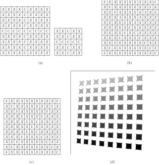
Figure10: Corner detection algorithm. (a) Cross-shape templates, (b)X-shape template for corner detection, “C” type, (c)X-shape tem-plate for corner detection, “S” type, and (d) the ordered segmentation of squares and corners detected are illustrated.
robot and reported problems of ALTER port [38], the pseudo stereo visual servo loop, as presented, ensures the robustness of the system and the recently developed PSVS the accuracy of measurements. The proposed method can be applied in manipulators or in mobile robots to generate any path just following the moving TOB. Drivers attached to the TOB may be replaced according to the requirements of each applica-tion.
APPENDIX
The corner detection algorithm proposed in [41] was devel-oped to support Zhang calibration method [40]. It finds cor-ners in a pattern with squares by means of templates even in cases where squares in images have big slope or images are distorted due to camera lens. While, in general, it is consid-ered that template-based methods are slower than geometry-based algorithms; the algorithm is fast enough because a small number of pixels of the proposed templates are used.
Two basic concepts are used. The first one concerns the method of separating each square of the binary image. For this reason the concept of seed is used, that is, a pixel with a unique specified color or gray scale value. In patterns, in
which shapes can be considered as separated entities, in each shape (i.e., a square) a seed is planted. Then, this seed can be propagated only to this entity. In this way, the segmentation of an image is possible and, if it is desired, with a specified order of the created segments. The last idea is implemented in the proposed algorithm. The segmentation order is spec-ified using as features for the estimation of the new seed the center and the slope of the previous segmented square. Two criteria for the selection of a seed are used. The first is its dis-tance from a specified initial point. The second criterion is the following: the candidate pixel must be the center pixel of a 9×9 or 5×5 template (the template used depends on the case) with cross-shape (Figure 10a). The last criterion is used to make the pixel selection insensitive to noise.
“don’t care” pixels. In the first template (Figure 10b) the cen-ter pixel is type “C” and in the second template (Figure 10c) the center pixel is type “S.”
As it is easily realized from these figures the templates are “X” shape where one leg is colored with the square color and the other three legs are colored with the substrate color. The detecting pixel is the center pixel of the templates. Ro-tating these two basic templates 90◦each time and then ap-plying them to the image, the detection of all corner pixels is possible. The interesting corner point is the peak formed around corner area from the change of the substrate color to the square color and vice versa. This peak may be the mean value of two pixels in a well-formed square in a binary image or the mean value of many detected pixels, creating a cluster of pixels around the corner, using the above templates in a binary, gray scale, or color image. Using these slightly diff er-ent types of templates the inner and the outer side pixels of the corner are simultaneously detected. The result of ordered segmentation and corner detection is depicted inFigure 10d. A complete algorithm for corner detection, as well as calibra-tion facilities by means of the proper graphical user interfaces (parts of HumanPT application), is also provided.
REFERENCES
[1] J. T. Feddema and O. R. Mitchell, “Vision-guided servoing with feature-based trajectory generation,”IEEE Trans. Robot. Automat., vol. 5, no. 5, pp. 691–700, 1989.
[2] Y. Kuniyoshi, M. Inaba, and H. Inoue, “Learning by watching: extracting reusable task knowledge from visual information of human performance,”IEEE Trans. Robot. Automat., vol. 10, no. 6, pp. 799–822, 1994.
[3] A. Ude and R. Dillmann, “Trajectory reconstruction from stereo image sequences for teaching robot paths,” inProc. 24th International Symposium on Industrial Robots (ISIR ’93), pp. 407–414, Tokyo, Japan, November 1993.
[4] A. Ude and R. Dillmann, “Vision-based robot path planning,” inAdvances in Robot Kinematics and Computational Geom-etry, pp. 505–512, Kluwer Academic Publishers, Dordrecht, The Netherlands, 1994.
[5] A. Ude and R. Dillmann, “Robot motion specification: a vision-based approach,”Surveys on Mathematics for Industry, vol. 5, no. 2, pp. 109–131, 1995.
[6] S. Kang, Robot instruction by human demonstration, Ph.D. thesis, Robotics Institute, Carnegie Mellon University, Pitts-burgh, Pa, USA, 1994.
[7] B. Brunner, K. Arbter, G. Hirxinger, and R. Koeppe, “Pro-gramming robots via learning by showing in a virtual envi-ronment,” inProc. Virtual Reality World ’95, IDG Conferences and Seminars, pp. 63–72, Munich, Germany, 1995.
[8] R. Voyles and P. K. Khosla, “Gesture-based programming, part I: a multi-agent approach,” inProc. ANNIE: Artificial Neural Networks, Fuzzy Logic and Evolutionary Programming for Designing Smart Engineering Systems, pp. 299–304, ASME Press, St. Louis, Mo, USA, November 1996.
[9] C. G. Johnson and D. Marsh, “Modeling robot manipulators in a CAD environment using B-splines,” inProc. IEEE Interna-tional Joint Symposia on Intelligence and Systems (IJSIS ’96), N. G. Bourbakis, Ed., pp. 194–201, Rockville, Md, USA, Novem-ber 1996.
[10] P. N. Sabes,The planning of visually guided arm movements: feedback perturbation and obstacle avoidance studies, Ph.D. thesis, MIT, Cambridge, Mass, USA, 1996.
[11] L. F. Gu, “Visual guidance of robot motion,” M.S. thesis, Uni-versity of Western Australia, Crawley, Western Australia, 1996. [12] M. P¨aschke and J. Pauli, “Vision based learning of gripper tra-jectories for a robot arm,” inProc. International Symposium on Automotive Technology and Automation, pp. 235–242, Flo-rence, Italy, 1997.
[13] R. Sharma and H. Sutanto, “A framework for robot motion planning with sensor constraints,” IEEE Trans. Robot. Au-tomat., vol. 13, no. 1, pp. 61–73, 1997.
[14] E. Berry, P. Martinet, and J. Gallice, “Trajectory generation by visual servoing,” inProc. IEEE/RSJ International Conference on Intelligent Robots and Systems (IROS ’97), vol. 2, pp. 1066– 1072, Grenoble, France, September 1997.
[15] A. Ruf and R. Horaud, “Visual trajectories from uncalibrated images,” in Proc. Workshop on New Trends in Image-Based Robot Servoing, Proc. IEEE/RSJ International Conference On Intelligent Robots and Systems, pp. 83–91, Grenoble, France, September 1997.
[16] P. Kim, S. Rhee, and C. H. Lee, “Automatic teaching of weld-ing robot for free-formed seam usweld-ing laser vision sensor,” Op-tics and Lasers in Engineering, vol. 31, no. 3, pp. 173–182, 1999.
[17] X. F. Zha and H. Du, “Generation and simulation of robot trajectories in a virtual CAD-based off-line programming en-vironment,”International Journal of Advanced Manufacturing Technology, vol. 17, no. 8, pp. 610–624, 2001.
[18] Y. Mezouar and F. Chaumette, “Path planning for robust image-based control,”IEEE Trans. Robot. Automat., vol. 18, no. 4, pp. 534–549, 2002.
[19] T. Pachidis, J. Lygouras, and P. Tsalidis, “A graphical user in-terface for the initial path generation of a robotic manipulator for an arc welding system,” inProc. 2nd WSEAS International Conference on Robotics, Distance Learning and Intelligent Com-munication Systems (ICRODIC ’02), pp. 1601–1607, Skiathos Island, Greece, September 2002.
[20] B. Espiau, F. Chaumette, and P. Rives, “A new approach to vi-sual servoing in robotics,”IEEE Trans. Robot. Automat., vol. 8, no. 3, pp. 313–326, 1992.
[21] N. P. Papanikolopoulos, P. K. Khosla, and T. Kanade, “Visual tracking of a moving target by a camera mounted on a robot: a combination of control and vision,”IEEE Trans. Robot. Au-tomat., vol. 9, no. 1, pp. 14–35, 1993.
[22] W. Wilson, C. Hulls, and G. Bell, “Relative end-effector con-trol using cartesian position-based visual servoing,” IEEE Trans. Robot. Automat., vol. 12, no. 5, pp. 684–696, 1996. [23] P. Martinet, “Comparison of visual servoing techniques:
ex-perimental results,” in Proc. European Control Conference (ECC ’99), pp. 1059–1064, Karlsruhe, Germany, August– September 1999.
[24] E. Cervera and P. Martinet, “Visual servoing with indirect image control and a predictable camera trajectory,” inProc. IEEE/RSJ International Conference on Intelligent Robots and Systems (IROS ’99), vol. 1, pp. 381–386, Kyongju, South Ko-rea, October 1999.
[25] J. A. Gangloffand M. F. de Mathelin, “Visual servoing of a 6-DOF manipulator for unknown 3-D profile following,”IEEE Trans. Robot. Automat., vol. 18, no. 4, pp. 511–520, 2002. [26] R. Mahony, T. Hamel, and F. Chaumette, “A decoupled image
space approach to visual servo control of a robotic manipu-lator,” inProc. IEEE International Conference on Robotics and Automation (ICRA ’02), vol. 4, pp. 3781–3786, Washington, DC, USA, May 2002.
[28] B. Thuilot, P. Martinet, L. Cordesses, and J. Gallice, “Position based visual servoing: keeping the object in the field of vi-sion,” inProc. IEEE International Conference on Robotics and Automation (ICRA ’02), vol. 2, pp. 1624–1629, Washington, DC, USA, May 2002.
[29] E. Malis, “Vision-based control invariant to camera intrinsic parameters: stability analysis and path tracking,” inProc. IEEE International Conference on Robotics and Automation (ICRA ’02), vol. 1, pp. 217–222, Washington, DC, USA, May 2002. [30] G. Hager, “A modular system for robust positioning using
feedback from stereo vision,” IEEE Trans. Robot. Automat., vol. 13, no. 4, pp. 582–595, 1997.
[31] B. Lamiroy, B. Espiau, N. Ahdreff, and R. Horaud, “Con-trolling robots with two cameras: how to do it properly,” in
Proc. IEEE International Conference on Robotics and Automa-tion (ICRA ’00), pp. 2100–2105, San Fransisco, Calif, USA, April 2000.
[32] E. Malis, F. Chaumette, and S. Boudet, “Multi-cameras visual servoing,” inProc. IEEE International Conference on Robotics and Automation (ICRA ’00), vol. 4, pp. 3183–3188, San Fran-cisco, Calif, USA, April 2000.
[33] E. Cervera, F. Berry, and P. Martinet, “Stereo visual servoing with a single point: a comparative study,” inProc. 9th IEEE International Conference on Advanced Robotics (ICAR ’01), pp. 213–218, Budapest, Hungary, August 2001.
[34] P. Martinet and E. Cervera, “Stacking jacobians properly in stereo visual servoing,” inProc. IEEE International Conference on Robotics and Automation (ICRA ’01), pp. 717–722, Seoul, Korea, May 2001.
[35] P. Martinet and E. Cervera, “Image-based stereo visual servo-ing: 2D vs 3D features,” inProc. IEEE International Conference on Robotics and Automation (ICRA ’02), vol. 2, pp. 1630–1635, Washington, DC, USA, May 2002.
[36] S. Hutchinson, G. Hager, and P. Corke, “A tutorial in visual servo control,”IEEE Trans. Robot. Automat., vol. 12, no. 5, pp. 651–670, 1996.
[37] T. Pachidis and J. Lygouras, “A pseudo stereo vision system as a sensor for real time path control of a robot,” in Proc. 19th IEEE Instrumentation and Measurement Technology Con-ference (IMTC ’02), vol. 2, pp. 1589–1594, Anchorage, Alaska, USA, May 2002.
[38] G. Hager, S. Hutchinson, and P. Corke, “Tutorial TT3: a tu-torial on visual servo control,” inconjunction with IEEE Con-ference on Robotics and Automation, Minneapolis, Minn, USA, April 1996.
[39] T. Pachidis and J. Lygouras, “Pseudo stereo vision system: modifications for accurate measurements in 3-D space us-ing camera calibration,” inProc. ISA/IEEE Sensors for Indus-try Conference, pp. 66–70, Houston, Tex, USA, November 2002.
[40] Z. Zhang, “A flexible new technique for camera calibration,”
IEEE Trans. Pattern Anal. Machine Intell., vol. 22, no. 11, pp. 1330–1334, 2000.
[41] T. Pachidis, J. Lygouras, and V. Petridis, “A novel corner de-tection algorithm for camera calibration and calibration facil-ities,” inProc. 2nd WSEAS International Conference on Signal Processing and Computational Geometry and Vision, pp. 6911– 6916, Rethymno, Greece, July 2002.
[42] H. Zhuang, Z. S. Roth, and R. Sudhakar, “Simultaneous robot/world and tool/flange calibration by solving homoge-neous transformation equations of the form AX=YB,”IEEE Trans. Robot. Automat., vol. 10, no. 4, pp. 549–554, 1994. [43] S. G. Tzafestas,Robotic Systems: Advanced Techniques and
Ap-plications, Kluwer Academic Publishers, Boston, Mass, USA, 1992.
Theodore P. Pachidiswas born in Drama, Greece, in August 1962. He received the B.S. degree in physics and the M.S. degree in electronics from the Aristotle University of Thessaloniki in 1985 and 1989, respec-tively. Since 1989 he has been a Teacher of physics and electronics. He is currently working toward his Ph.D. degree in robotics and machine vision systems in the Depart-ment of Electrical and Computer
Engineer-ing, Democritus University of Thrace. From 1996 to 1998, he was a Schoolmaster of the Public Institute of Professional Training at Kavala. His interests include the design and construction of elec-tronic devices and systems, robotics, machine vision systems, vi-sual C++, and microcontroller programming. He is a Member of the IEEE and the IEEE Computer Society.
Kostas N. Tarchanidis received the Diploma degree in electrical engineering from the Democritus University of Thrace and his Ph.D. degree in robotics from the Department of Electrical Engineering and Electronics, University of Liverpool. He is presently an Associate Professor in the Department of Petroleum Technology, Technological Educational Institute of Kavala, Kavala, Greece. He is Dean of the
School of Engineering. He is a Member of the Technical Chamber of Greece and the IEEE.
John N. Lygouras was born in Kozani, Greece, in May 1955. He received the Diploma and the Ph.D. degrees in electrical engineering from the Democritus Univer-sity of Thrace, Greece, in 1982 and 1990, re-spectively, both with honors. From 1982 he was a Research Assistant and since 2000 he has been an Associate Professor in the De-partment of Electrical and Computer Engi-neering, Democritus University of Thrace.
In 1997 he spent six months in the Department of Electrical En-gineering and Electronics, the University of Liverpool, as a Hon-orary Senior Research Fellow. His research interests are in the field of robotic manipulators trajectory planning and execution. His in-terests also include the research on analog and digital electronic sys-tems implementation and position control of underwater remotely operated vehicles.
Philippos G. Tsalideswas born in Mirina Limnou, Greece, on October 14th, 1953. He received the Diploma degree in electronic engineering from the University of Padova, Italy, in 1979, and the Ph.D. degree in electrical engineering from the Democritus University of Thrace, Greece, in 1985. He is a Professor of applied electronics in the De-partment of Electrical and Computer Engi-neering, Democritus University of Thrace.