University of Twente
Faculty of Electrical Engineering, Mathematics & Computer Science
Formal Methods and Tools
Graph-Based Semantics of the
.NET Intermediate Language
by
N.B.H. Sombekke
May, 2007
Graduation Committee:
dr. ir. A. Rensink (1st supervisor)
ir. H. Kastenberg
Abstract
The semantics of a programming language are often described in a natural language. Such de-scriptions are often ambiguous and hard (or even impossible) to construct in a precise way. To tackle these problems one could specify a formal description of the semantics by using a mathe-matical model. In this report such a mathemathe-matical model is presented for the .NET Intermediate Language (IL) in the form of graphs and transformations to these graphs.
In order to be able to perform transformations on graphs, we need a start graph. The .NET In-termediate Language generates bytecode and cannot supply such a start graph. Therefore we have constructed a translator that translates an arbitrary IL program into a so called Abstract Syntax Graph (ASG). The ASG is the start graph to which we now can apply graph transformations.
Contents
2.1.3 Common Type System and Common Language Specification . . . 10
2.1.4 Types . . . 11
3 Graphs and Graph Transformations 21 3.1 Graphs . . . 22
4 Translating IL Programs to Graphs 27 4.1 Translator . . . 27
4.2 Meta-Model Abstract Syntax Graph . . . 28
4.2.1 High-level structure . . . 28
4.2.3 Attributes . . . 31
5 Specifying IL Semantics with Graph Transformations 41 5.1 Static Analysis . . . 41
5.3.4 Method Frame Representation and Transferring Arguments . . . 51
5.4 Production rules . . . 54
A IL programs side to side 77
B Calculator Example: IL Code and ASG 81
Chapter 1
Introduction
Probably everybody has experienced a time that a communication problem between two persons appeared. For example, when your mother asked you to get a bread from the bakery and that when you were at the bakery you did not know what bread to take.
Formally speaking, executing the task can have a different result than the person who gave the task had in mind. Something similar holds for the meaning and behaviour (semantics) of programming languages. When describing the semantics of programming languages in a natural language (such as English), this can lead to ambiguity. Furthermore, by using a natural language to describe semantics of a programming language it is hard (or even impossible) to present the semantics in a precise way. It is also easy to introduce mistakes or forget details. Take for example an instruction which adds two values. It is easy to forget specific details of where these two values can be found, or where the result of this operation should be stored.
To tackle these problems, one should specify the semantics in a formal way. This specification is represented in the form of a mathematical model and can serve as a basis for understanding and formal reasoning about the behaviour of programs. It is also useful for precisely defining the meaning of program constructions. When giving a formal description, details that are normally easily overseen will be unrevealed and made explicit, leaving no space for ambiguity. Another advantage of using a mathematical model is that it opens possibilities for analysis and verification. There are several formal languages for expressing semantics of a programming language. The
Structural Operational Semantics (SOS) approach, introduced by Plotkin[20] in 1981, has been very popular. SOS generates a transition system by using logical rules. Due to these logical rules, SOS can be hard to grasp for persons unfamiliar with logic. Also see [1,27] for more information about SOS.
A more recent technique of giving a formal description of semantics is by using graphs and applying transformations to these graphs. A graph is used to model a state of a program, and the graph transformations are an intuitive, easy to understand, and a clear way to express the behaviour of the program in a rule-based way, just as with SOS. Using graphs is especially useful for representing object-oriented programs because the states of these programs mainly depend on a set of reference values. Furthermore, graph transformations lend themselves for describing dynamic changes to such states. To be able to work with graphs and graph transformations, a tool is needed to construct graphs and perform transformations to these graphs. There exist quite some tools on this, but in this work we use the GROOVE tool set[9].
transition system. In such a transition system states are represented by nodes, and transitions between states are represented by edges.
This thesis shows that graph transformations can be used for the specification of the semantics of a programming language, in particular the.NET Intermediate Language. We have chosen the .NET Intermediate Language because this is a low-level intermediary language which covers all other .NET languages. The relation of the .NET Intermediate Language and the other .NET languages can be explained using the analogy of an interpreter that translates Russian and Dutch to English. Here, English is analogous to the Intermediate Language, and Russian and Dutch to the other .NET languages. If you are able to understand English, you will also be able to understand the other languages when talking via the interpreter.
1.1
Problem Statement
The semantics of programming languages described by using natural languages can be ambiguous, meaning that a text can easily be open for multiple interpretations. On the other hand, pictures in the form of graphs and graph transformations are often more clear and less ambiguous than natural languages. Also, it is possible to reason about graphs and graph transformations thanks to their formal background [25]. Another motivation to use a graph-based representation is that graphs are a convenient way to represent the structure of a program, and graph transformations are a good technique to represent object-oriented behaviour.
Our interest is that we want to describe the semantics of an object-oriented programming language using graph transformations. We have chosen for the .NET Intermediate Language (IL) because all .NET languages are compiled to IL, which makes it attractive to do our research on IL instead of other .NET languages individually.
The main question now is: how can we describe the semantics of the .NET IL by using graph transformations? Therefore, the goal of this research project is the development of a graph-based specification of the semantics of the Microsoft .NET IL.
1.2
Approach
To accomplish the graph-based representation, we decided to construct a set of graph production rules specifying the semantics of the IL. When modelling the syntax and states of IL programs as graphs accordingly, we can apply the rules to those graphs, i. e. simulate the program. Figure1.1 contains an overview of these two steps.
.NET Intermediate Language
Figure 1.1: From program to simulations, an overview.
This figure shows that a translator translates a .NET Intermediate Language program into the Abstract Syntax Graph, to which graph production rules are applied. Both the translator
1.3 Overview 7
Translator We need a translator to construct a graph from an arbitrary IL program. This graph is an abstract syntax representation of the IL program, and therefore is called an Abstract Syntax Graph (ASG). The ASG contains the structure of the program, the instructions that have to be executed and the syntactic order of these instructions. During the static analysis phase, we enrich the ASG by creating and adding method signatures, transforming namespaces, and resolving identifiers.
Graph Production Rules Although static analysis is mostly performed in the translator, a minor part of static analysis will be performed by using a graph production rule in order to provide some intuition of what happens during static analysis. This involves merging of labels having the same identifier. Furthermore, the ASG contains implicit control flow information. A decision has to be made whether or not to make this control flow explicit by using a control flow analysis phase. The major goal of this project is the specification of the semantics of the .NET Intermediate Language by graph transformations. We aim at specifying the semantics with one or two transfor-mation rules per instruction. These graph production rules transform a graph, which in fact is the Abstract Syntax Graph delivered by the translator, into another graph. Each time a production rule from this graph transformation system is applied, a so called Execution Graph is created. Such a graph is a representation of a system state. Thus by applying the whole graph transforma-tion system to the Abstract Syntax Graph, we can simulate the IL program. By simulating the program atransition system is constructed, which consists of Execution Graphs (states) and the applied production rules (transitions) to these Execution Graphs .
1.3
Overview
Chapter 2
The .NET Framework
In the year 2000 Microsoft launched the .NET (pronounced: dot net) initiative. The .NET Frame-work is a development and runtime infrastructure that can be used for the development of appli-cations for the Windows platform.
The framework is designed to fulfil the following objectives [16]:
• To provide a consistent object-oriented programming environment whether object code is stored and executed locally, executed locally but Internet-distributed, or executed remotely.
• To provide a code-execution environment that minimizes software deployment and versioning conflicts.
• To provide a code-execution environment that promotes safe execution of code, including code created by an unknown or semi-trusted third party.
• To provide a code-execution environment that eliminates the performance problems of in-terpreted or scripted environments.
• To make the developer experience consistent across widely varying types of applications, such as Windows-based applications and Web-based applications.
• To build all communication on industry standards to ensure that code based on the .NET Framework can integrate with any other code.
This chapter contains an introduction to the .NET Framework and the Intermediate Language. First we will present an overview of the .NET Framework, what it contains and how it works. After that, more will be explained about the Intermediate Language. Most figures presented in this chapter are derived or based on figures from [19] and [6].
2.1
Overview of .NET
VB.NET …
Figure 2.1: Overview of Languages, Intermediate Language and Common Language Runtime
2.1.1
Common Language Runtime
The Common Language Runtime (CLR) is the runtime environment in which .NET applications are executed. Consider the CLR to be comparable to the Java Virtual Machine (JVM) (see [11]). Like JVM uses an intermediate language representation of Java (called bytecode), the CLR uses IL. IL code is sometimes referred to asmanaged code because the CLR manages its lifetime and execution [24]. To do this, the CLR provides necessary core services such as memory and thread management and strict type safety. Code that does not target the runtime is known asunmanaged code. Unmanaged code is for example native code (i. e. machine code).
The CLR uses a just-in-time (JIT) compiler to compile the IL code, which is stored in a so called Portable Executable file, into native (platform-specific) code. After this conversion, the native code is executed. This means that .NET code is always compiled, not interpreted. The usage of IL code and JIT compilation ensures that code is portable as well as efficient.
2.1.2
Base Class Library
The Base Class Library (BCL), sometimes also referred as .NET Framework Class Library (FCL) [24], is a library containing all important types (i. e. classes) of the .NET Framework. The BCL is language independent, meaning that it does not depend on the used .NET language. Furthermore, the BCL is available for all languages using the .NET Framework. The class library encapsulates a number of common functions such as file reading and writing, network programming and graphic rendering.
2.1.3
Common Type System and Common Language Specification
When different languages must cooperate with each other, some kind of agreement must exist on how this is accomplished. Therefore, theCommon Type System (CTS) is defined within the CLR, making it a fundamental part of the CLR. It defines the entire set of types that can be used with many different language syntaxes and makes it possible for two different .NET languages to use each other’s objects. Language compilers targeting the CLR must generate code that is conformant to the CTS. The CTS performs the following functions [16]:
• Establish a framework that helps enable cross-language integration, type safety, and high performance code execution.
2.1 Overview of .NET 11
• Define rules that languages must follow, which helps ensure that objects written in different languages can interact with each other.
It is possible for one language to allow a construct supported by the CTS, while another language does not. This can be a barrier for cross-language integration. Therefore, the Common Language Specification (CLS) is developed, which is a subset of the CTS. The CLS is a set of of basic language features needed by many languages[17]. It includes language constructs often required by many software developers, but is small enough for most languages to be able to support it.
CTS
C# VB.NET
J# CLS
Figure 2.2: Common Type System and Common Language Specification
For more information about the CTS and the CLS, see [6].
2.1.4
Types
The CLR distinguishes betweenvalue types andreference types [6,19,26].
Value types are used to describe values. Values are instances of value types. They are directly stored at the memory address on the method stack assigned by their variable, or inside an object in case of a field of an object. Value types must always contain some data and thus cannot be null. When passing value types as argument to a function, a copy of the value is made prior to function execution. Thus, when executing the function, the copy of the value is used and can be changed, but the original value persists.
Reference types contain references to heap-based objects and can be null. Reference types in-clude classes, interfaces and arrays. When reference types are passed as an argument to a function, the pointer to the object is passed (unlike in case of the value types where a copy of the object is passed). Thus, passing by reference means that changes will be made to the original object.
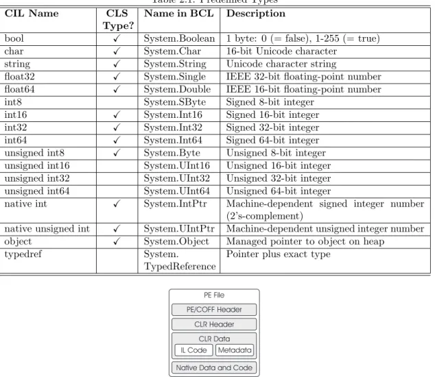
In Figure2.3a diagram containing the different value and reference types is presented. Here it is clear what the predefined value and reference types are and what kind of user-defined types can be created. What we omitted up to now is that it is also possible to create a reference type of a value type by a technique called boxing. For more information about boxing, we refer to [6]. The list of predefined types is shown in Table2.1. The table contains a description of the type, a mapping to the .NET class library and whether or not the type is supported by the CLS.
2.1.5
Portable Executables
CLR Type System
Figure 2.3: Types supported by the CLR
Table 2.1: Predefined Types
CIL Name CLS
Type?
Name in BCL Description
bool X System.Boolean 1 byte: 0 (= false), 1-255 (= true)
char X System.Char 16-bit Unicode character
string X System.String Unicode character string
float32 X System.Single IEEE 32-bit floating-point number
float64 X System.Double IEEE 16-bit floating-point number
int8 System.SByte Signed 8-bit integer int16 X System.Int16 Signed 16-bit integer
int32 X System.Int32 Signed 32-bit integer
int64 X System.Int64 Signed 64-bit integer
unsigned int8 X System.Byte Unsigned 8-bit integer
unsigned int16 System.UInt16 Unsigned 16-bit integer unsigned int32 System.UInt32 Unsigned 32-bit integer unsigned int64 System.UInt64 Unsigned 64-bit integer
native int X System.IntPtr Machine-dependent signed integer number
(2’s-complement)
native unsigned int X System.UIntPtr Machine-dependent unsigned integer number
object X System.Object Managed pointer to object on heap
typedref System.
(Portable Executable). A PE file is not executable by itself, it is the CLR that compiles PE files into native code. The layout of a typical .NET PE file is shown in Figure2.4.
The sections have the following meanings:
2.1 Overview of .NET 13
Graphical User Interface (GUI), Character-based User Interface (CUI) or Dynamic-Link Library (DLL). One of the components stored in the header is a timestamp indicating when the file was built. Furthermore, the PE/COFF header contains references to other contents within the PE file. For modules targeting the CLR there is information available allowing the runtime to seize control.
• The CLR header indicates that the PE file is a .NET executable. The most important components of the CLR header are the required version of the CLR, some flags, and possibly a description of the entry point method of the executable. The runtime header, which contains all of the runtime-specific data entries and other information, should reside in a read-only, shareable section of the image file.
• TheCLR data section containsmetadata and IL code. The metadata section contains two parts: tables that describe the types and members defined in the source code, and tables that describe the types and members referenced by the source code. The Intermediate Language code is created by the compiler that compiled the source language. This IL code will eventually be compiled into native machine code by the CLR.
• The Native Data and Code section contains native code, for example precompiled C++ to machine code.
Although the PE file contains different sections, we are only interested in the IL Code section. The IL Code section contains the IL program that is eventually simulated.
2.1.6
Virtual Execution System
In the CLR, program execution is performed by a number of components interoperating under the name Virtual Execution System (VES). The VES is also known as the Execution Engine. An overview of the VES is presented in Figure2.5. The VES is, among other things, responsible for loading a PE file (containing the IL program), the translation from IL into machine code, and for its execution.
.NET PE Files (Metadata and IL)
Class Loader
Verifier JIT Compiler
Execution Support and Management
Garbage collector, security engine, code manager, exception manager, thread support, etc.
JIT Compilation Virtual Execution Engine
Figure 2.5: Overview of the Virtual Execution System (VES)
2.1.7
Code Management
Stack and Heap
Astack is a data structure that works according theLast In First Out (LIFO) principle. Values can be respectively put on (pushed) and pulled from the top of the stack (popped). It is not possible to store or retrieve values of the stack, other than the top value. Additionally it is not possible to just read the top-of-stack value, without pulling it from the stack.
The Common Language Runtime is stack-based. This means that the CLR uses a stack to store intermediate values on. This stack is not addressable by other methods and is initially empty on each method call. On leaving a method, the stack only contains a return value (if available).
The heap is a dynamic storage area in which objects of classes and arrays can be stored. References to objects in the heap are stored by means of pointers on the stack. It is also possible that objects in the heap contain references to other objects.
An instance of a value type has its value stored on the stack (or in a containing object in the heap), meaning that a piece of memory is reserved for their value. Instances of reference types have a reference to heap-based objects allocated on the stack. Instances of reference types can be null.
Memory Management
When a method is called, amethod state(which contains the information captured in an invocation stack frame) is created. A method state contains all information about the environment within which a method executes. It contains an instruction pointer that points to the next IL instruction to be executed within the current method. It also contains an evaluation stack that is entirely local to the method, and thus cannot be accessed by other methods. The contents of the evaluation stack are preserved across call-instructions.
Both Input parameters (i. e. the arguments of the method) and local variables are stored in ordered lists that are addressable via an index. The values of both input parameters and local variables are preserved across method calls.
The local memory pool is used for dynamic allocation of storage space which is not freed by the garbage collector. The storage space will be reclaimed on method exit [19]. The local memory pool is used to allocate objects which type or size is not known at compile time and which the programmer does not wish to allocate in the managed heap [6].
Instr.
When a method is called, the new method state is appended to the end of a list of method states (method or procedure stack) and linked to its predecessor. The caller method is stored in thereturn-state handle. When returning to the caller method, the results of the method that is exited must be copied to the stack of the caller method and the method state must be removed from the list of method states because it is no longer needed. The return-state handle is used to restore the method state on return from the current method [6]. This corresponds with the
dynamic link compiler terminology.
2.1.8
Garbage Collection
2.2 The Intermediate Language 15
By default, garbage collection takes place when the system runs out of memory and no space is available to create new objects. At such a moment the garbage collector starts running. The garbage collector is responsible for suspending all active threads and marking all objects in the heap as garbage. After that, the garbage collector builds a graph for all objects reachable from the roots of the program. The roots of the program identify storage locations that refer to objects on the heap or to objects that are set to null. Once all roots have been checked (the graph contains only the objects reachable from the program’s roots), the objects not contained in the graph are considered garbage. The memory space used by these objects now can be freed and non-garbage objects are shifted down in memory to remove gaps in the heap. Because objects now are positioned on other memory addresses, the pointers to these objects now become invalid and must be updated by the garbage collector with the new memory address. Once these pointers are updated, the suspended threads can be restarted and the garbage collection phase is finished.
In Figure2.7an example of the heap before and after garbage collection is presented. The heap prior to garbage collection (Figure 2.7(a)) contains unreferenced objects (Object C and Object E), which are deleted during garbage collection resulting in the heap displayed in Figure2.7(b).
Object A
Figure 2.7: Example representation of the heap before and after garbage collection
The advantage of garbage collection is that objects are cleaned up automatically and thus do not have to be tidied up manually (which causes memory leaks when forgotten). The main disad-vantage of garbage collection is that it introduces a performance hit and also that the execution of all active threads must be suspended in order to apply garbage collection.
For more information about garbage collection we refer to [23,19].
2.2
The Intermediate Language
The .NET Framework uses language compilers that target the Common Language Runtime. For instance, Microsoft provides C#, J#, VB .Net, Jscript .Net, and C++ compilers. Furthermore, there are third-party compilers that target the CLR, such as an Eiffel, Cobol or Perl compiler.
As mentioned before, the source code of a .NET supported language is compiled to an inter-mediate format called the Interinter-mediate Language (IL). The IL includes instructions for loading, storing, initializing and calling methods on objects, as well as instructions for arithmetic and logical operations, control flow, direct memory access, exception handling and other operations [16].
2.2.1
Directives
Directives are bits of metadata representing the components which compose our program. They are are not actual IL instructions representing code [5]. Directives can ask the runtime-environment to perform some task and can be recognized in IL as productions starting with a period (.). For example, a method containing directive.maxstack n means that at mostn stack slots are required. For a complete list of directives we refer to the CLI Specification [6].
2.2.2
Modules and Assemblies
Modules are single files (PE-files, see Section 2.1.5) that contain executable code targeting the Virtual Execution System (VES). As stated above, a module contains type definitions and IL code.
One or more modules can be embedded in an assembly. An assembly is a logical unit of functionality, containing one or more modules. Thus, a .NET application can be packaged into assemblies, which respectively are called a single-file assembly and a multi-file assembly. The latter can also contain resources as images or sounds. In Figure 2.8 both a single-file assembly and a multi-file assembly are represented.
Figure 2.8: Difference between a single and multi-file assemblies and its modules
Note that the multi-file assembly contains multiple modules (which are physical files) and that one of these modules contains a manifest. The manifest contains information for finding all the definitions of an assembly, which is important for loading and running the other modules within the assembly. Also note that the multi-file assembly can contain images (fileimg.gif) and sounds (filesnd.wav).
To simplify this research project we only use single-file assemblies.
2.2.3
Namespaces
The namespace concept is used to group functionality within unique names. The name of the namespace is often the same as the name of the file in which the code exists, but it is also possible to have multiple namespaces in one single file or to have a namespace that spans over multiple files. To prevent equally named namespaces colliding with each other, they are contained within assemblies.
The Intermediate Language has no distinct concept ofcurrent namespace. A type is always referred to by its full name, relative to the assembly in which it is defined.
2.2.4
Methods
2.2 The Intermediate Language 17
methods or attributes. A static method thus is only associated with the type itself, instead of with an instance of that type. Static methods do not have an instance pointer (this). The arguments of static methods are indexed, starting with 0.
Instance methods are methods that are associated with an instance of a reference type, and can be virtual and nonvirtual. Virtual methods are those that can be replaced and overridden by subclasses, whereas nonvirtual methods cannot. Instance methods have access to thethis pointer as unlisted first argument at index 0, which they can use to access public, private and protected instance members of the enclosing type. When an instance method is called, the stack must contain the arguments preceded by the instance pointer.
A method is identified by its name, class type, and signature. When calling a static method, the type of the class is needed. And when calling an instance method, an instance of a class type needs to be provided. The signature exists of the return-type of the method, the number of arguments and the argument types. When a method is called, the CLR searches for a method containing the same name, type and signature as provided in the call. As soon as a matching method is found, the arguments (which should be placed on the stack prior to calling) are copied from the stack to an array that holds the passed arguments.If the initdirective is present, the local variables are initialized to the type’s default value. For example a variable of value type
int32is initialized to the value 0. If theinitdirective is not present, is deemed unverifiable in a security check performed by the CLR [15]. After initialization of the local variables, the method’s evaluation stack is empty and the execution of the first instruction can start.
When the method reaches the last instruction, which is theretstatement, the return value (if available) needs to be on the evaluation stack, and the method state transfers control to its caller.
2.2.5
The IL Instruction Set
The IL instruction set provided in Partition III of the CLI Specification [6] is partitioned into two sections, called base instructions (e. g. addition and subtraction) and object model instructions. There are over 220 instructions. A full documentation of the IL instruction set can be found in the CLI specification [6].
Most IL instructions perform their actions by using the evaluation stack that is associated to each method state (see Figure2.6). For example an add expression that adds two valuesvalue1
andvalue2 yields aresult. What happens in IL is represented in Figure2.9. The two values are pushed on the stack by using theldcinstruction. Subsequently an arithmetic operation (add) is executed, which pops the two values from the stack and replaces them with the resulting value. Note thatvalue1,value2, andresult represent actual values.
value2
Figure 2.9: Execution of instructions on the stack
The .NET Intermediate Language contains instructions that are completely independent of the type of their arguments [19]. For example, it is possible to use the same instruction to load a value of a local variable on the stack for both an integer and a floating-point number. The reason for this design decision is that Microsoft wanted the creation of source-to-IL compilers to be as easy as possible, in order to extend multi-language support.
Sometimes IL instructions are used with an efficient encoding. For example, for loading an argument onto the stack, it is possible to either use the instructionldarg <num> (for which an
int16 number represents the index), or the instructionsldarg.0,ldarg.1,ldarg.2andldarg.3
the instruction. Furthermore, the CLR does not need to read the instruction argument, resulting in some performance gain. For indices 4 to 255 it is also possible to useldarg.sfollowed by an
int8 number representing the index, which is called a short form.
The IL instruction set can be categorized further than the previously mentioned categories base instructions and object model instructions, as presented in the following sections. For a full and detailed list of instructions, we refer to [6].
Load and store instructions
These are instructions used to load values or references onto the stack and retrieve them from the stack to store them at their home locations. Typical examples of such instructions areldarg,
ldloc,ldobjand their counterpart instructions, beingstarg,stlocandstobj.
Arithmetical, logical and type conversion instructions
To be able to support arithmetical operations, IL contains typical arithmetic instructions such as
add,sub,mulanddiv. IL also supports logical instructions (called bitwise instructions in the IL specification[6]) likenot,andandor. An example of a type conversion instruction isconv, which is available to convert the value on top of the stack to the specified type.
Branching instructions
In IL there are a number of instructions that are used to control the flow of execution. We distin-guish conditional and unconditional branch instructions. Conditional branch instructions either take one value from the stack (and check whether a condition specified by the used instruction is true) or they compare two values on the stack. Depending on the outcome of the condition a branch follows. For example, the instructionbrfalseadjusts the control flow if the value on the stack isfalse. Another example is the instructionbeqwhich stands for ‘branch on equal’. In this case the control flow is adjusted to a target if the top two values on the stack are equal. In both cases, the program does not branch and continues executing the next instruction if the condition is not satisfied.
Unconditional instructions are instructions that do not depend on a condition. An example of such an instruction isbr, that unconditionally branches to a specified target.
Miscellaneous instructions
Beside previously mentioned instruction types, IL also contains instructions like calls and a return instruction.
There are different types of call instructions in the IL.callis used for calls to static methods of which the destination is fixed at compile-time, whilecallvirtuses the class of an object (known at runtime) to determine the method to be called. The callvirt instruction is used for both instance methods.
The return instructionret, which is used to return from a method, is performed without any condition. The value that is on the evaluation stack, if there is any, is copied to the evaluation stack of the caller and control is transferred to the caller.
2.2.6
Generics
Generics allows defining a class or method without a specific type. The defined item can then be reused with several types. Generics provides type safety at compile-time.
2.3 Our Work 19
2.2.7
Name Resolution
Names in the IL exist of a simple name or of a composition of simple names with connection symbols such as a dot. For example,SystemandObjectare simple names, whileSystem.Object
is a composite name. A composite name is also called adotted name.
The common prefixes offull class names are callednamespaces. The full name of a class is a dotted name. The last simple name of the dotted name is the class name. For example the dotted nameSystem.Object. HereObjectis the class name andSystemis the namespace.
[Mscorlib]System.Object::ToString()
Figure 2.10: A method call, referenced by its assembly and dotted name.
A class is scoped to a particular namespace, and a namespace is scoped to the provided assembly. If no assembly is provided, the namespace is scoped to the current assembly.
2.3
Our Work
In the rest of this report – especially in Chapter 4 and Chapter5 – we treat the .NET concepts that we have implemented. These cover the implementation of a stack representation, support for integer types and object types, and the ability to instantiate objects and call both static and instance methods. The instructions we treat are involved with arithmetical operations as well as instructions that do comparing and branching. We also implemented support for instructions that are used to explicitly load and store values from and to arguments, fields, locals, and the stack.
2.4
Summary
In this chapter we have introduced the Microsoft .NET Framework. We have recalled what Mi-crosoft’s objectives are for developing the .NET Framework, and which components the framework consists of. We have explained that the Common Language Runtime is the environment in which .NET applications are executed. It uses IL code as input and compiles this to native code, prior to executing it. This process is called JIT compiling. Besides the execution of IL by the CLR, we have introduced the Common Type System and Common Language Specification.
Furthermore, we told something about how IL is stored in a binary format in a so-called Portable Executable file. This file is loaded by the Virtual Execution System, which is part of the CLR. We also have introduced some aspects of code management, which covers the usage of a stack and heap. The stack is used by the CLR to store intermediate values and references on. The heap is a dynamic storage area in which objects of classes and arrays can be stored. When executing a program, each method gets a method state assigned. A message state contains information about the environment within which the method executes, like an instruction pointer and lists of input arguments and local variables.
The Intermediate Language was also introduced in this chapter. We have told something about directives, which are commands that ask the runtime-environment to perform a task, as well as about modules and assemblies. Modules are physical files that can be embedded in an assembly, which is a logical unit of functionality. The IL also uses namespaces, which can be used to group functionality within unique names. We also mentioned methods, which are operations associated with a type, and what happens when they are called. There are two type of methods, namely instance methods and static methods.
Chapter 3
Graphs and Graph
Transformations
Graphical structures like charts and diagrams, are often used to represent complex data and structures in an intuitive way. A graph is such a graphical structure, and is applied in different areas like route planners, electric circuits, job scheduling and train-networks.
Groningen
Figure 3.1: A graph representation example
Figure3.1is an example of a graph. It represents a number of road connections between cities in The Netherlands, the nodes representing cities and the edges being the roads. The cities contain labels with the name of the city. In this example we omitted the labels on the edges. However, edges could be labelled with names (of the roads) or values (representing distance, fuel usage, travel time, travel expenses, etcetera).
Throughout this chapter we use Pacman examples to explain different concepts. These exam-ples are based on the examexam-ples presented in [8].
3.1
Graphs
A graph is a mathematical structure. We use edge-labelled graphs defined over a setLabof labels, as follows [12]:
Definition 3.1 (Graph). A graphGis a tuplehN od, Edgiwhere
• Nod is a finite set of nodes;
• Edg⊆Nod×Lab×Nod is a (finite) set of edges.
The graphs we use are directed graphs, i. e. for each edge we distinguish between itssourceand
target node. Furthermore, as follows from the definition, edges have a label and nodes can not. It is possible to create an edge with the same source and target node, i. e. self-edges of a node. Self-edges can be considered as a way of labelling nodes. A node can have multiple self-edges and thus multiple labels. In this setting, it is not possible to have more than one edge with the same source, target and label, i. e. parallel edges.
3.1.1
The Pacman Example
An example graph, bases on the Pacman game, is given in Figure3.2. In the graph a number of nodes are shown, namely the dots, and the figures of Pacman, the ghost and the apple. The grid of dots and the edges between them represent the fields to which Pacman, the ghost and the apple are bound. The normal behaviour would permit both Pacman and the ghost to be able to move over the grid. To keep this example simple, we assume the ghosts to be fixed to a specific node in the grid. For simplicity, we also omitted the labels on the edges.
Figure 3.2: Graph representation of Pacman
3.2
Graph Production Rules
To transform a graph (source graph) into another graph (target graph), we use graph transforma-tion rules. Graph transformatransforma-tion rules are also calledgraph production rules.
A graph production rulephas the form p: L→R, in whichLrepresents the left hand side (LHS) graph andRthe right hand side (RHS) graph.
3.2 Graph Production Rules 23
L by R, leading to the target graph of the graph transformation[7, 8]. This replacement is not complete, because the structure is preserved wherever theLandR overlap[13].
Application of a production rule can be written asGp,m→ H, meaning that graphG is trans-formed into graphH by using production rulepat matchingm. It is possible thatphas multiple matchings of its LHS in graphG, but also that multiple rules are applicable to the same graph.
Production rules can be extended with negative application conditions (NACs, see [7,10]). A negative application condition limits the applicability of a rule by extending the rule’s LHS. A rule pwill only be applied to a source graph Gwhen the LHS matchesG and if that matching cannot be extended to a matching of any NAC of that rule.
3.2.1
The Pacman Example - Production rules
An example of a production rule in the context of the Pacman game is presented in Figure3.3. According to this rule, calledmove, Pacman moves to a new position by removing the edge between Pacman and a noden(e. g. the left node in the rule below), and placing an arrow between Pacman and the neighbour node ofn.
move
Figure 3.3: Production rule to move Pacman
Of course it is also possible to simulate the behaviour of a ghost eating Pacman, or Pacman eating an apple. See for example, Figure3.4.
kill kill
(a) Rule of Ghost killing Pacman
eat
(b) Rule of Pacman eating an apple
Figure 3.4: Two additional production rules
In Figure3.5 the application of a production rule is displayed. For this example, we use the already introduced production rule for moving Pacman and the graph representing Pacman and the grid of nodes. (For space reduction, we have presented only a part of this graph.)
In this example, we have a production rulepconsisting of left hand sideL and a right hand sideRand a transition betweenLandR. There is a matchingmbetweenLand the source graph G. This is indicated with the dashed and dotted arrows. Now that there is a matching m of rule p, it is allowed to transform graph Gby replacing the matched nodes of L by the nodes of R, resulting in a graphH. Note that the arrow in graphG, denoting the position of Pacman, is deleted and that in graphH a new arrow is constructed. Thus, Pacman has been moved from one position to another.
As mentioned before, production rules can be extended with NACs. In Figure3.6we extended the previously introduced rule to move Pacman from one node to another (see Figure3.3) with a NAC. In this example, Pacman may only move to a node when there is not a ghost positioned at that same node.
GraphG GraphH
Figure 3.5: Example application of production rule
move
Figure 3.6: Production rule to move Pacman, containing Negative Application Condition
the case, the NACs are satisfied and the rule can be applied by replacing the matched elements of the LHS by the elements of the RHS of the rule.
3.3
Graph Production System
Agraph production system (GPS) consists of a set of graph production rulesRand a start graph I. The GPS can be used to generate a (possibly infinite) state space by applying production rules p∈ R to the graphs, starting with graphI. All the resulting graphs can be seen as state snapshots (states), and the application of the rules as transitions between the states. The set of graphs and transitions between these graphs, we call agraph transition system (see also [14]). A graph transition system always contains an initial state. Furthermore, it can have intermediate states and a final state if the state space is finite.
3.3.1
The Pacman Example - Graph Transition System
In the context of the previously introduced Pacman example, we present an explanation of a graph transition system. For this example, we have taken the graph presented in Figure 3.2 as start graph. When applying the rules from Figure 3.3 (move) and Figure 3.4 (kill and eat) whenever possible, we get the graph transition system displayed in Figure3.7.
3.4 Graph Transformation Tool 25
Figure 3.7: Transition system of Pacman example
3.4
Graph Transformation Tool
The tool we use for performing graph transformation is GROOVE [22]. GROOVE stands for GRaphs for Object-Oriented VErification. With this tool it is possible to specify graphs and production rules. It can also execute these production rules, which results in a graph transition system.
In GROOVE, graphs are represented by blocks for nodes and arrows for edges. Self-edges are represented as an arrow with the same start and end node, or as a label on a node (inside the rectangle).
Furthermore, GROOVE offers the LHS, RHS, and the NACs of a production rule to be rep-resented in a single graph. To accomplish this, the production rules used by GROOVE consist of four different types of nodes and edges, each having different shapes and colours [21, 13]:
• reader-elements are elements that occur in both LHS and RHS. They have to be present in the source graph to match the LHS and are preserved in the target graph. Reader-elements are represented by thin solid black arrows and rectangles.
• eraser-elements are elements that occur in the LHS but not in the RHS. They have to be present in the source graph to match the LHS, but are deleted in the target graph. Eraser-elements are represented by thin dashed blue arrows and rectangles.
• creator-elements are elements that do not occur in the LHS but do occur in the RHS. They have to be absent in the source graph in order to be introduced in the target graph. Creator-elements are represented by thick solid green arrows and rectangles.
• embargo-elements are elements that prohibit the application of the rule when they exist in the relating matching in G. Embargo-elements are making up the NACs and are represented by thick red dashed arrows and rectangles.
3.4.1
The Pacman Example - GROOVE
Figure 3.8: Example production rule in Groove
3.5
Summary
This chapter introduced the concepts of graphs and graph transformations. We have told that our graphs contains nodes and labelled edges. Furthermore, we have mentioned that it is not possible to have parallel edges. A (source) graph can be transformed into another graph (the target graph) by using graph production rules. A graph production rule can be applied to a source graph when the left hand side of the production rule has a matching in the source graph, but only when negative application condition are satisfied.
Furthermore, we have provided a brief description of the graphical notation of graph transfor-mations in the GROOVE tool set. There, we distinguish four types of nodes and edges, namely: reader, eraser, creator, and embargo elements.
Chapter 4
Translating IL Programs to
Graphs
Before introducing the developed graph production rules in the next chapter, we focus on the start graph to which the graph production rules are applied. This start graph is an abstract model of the IL program to be simulated. Because the .NET language compilers generate IL bytecode, and the GROOVE tool set needs a graph as input, a translator is developed that translates arbitrary IL programs into a graph representation of that program. Such a graph is called an Abstract Syntax Graph (ASG).
This chapter starts with a description of the translator. We will introduce the structure of the translator, what its input is and which operations are performed on this input. In Section4.2 a meta-model of the ASG is shown and discussed.
In Section 4.3, we propose a representation for namespaces. We also discuss how method signatures are calculated, how they are represented in the graph, and how existing method signa-tures are resolved. Additionally, Section4.3 contains a description of the static analysis process performed by the translator.
After discussing static analysis, we present an example in which we translate two equivalent programs written in different .NET languages (i. e. C# and VB.NET) to the .NET IL. In this example, we will show that both programs will result in two IL programs having comparable semantics. Furthermore, we will provide an example of the translation of an IL program to an ASG.
4.1
Translator
The translator uses a textual IL program as input. This textual IL program is obtained by disassembling a Portable Executable file (see Section2.1.5), using the disassembler calledildasm. The toolildasmis incorporated in the .NET Framework SDK 2.0, which is freely available from the Microsoft website1
. Because we are disassembling a program that has already been type checked by the compiler that created the PE file, we can assume that the program is type correct. Note that this only applies to type errors detectable at compile-time and not at run-time (such as explicit type casting of objects). Because we assume that programs are correctly typed, we do not perform any type checking in neither the translator nor the production rules.
During the translation phase, a textual IL program is read and transformed into a graph representation of this program. To do this, we could implement our own translator from scratch or use a compiler generation tool that creates one for us. Implementing a translator from scratch would involve a lot of work. Therefore we have chosen to use a compiler generator tool called ANTLR[2]. ANTLR uses grammar specifications as input and automatically generates a translator
1
according to this specification. We obtained a grammar for a .NET Intermediate Languageparser
(written by Pascal Lacroix) from the ANTLR website, which had to be modified due to non-determinism. The grammar file for the tree walker is our own implementation. The generated translator consists of alexer, aparser, and atree walker.
Lexer The lexer scans the input file (i. e. an IL program) and chops it into pieces called tokens. These tokens are sequenced into a stream – called a tokenstream – and sent to the parser.
Parser The tokenstream is used as input for the parser which creates an Abstract Syntax Tree (AST). An Abstract Syntax Tree is a tree-shaped abstract representation of the program. The AST can be used to transform and order program information. Furthermore, it is used to omit syntactic information from the original program without losing its semantics. This makes it easier to process it further by the tree walker.
Tree walker A tree walker is used to visit all nodes in the AST and to create a new structure in the form of an Abstract Syntax Graph.
An overview of the translation process is presented in Figure4.1. The rectangles represent the input and output of the different parts of the translator. The labels on the edges denote the parts of the translator that are responsible for translating an input into an output.
Textual
Figure 4.1: Overview of the translator
The result of the translator, the Abstract Syntax Graph, is used as GROOVE’s start graph for simulation using graph transformations. This is explained in Chapter5.
4.2
Meta-Model Abstract Syntax Graph
In order to formalize and give an overview of the structure of the ASG, a meta-model has been designed. Because this meta-model is too large to fit in one figure, it is spread over multiple figures, which are Figure4.2to Figure 4.5. Together, these figures describe the concepts that are used in the ASG, and the relations between these concepts.
4.2.1
High-level structure
4.2 Meta-Model Abstract Syntax Graph 29
Figure 4.2: Meta-model of the Abstract Syntax Graph
The rest of this section contains a description of the concepts presented in the meta-model presented in Figure4.2. Note that this contains twoIdentifiernodes. BothIdentifiernodes represent the same concept of an identifier and were put in the model for preventing too many crossing lines.
Program TheProgramconcept is the root of the graph and represents a parsed IL program. A
Programcan containNamespaces,Types andAssemblys.
Namespace ANamespacerepresents the logical grouping of the names used within a program. They can be nested in an IL program, but we choose to represent this in a non-nested man-ner, because classes are always referenced by its fully qualified name. For more information see Section4.3.1. ANamespacecan containTypes, in the form ofClasses.
Assembly TheAssemblyconcept represents a logical unit that can holdClasses andNamespaces. Furthermore, an Assemblyis identified by a nameand can have Attributes. We use the Assembly
concept (at this moment) only to determine whether or not classes from the .NET Class Library are called.
Type TheTypeconcept represents types like classes and value types. See Section4.2.2for more information.
Class TheClassconcept is a subtype of theTypeconcept and represents a class declaration. A
Classcan extend another Class, has a name (which is identified by its Identifier) and can contain
Signature The Signature node is used to represent method signatures. A method signature contains the method’s return type, the calling convention, and the method’s parameter types in an ordered way. The signature is determined by the parser; how this is done will be explained in Section4.3.2.
Method TheMethodnode represents a method declaration. A method declaration always has
aSignature and must have aMethodBody.
MethodBody MethodBodyrepresents the method’s implementation.
Instruction Instructions are denoted by the Instruction concept. Section 4.2.4 discusses the individual instructions.
Identifier TheIdentifiernode represents a name that is used to name an element.
CallConv CallConv represents the calling convention of a method. The calling convention de-notes whether or not the call is to a static method.
Parameter The Parameter concept represents a formal parameter in a method signature and describes variables which are accepted by a method. Parameters are of a certainType, may have aname (identified by theIdentifierconcept), and are contained in the methodSignature.
Field The Field node represents the declaration of a field. A Field has a name (identified by
Identifier), attributes (denoted byAttribute), and has atyperelationship to theTypeto denote its type.
Local TheLocalconcept represents the declaration of a local variable. ALocalcan have aname
(identified byIdentifier), and has a relationship to theTypeto denote its type.
Init The Initconcept is used to denote that the Local variables of a MethodBody must be ini-tialized to their default values.
Attribute TheAttributeconcept represents available attributes. It is further explained in Sec-tion4.2.3.
Entrypoint Theentrypointconcept denotes the start point of executing aProgram.
4.2.2
Types
This meta-model (see Figure4.3) describes the types that are available in the ASG. The following types are supported in our ASG and production rules.
bool Theboolconcept represents the type bool (i. e. boolean) of which the values can be either a true (non-zero) or false (zero).
char A value of typechar can hold a single Unicode character.
4.2 Meta-Model Abstract Syntax Graph 31
Figure 4.3: The types in the ASG meta-model.
float32, float64 The conceptsfloat32andfloat64represent floating-point types (which describe floating-point values). Note that this concept is not used (yet), because GROOVE does not support floating point values.
int8, int16, int32, int64 These nodes represent integer types of different sizes (respectively 1, 2, 4, and 8 bytes). We do not distinguish between these types during run-time simulation using production rules, because we do not have a notion of memory-sizes.
void The concept voidis only used as a return type, indicating that a method does not return a value.
Class The Classnode represents a class type which can contain Fields and Methods. See Fig-ure4.2.
4.2.3
Attributes
The meta-model presented in Figure4.4contains a description of the different kinds of attributes available. These attributes are at this moment not used in the production rules, but we have put them in the graph for possible future extension.
Attribute
ImplAttribute MethodAttribute ClassAttribute AssemblyAttribute
ParamAttribute FieldAttribute
Figure 4.4: The attributes in the ASG meta-model.
Examples of well known attributes areprivate,public, static, andabstract. For all the different types of attributes, we refer to the ECMA specification [6].
4.2.4
Instructions
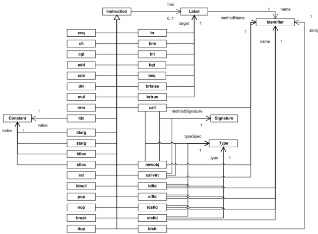
The instructions denoted by this meta-model are the .NET IL instructions that a method body can hold. The instructions we support are given in Figure4.5.
Label
Figure 4.5: The instructions in the ASG meta-model.
Instruction See Section4.2.1.
Label TheLabelconcept denotes a label that is used to tag an instruction, which can be used as a target to branch to. In this project a label always is represented by anIdentifier.
ceq, clt, cgt Theceq,clt, andcgtinstructions stand for compare if equal, less than, and greater than. When executing these instructions, two values on the stack are popped, compared, and the result of this evaluation is pushed back on the stack. The result is 1 (of type integer) if the evaluation yields true, otherwise 0.
add, sub, div, mul, rem These arithmetical nodes represent arithmetic instructions, namely addition, subtraction, division, multiplication and remainder (modulo).
ldc The instructionldcloads aConstantvalue on the stack.
call, callvirt, newobj The concepts call and callvirt represent static and dynamic calls, re-spectively. The instructionnewobjrepresents the creation of a new object. All three instructions are related to the Signature node, representing the signature of the method to call. In case of
the newobjinstruction this is the constructor’s Signature. Furthermore, the instructions use an
Identifier representing the name of the method to call. Also, they are related to a type which
4.3 Design Decisions 33
ret Theret instruction is used to return from a method to its caller. In this project we assume that a method is always ended with aretinstruction. In IL there are other possibilities to terminate a method, i. e. withthroworjmp, but these are not supported yet.
ldfld, stfld Theldfldinstruction is used to load a value from an instance field to the stack, and thestfldinstruction is used to store a value from the stack to an instance field. Both theldfldand
stfldinstructions use an edge with labeltypeSpecto refer to the type of the instance of which the field that the value that is loaded or stored is an instance. Thenameedge points to an identifier representing the name of the field. Furthermore, the instructions have an edge called type to a specificTypeto indicate the type of the field.
ldarg, starg The instructions ldargandstargare used to load the value of an argument on the stack and store a value from the stack to an argument, respectively. The argument is indicated
by aConstantvalue representing theindexof the argument.
ldloc, stloc Theldlocandstloginstructions are used to load a value from the stack to a local variable, and vice versa. The used local variable is indicated by its Constant value representing
theindex. ThetypeSpecedge indicates the type of which the object is an instance of. The name
of the field is referred to by anIdentifier node.
br, bne, blt, bgt, beq, brfalse, brtrue These instructions represent branch operations. The instruction br represents an unconditional branch to an instruction bound to a specific
Labelrepresenting its target. The other instructions depend on the evaluation of a condition.
If the evaluation yieldstrue, then the control should branch to the target-instruction represented by theLabel. Otherwise, the control is transferred to thenextinstruction.
Type See Section4.2.2.
Identifier See Section4.2.1.
Signature TheSignatureconcept represents a method signature and is used to locate a method implementation.
Constant TheConstant concept stands for GROOVE’s way of representing an actual value of a specific type, which can only be integer, boolean or string.
4.3
Design Decisions
Implementing the translator came along with a number of problems. Decisions about the rep-resentation of namespaces, classnames, signatures and identifiers had to be made. These design decisions are discussed in this section.
4.3.1
Classnames and namespaces
In the IL it is possible to have nested namespaces, which we will explain on the basis of the example code of Listing4.1. We have left out the details in this pseudo code in order to emphasise the namespace structure.
The example shows that it is possible to have a namespace A.B, which stands for a nested namespaceB in namespace A. Furthermore, a namespaceEis nested in a namespace Dto create the nested namespaceD.E. Also, classes can be declared in a namespace. Classes X,Y, and Zin the example are declared in the namespacesDandD.F, respectively.
1 . namespace A {
A useful namespace representation in the ASG is needed in order to use namespaces in pro-duction rules. Therefore, we propose three alternatives.
Alternative I. Nested namespaces (Figure 4.6(a))
4.3 Design Decisions 35
resolve a nested namespace by its full name. For example, in this representation resolving the namespaceA.Bby using production rules would involve multiple production rules to resolve each (sub)namespace.
Alternative II. Flat nested namespaces (Figure 4.6(b))
This representation also uses a nested structure of namespace nodes, but this time with dotted name. This has as advantage that it preserves the nested structure, and that it is possible to resolve namespaces directly by their full name. For example, in Listing4.1we declare a namespaceG.H.I, without using the namespacesGandG.H.
Alternative III. Flat namespaces (Figure 4.6(c))
This representation uses dotted names for the namespaces, and relates them directly to theProgram
node. Thus, nesting information is not explicitly available. This is not a problem because in IL no relative names are used without using a fully qualified name. This representation is easier to implement, because every namespace node can simply be attached to the Program node.
B C E F
(c) Dotted namespaces, attached toProgram
Figure 4.6: Namespace representation proposals.
We have chosen for the third alternative and will represent namespaces in the ASG by using dotted names, attached to the Program node. To get this result in the ASG for an arbitrary program, the translator must transform the namespaces and classes to this representation into full names (in case these names are not already in this representation).
Transforming the code of Listing4.1, results in the graph represented in Figure4.7. Note that this still is a stripped down graph, merely to explain what the namespace structure looks like.
Figure 4.7: ASG of Listing 4.1.
What we did not mention up to now is that classnames and namespaces are stored in the Abstract Syntax Tree in order to be able to create method signatures (as described in the next section). Method signatures are used for resolving method calls during the simulation phase.
4.3.2
Method signatures
A signature of a method is defined by its calling convention, its return type, and the number, order, and types of the parameters. Note that a method signature in IL does not contain the name of the method. This is for example in contrast to Java, where the signature contains the name of the method along with the number and types of the parameters (and their order). Methods are compatible when they share the same signature. But when a method is called, the method lookup is performed by using the method name combined with the corresponding signature as specified in the call.
Our solution is to create unique method signature nodes, and references to these nodes, by the translator. After determining the signature, a lookup is performed on a set containing references to existing signatures. If the signature already exists, an edge is created to the node representing this signature. If the signature does not exist, we create the nodes representing the signature, store it in the set of signatures, and create an edge to the node representing the signature.
4.4 Translating C# and VB.NET to IL 37
Figure4.8contains an example of how signatures look like and how they are referred by method calls. The class, namedCallExample, contains a method with the nameprint. For this method, a signature is created withvoidas return type. Furthermore, the signature shows that the method
print accepts a string as parameter. The figure also contains a call instruction that calls the method printof class CallExample with a specific signature, namely the method with return typevoidand a parameter of typestring. Now that the signatures are resolved, it is possible to find the correct method implementation during simulation.
4.3.3
Identifiers
Identifiers values, such as names, are represented by one node for each unique denotation. Thus when two labels have the same name, this is represented by two label nodes both pointing to one single node with the identifier name as its label. This is accomplished by generating a key from the identifier name and determining if, according to this key, the identifier is already known. If it is unknown, the node representing the identifier is created. Otherwise the existing node is used.
For example, instructions can contain labels (which are equivalent to identifiers) and can target to labels. When these labels have the same name, they must point to the same node (see Figure4.9).
Figure 4.9: Relation of labels to identifiers
The idea of this representation is that in the code of the program physically two labels are present, but they both contain the same name. Thus, in our representation we use two label nodes, but only one single name node. During static analysis with production rules, these labels are resolved. Off course, it is possible to identify the labels (instead of their identifiers) in the translator, but we have chosen to use graph production rules in order to provide more intuition in what happens during this process.
4.4
Translating C# and VB.NET to IL
In the introduction we claimed that when we cover semantics of the IL instructions, it should be possible to simulate programs written in every .NET language. To support this idea, we have written two simple programs. The first is written in C#, the second in VB.NET. Both programs were compiled to an executable and disassembled. For the C# program, we used the following command line options:
csc /t:exe /optimize+ program_name.cs
ildasm /text /out=program_name_cs.il program_name.exe
And for the VB.NET program we used:
vbc /t:exe /optimize+ program_name.vb
We expect to get two IL files having comparable semantics, but with slightly differences in the used instructions. The C# and VB.NET programs that we have used as input are shown in Listing 4.2 and Listing 4.3. Because the output of the created IL code is relative large, two excerpts are provided that are used to compare with each other. For the interested reader we disposed the IL code of the metadata and provided the methods in AppendixA.
1 class Example {
10 public static void Main () { 11 theResult = Fibonacci (4) ; 12 }
13 }
Listing 4.2: Fibonacci Example in C#
1 Module Example
2 Dim theResult As Integer
3 Function Fibonacci ( ByVal x As Integer ) As Integer 4 If ( x = 0 Or x = 1) Then
Listing 4.3: Fibonacci Example in VB.Net
In this example we use the series of Fibonacci2
. From the generated IL code, we can see that the body of both the Fibonacci instructions are identical to a large extent. There are a few differences that depend on the used compiler. One difference is for example the usage of different comparison strategies for the evaluation part in the if-statement of the body of the Fibonacci
method. Theif-statement in line 4 of Listing4.2is compiled to the code presented in Listing4.4, while theif-statement in line 4 of Listing4.3is compiled to the IL code presented in Listing4.5. The C# compiler generates IL code that is slightly more optimized than the IL code generated by the VB.NET code.
Although we mentioned that different .NET languages are compilable to IL, we must emphasise that for this research project only C# programs were compiled and disassembled to IL.
2
Thenth
number of Fibonacci is calculated according to: F ib(0) = 0
F ib(1) = 1
4.5 Example: IL to ASG 39
Listing 4.4: IL excerpt obtained from C# compiler
11 IL_0000 : ldarg .0 // Load x 18 IL_0009 : brfalse . s IL_000d
19
20 IL_000b : ldarg .0
21 IL_000c : ret
Listing 4.5: IL Excerpt obtained from VB.NET compiler
4.5
Example: IL to ASG
Now that we explained what an ASG is, how it looks like (using a meta-model), and what our translator does, we present an example of translating an IL program to an Abstract Syntax Graph. We have taken the IL program presented in Listing A.3 of Appendix A. Translation of this IL code yields the Abstract Syntax Graph presented in Figure4.10.
In general cases, we are not interested in the entire ASG but in particular in the simulation results. That is, the executed production rules (presented in the LTS) and the simulation elements of the generated graphs. This is the topic in the next chapter.
4.6
Summary
This chapter started with an introduction of the translator that is implemented to generate an Ab-stract Syntax Graph from arbitrary IL programs. We have described the different parts (i. e. lexer, parser, and tree walker) of the translator and their purpose. Furthermore, a description of the ASG is presented in the form of meta-models. All nodes and their relationships to other nodes are described.
Also, the design and representation decisions are presented in this chapter. These are decisions with respect to the representation of classnames and namespaces, calculation and representation of method signatures, and representation of identifiers.
Chapter 5
Specifying IL Semantics with
Graph Transformations
This chapter describes how we use graph transformations (explained in Chapter3) to specify the IL semantics. In order to be able to perform graph transformations, we need a start graph. This graph is generated by the translator described in Chapter 4 and is the Abstract Syntax Graph (ASG) of an arbitrary IL program.
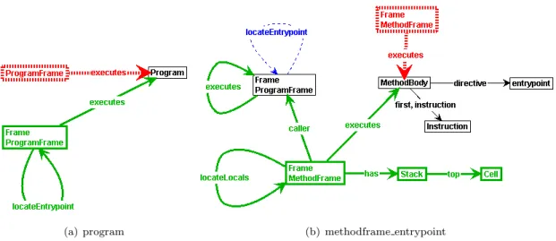
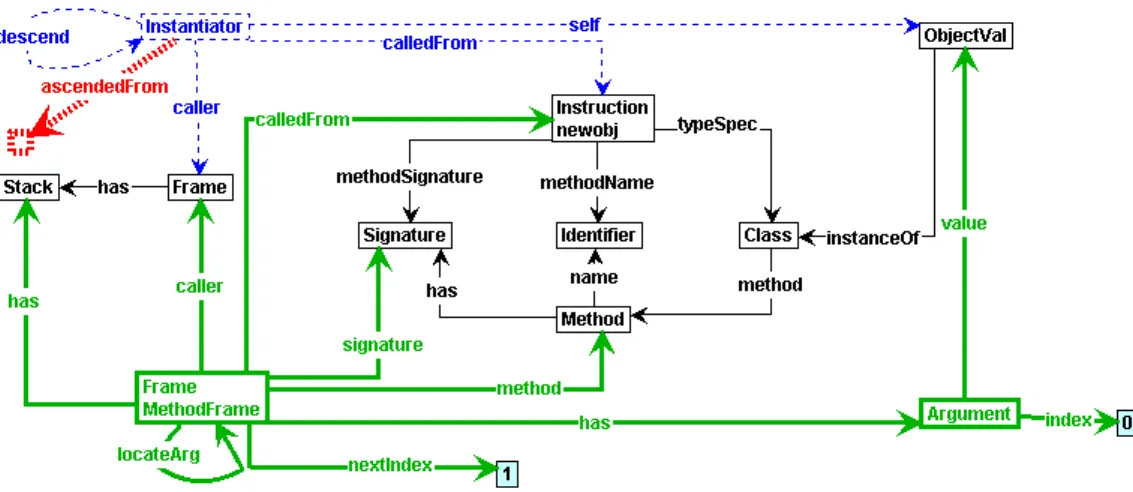
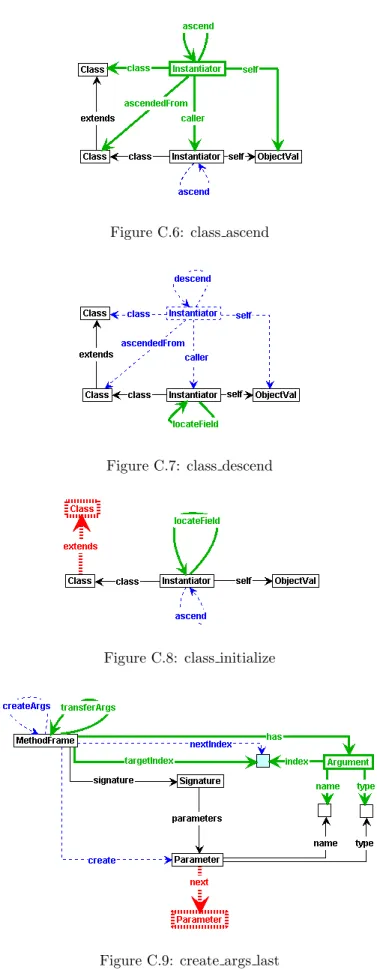
We start this chapter by describing how static analysis is performed by using graph production rules. Furthermore, the ASG implicitly contains control flow information. This control flow information can be made explicit by performing control flow analysis. Then, production rules for control flow analysis should enrich the graph with specific control flow nodes and edges. The decision whether or not to make this control flow information explicit is discussed in Section5.2. Section5.3 introduces what we call the Frame Graph (FG). The FG is used to decorate the start graph with runtime concepts for being able to simulate the execution of a program. In this section we provide a meta-model to describe the FG and discuss implementation alternatives and decisions for some of the concepts present in the Frame Graph. In this section we also describe the Value Graph (VG). The VG describes the relation between the Frame Graph and values.
The production rules describing the semantics for IL instructions are presented in Section5.4. In general, we use one or two production rules for each instruction. However, this is not always possible because some instructions start a sequence of actions which must be put into effect.
Then, having production rules describing the semantics of a number of IL instructions, it is possible to simulate a program using the GROOVE Simulator. In Section5.5 we will show this by simulating two example programs.
5.1
Static Analysis
In Chapter 4 we explained
![Figure 2.2: Common Type System and Common Language Specification For more information about the CTS and the CLS, see [ 6 ].](https://thumb-us.123doks.com/thumbv2/123dok_us/1040713.1129729/13.892.354.548.332.525/figure-common-type-common-language-specification-information-cts.webp)