COMPACT LOWPASS FILTER WITH SHARP TRANSI-TION BAND BASED ON DEFECTED GROUND STRUC-TURES
A. S. Mohra
Electrical Engineering Department College of Engineering
King Saud University
P. O. Box 800, Riyadh 11421, Saudi Arabia
Abstract—A lowpass filter with a very sharp transition band using defected ground structures (DGS) is described. The lowpass filter was designed by using three dumbbell slots at the ground plane. Two of those dumbbell slots are the reshaped rectangular and the third dumbbell slot is an inverted triangle. The lowpass filter designed at cutoff frequency of 3.0 GHz, which is suitable for GSM900, GSM1800 and UMTS applications of the mobile communications. The equivalent circuits for the proposed lowpass filter and its corresponding LC parameters are given. The proposed lowpass filter provides a size of 33×30 mm2, and have good transition band with good performance in the passband and have wide rejection up to 9.25 GHz plus harmonic suppression in the stopband. Measurements results show good agreements with the simulated results.
1. INTRODUCTION
Microstrip filters are essential components in modern microwave com-munication systems, especially in satellite and mobile comcom-munications. With the current expansion of the wireless communication industry, the requirement of high performance filters is increasing. In recent researches, the compact size and harmonic suppression for the low-pass filter structures are two important factors in their design. Com-pact structures at high frequencies should show good performance, large reject band between the first and the second harmonics and a good suppress of secondary harmonics. There are different features of
the microstrip lowpass filters to improve; first, to get very sharp cut-off frequency response and low ripple corresponding to return loss in the passband; second, to get wide stopband characteristic and good stopband rejection; third, to have small and compact size. Most of these features can be achieved by using the defected ground structures (DGS). A defected for the microstrip line circuit is the etching in the backside metallic ground plane, that disturbs the current distribution in the ground plane, and increases the effective inductance and capac-itance of the microstrip line. The microstrip line with defected ground structure pattern provides bandgap effect at certain frequency [1–3]. Therefore, the DGS is usually modeled by LC resonance circuit by using a circuit analysis method. An equivalent circuit of parallel LC circuit corresponds to this bandgap effect can be used in filter design. Various shapes of DGS have been investigated in [1–11]. At [9], the authors used double equilateral U-shaped DGS unit that offers a dual-finite-attenuation-pole characteristic with cutoff frequency of 2.3 GHz and the stopband extend to 10 GHz. In [10] the authors use two modi-fied fork dumbbell slots and achieved a cutoff of 4.5 GHz and the stop-band extend to 8 GHz. In [11], the authors use a suspended layer with DGS to increase the effective characteristic impedance and achieve a lowpas filter with cutoff frequency 1.1 GHz and achieve a stop band up to 6 GHz, but the insertion loss in the stopband suffer from less attenuation.
In this paper, A lowpass filter with very sharp transition band is illustrated by using three periodic dumbbell slots, two of it are reshaped rectangular slots and the third is an inverted triangle slot. The designed lowpass filter gives widen stopband covering the frequency range from 3.25 GHz up to 9.25 GHz with attenuations less than (−15 dB). The return loss in the passband is less than (−15 dB). The realized lowpass filter measurements gave good agreement with the simulated results. In the following sections, the simulation, measurements and discussion will be described.
2. ANALYSIS AND SIMULATIONS
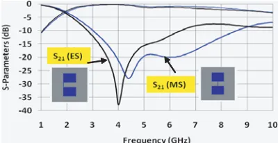
shift in the cutoff and the attenuation frequencies. The attenuation frequency is shifted from 4.4 GHz to 4.0 GHz, while the cutoff frequency shifted from 1.98 GHz to 1.855 GHz. So the movement of slot under the microstrip line to the edge give sharp transition and reduce the cutoff frequency which give a compact size. But the stopband of (ES) not have a good performance. Using the periodic effect for the dumbbell slots based on the exponential form as (e0.5, e1, e0.5) [2], if the center dumbbell slot dimension is (8 ×8 mm), the two outer slots will be (4.8 ×4.8 mm). The simulation of such design is shown in Fig. 2, for both cases of (MS) and (ES). The cutoff frequencies are 2.93 GHz and 3.28 GHz for (MS) and (ES), while the attenuation frequencies are 4.40 GHz and 4.65 GHz for (MS) and (ES) respectively. Although, the cutoff frequency for (ES) case is higher than (MS), but it achieves a better transition band. The passband for (ES) case need some modifications to be accepted. These modifications are done as follows; changes the center square slots (8 ×8 mm) to an inverted triangle and change also the outer square slots (4.8×4.8 mm) to the reshaped dumbbell slots, with a dimension that given at Fig. 3.
Figure 1. The simulated S-parameters for slot under line is in the middle (MS) or at the edge (ES) of two 8×8 mm square dumbbell slots.
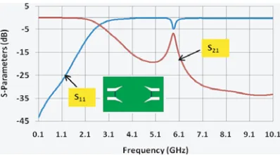
For the use of inverted triangle only, the lowpass performance gives a cutoff and attenuations frequencies equal to 2.3 GHz and 5.5 GHz, respectively, Fig. 4. The passband for such case is very good and also it gives good response in the stopband range. When the outer dumbbell slots are reshaped using dimensions as given in Fig. 3, the simulated S-parameters are shown in Fig. 5. The performance for these two reshaped rectangular dumbbell slots have harmonic at frequency (5.85 GHz) which can be compensated by the addition of the inverted triangle dumbbell slots that have higher attenuation at the same frequency, Fig. 4.
Figure 2. The simulatedS-parameters for each of (MS) or (ES) when use three periodic dumbbell slots.
4.05 4.05 9.6
5.0 2.55 4.8
30
Figure 3. The geometric dimension of the reshaped dumbbell slots, all dimension are in (mm).
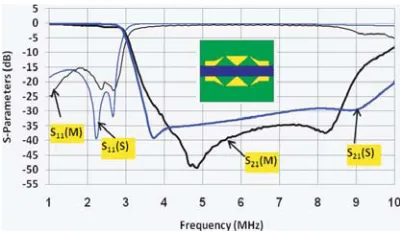
simulatedS-parameters are shown at Fig. 6. The cutoff frequency (fc) is 2.91 GHz, while the attenuation frequency (fa) is 3.72 GHz, which give sharp transition. The harmonics are suppressed up to 10 GHz with attenuations less than (−20 dB) for the stopband. The width of the microstrip line was increased from 4 mm to 5 mm to match the impedance. The attenuation in the passband is less than (−15 dB) overall the band from 1.0 GHz up to 2.75 GHz. The designed lowpass filter have a dimension of 33×30 mm2, which achieve compact size when compared with the conventional lowpass filter. In fact, The idea of (ES) was used before in [9] to widen the stopband of the lowpass filter, the stop band was extended from 2.0 GHz up to 7.2 GHz only. In our design, with using of (ES), the performance has a better stopband from 3.25 up to 9.25 GHz. The authors designed in [9] was based on the coupling of the under microstrip line slots, but here the coupling is dependent on the coupling of the dumbbell slots itself.
In general, the dumbbell slots with its connecting slot under the microstrip line can be represented by parallel LC circuit. The value of the inductance and capacitance are calculated using the following formula [13]:
C = 5fc
π(f2
o −fc2)
(1)
L= 250
C(πfo)2 (2)
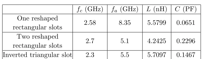
where C, L and F are measured by Pico farad (pF), nano henry (nH) and GHz, respectively. The frequencies fo and fc represent the attenuation and cutoff frequency. The equivalent circuits with its corresponding LC circuits when using one or two of the reshaped rectangular slots or using an inverted triangular slot are shown in Fig. 7. All details for these configurations are shown in Table 1.
There are two equivalent circuits can be used to represent the three dumbbell slots; the first equivalent circuit based on Fig. 7(a) and
Table 1.
fc (GHz) fa (GHz) L(nH) C (PF) One reshaped
rectangular slots 2.58 8.35 5.5799 0.0651 Two reshaped
Fig. 7(c) is shown in Fig. 8; while the second equivalent circuits based on Figs. 7(b) and Fig. 7(c) is shown in Fig. 8(b). The shunt capacitors appear due to the coupling between the center and outer dumbbell slots.
Figure 5. The simulated S-parameters for the reshaped rectangular dumbbell slots.
Figure 6. The simulated S-parameters for the the three dumbbell slots.
The simulated S-parameters for the equivalent circuits of Figs. 8(a) and (b) is given in Fig. 9. The cutoff frequency for both of the equivalent circuits (Figs. 8(a) and (b)) are the same and equal to 2.92 GHz, while the attenuation frequency is 5.1 GHz for Fig. 8(b) and it is 7.0 GHz for Fig. 8(a). The general performance of the equivalent circuits is similar to the simulated performance of Fig. 6.
3. FABRICATION AND MEASUREMENTS
(a)
5.5799 nH
0.0651 pF
(b)
4.2425 nH
0.2296 pF
(c)
5.7097 nH
0.1467 pF
Figure 7. The equivalent circuit for dumbbell slots, (a) one reshaped dumbbell slot, (b) two reshaped dumbbell slots, (c) triangle dumbbell slot.
(a)
5.5799 nH
0.0651 pF
0.85 pF 0.85 pF
Zo
Zo
Vs
5.7097 nH
0.1467 pF 5.5799 nH
0.0651 pF
(b)
0.72 pF
Zo 5.7097 nH
0.1467 pF Vs
Zo
4.2425 nH
0.2296 pF
Figure 8. The equivalent circuit for the lowpass filter with three dumbbell slots.
measured return loss (S11) of the realized defected ground lowpass
filter is less than (−15 dB) in the passband. The cutoff frequency for the simulated is 2.95 GHz, while it is 3.1 GHz for the measured lowpass filter and this shift is due to the tolerance in fabrications of the defected ground slots. The measured insertion loss (S21) is better
Figure 9. The simulated S-parameters for the equivalent circuits of Fig. 8.
Figure 10. The measured and simulatedS-parameter for the defected ground lowpass filter.
all the stopband up to 8.65 GHz and less than (−15 dB) from 8.65 up to 9.25 GHz. The overall dimension of the realized lowpass filter is 33×30 mm2, which achieve a compact size when compared with conventional lowpass filter. The measured lowpass filter with defected ground gives sharp transition with good passband and stopband. 4. CONCLUSION
have a compact size (33×30 mm2) when compared with regular lowpass filter that operating at the same frequency.
ACKNOWLEDGMENT
The author would like to acknowledge the assistance and financial support provided by the Research Center in the College of Engineering at King Saud University, Saudi Arabia.
REFERENCES
1. Ahn, D., J. S. Park, et al., “A design of the low pass filter using novel microstrip defected ground structures,” IEEE Trans. on Microwave Theory Techniques, Vol. 49, No. 1, 86–92, 2001. 2. Liu, H., et al., “An improved 1-D periodic defected ground
structure for microstrip line,” IEEE Trans. on Microwave and Wireless Components Letters, Vol. 14, No. 4, 180–182, Apr. 2004. 3. Hong, J.-S. and B. Karyamapudi, “A general circuit model for defected ground structures in planar transmission line,” IEEE Trans. on Microwave and Wireless Components Letters, Vol. 15, No. 10, 706–708, 2005.
4. Boutejdar, A., A. Ramadan, M. Makkey, and A. S. Omar, “Design of compact Microstrip lowpass filters using a U-shaped defected ground structure and compensated microstrip line,” Proceedings of the 36th European Microwave Conference, 267–270, 2006. 5. Parui, S. K. and S. Das, “A simple defected ground structures with
elliptical lowpass filtering response,” Proceeding of Asia Pacific Microwave Conference, 2007.
6. Vagner, P. and M. Kasal, “Design of novel microstrip low-pass filter usingdefected ground structures,” Microwave and Optical Technology Letter, Vol. 50, No. 1, 10–13, 2007.
7. Yang, J. and W. Wu, “Compact elliptic-function lowpass filter using defected ground structure,” IEEE Microwave and Wireless Components Letters, Vol. 18, No. 9, 578–580, Sept. 2008.
8. Boutejdar, A., M. Makkey, A. Elsherbini, O. Luxor, and A. Omar, “Design of compact extended-stopband microstrip low pass filters by employing new mutual coupling technique for defected ground structures (DGSs),” Proceeding of the 37th European Microwave Conference, 71–74, Munich Germany, Oct. 9–12, 2007.
equilat-eral U-shaped defected ground structures,”IEEE Microwave and Wirless Components, Vol. 16, No. 5, 240–242, May 2006.
10. Mohan, A. and A. Biswas, “A novel compact defected ground structure (DGS) lowpas filter,” Proceeding of Asia-Pacific Microwave Conference, 2006.
11. Boutejdar, A., J. Mochac, L. Haiwen, and A. Omar, “Miniaturized lowpass filter with wide stopband using suspended layers and defected ground structures,” 14th Conference on Microwave Technique (COMTE), 1–4, Apr. 23–24, 2008.
12. Zeland software Inc., IE3D software package, Ver.9.35, Zeland Softeare Inc., 2002.