Rephrasing Essentials of Object Oriented
Programming based on Testing Pre-requisites
Amarnath Singh, Biswajit Bishoyee, Santosh Kumar Rath, Dharmananda Parida
Dept of Computer Science & Engineering Gandhi Institute for Education & Technology
Bhubaneswar, Orissa, India
Abstract-Even after thorough testing of a program, usually a few bugs still remain. These residual bugs are usually uniformly distributed throughout the code. It is observed that bugs in some parts of a program can cause more frequent and more severe failures compared to those in other parts. It should, then be possible to prioritize the statements, methods and classes of an object-oriented program according to their potential to cause failures. Once the program elements have been prioritized, the testing effort can be apportioned so that the elements causing most frequent failure are tested more. Based on this idea, in this paper we propose a program metric called the influence of program elements. Influence of a class indicates the potential of class to cause failures. In this approach, we have used the intermediate graph representation of a program. The influence of a class is determined through a forward slicing of the graph. Our proposed program metric can be useful in applications such as coding, Debugging, test case design and Maintenance etc
Key Words: Prioritization of Program Elements, Slicing, Intermediate representation, Program testing, Object-oriented programming
1. INTRODUCTION
Software solutions are increasingly permeating our everyday life. Software industries are in immense pressure to provide very reliable products where tolerance to bugs is very less. Usually testing of the software products is carried out in various levels to identify all defects existing in the software product. However, for most practical systems, even after satisfactorily carrying out the testing process, it is not possible to guarantee that a software product is error free. This situation is caused by the fact that input data domain of most software products is very large. Also, each software product development project is constrained by time and cost. As a result, it is not practical to test a software product exhaustively using each value that the input data may assume. At present, testing takes on an average 50% of the total development cost and time. Thus, possibility of increasing the testing effort any further appears bleak. In traditional testing techniques, each element of the software product is tested with equal thoroughness. This causes usually a uniform distribution of bugs in the software product. But presence of bugs in some parts causes more severe and frequent failures than other parts. For example, if a statement produces crucial data that is useful for many other statements, then an error in this statement would affect many other statements. So our
which more exhaustive testing has to be carried out. We define influence of an element as the measure of criticality and severity of that element. We proposed a metric to compute the influence of a statement and influence of a method. With the help of these two metrics we can calculate the influence of a class. The characterization of code can help in designing, coding, testing and maintenance phases of software development cycle.
1.1Motivation for our work
In modern day society software’s are used in almost every work. The nature of this software’s can be of moderate to highly critical. Failures occurred in few software’s may not be of big concern while it can be disastrous in others like health monitoring sotwares. Each software is to be developed in given time limits and in limited resources. Time and resources used in testing phase of software development cycle is about 50%. Now a days, most of the programs are object-oriented. These object-oriented programs are quite large and complex. It is much difficult to debug and test these products. Program slicing techniques have been found to be useful in applications such as program understanding, debugging, testing, software maintenance and reverse engineering.
Metrics help in appropriate design of test cases. The important problem during test case design is that certain statement or part of the program may be more crucial than others; hence they need to be tested more thoroughly than others. Dynamic analysis of program run can’t find the problems that don’t happen in that run. Prioritizing of the statements and the functions were so far done based on the dynamic analysis. Criticality of the statements and the functions based on static analysis is not yet done. This motivates us to develop a program metric for finding the influence of elements or object-oriented program. In the next section, we identify major goals of the thesis.
1.2 Objective of our work
2. RELATED WORK:
2.1 Using Usage-Based Reading (UBR) technique
According to Schaech testing is not a separate phase in software development life cycle. Testing must be done in each phase. Special attention can be given, in each phase of software development cycle, to the high priority elements to reduce the probability of errors in these elements. From requirement analysis to design phase, only non execution based testing like inspection and review techniques are applied. Prioritization of components is also necessary at these phases to achieve better reliability level of the product within the time constraints. Some work has been done at the analysis and design level to identify the components, in which a major error can severally affect the reliability of the system. In a software project, a set of use cases are produced first. These use cases represent the principal way in which the system is to be built. These set of use cases act as a basis for system design and testing. So, it is necessary to prioritize the use cases
2.2 Slicing
A program slice is a part of the code that contributes in computation of certain variable at a program point of interest. More formally a slice can be defined as follows:
Program Slice: For statement s and variable v, the slice of a
program P with respect to the slicing criterion < s, v >
includes only those statements of P needed to capture the behavior of v at s.
Static Slicing: this technique uses static analysis to derive slicing. That is, the source code of the program is analyzed and the slices are computed for all possible input values. No assumptions are made about the input values. Since the predicates may evaluate either to true or false for different values, conservative assumptions have to be made, which may lead to relatively large slices.
Dynamic Slicing: Dynamic slicing makes use of the information about a particular execution of a program. The execution of a program is monitored and the dynamic slices are computed with respect to execution history. A dynamic slice with respect to a slicing criterion < s, v >, for a
particular execution, contains those statements that actually affect the slicing criterion in the particular execution. Therefore, dynamic slices are usually smaller than static slices and are more useful in interactive applications such as program debugging and testing.
Backward slice: Backward slicing contains those parts of the program that might directly or indirectly affect the slicing criterion. Thus a static backward slice provides the answer of the question: “which statements affect the slicing criterion?” Forward Slice: Forward slice with respect to a slicing criterion < s, v > contains all the parts of the program that
might be affected by the variables in v used or defined at the
program points. A forward slice provides the answer to the question: “which statements will be affected by the slicing criterion?
3.PROGRAM REPRESENTATION
In the following, we present a few basic concepts associated with intermediate representation of program that are used in later sections.
3.1 Control Flow Graph
The control flow graph (CFG) is an intermediate representation for programs that is useful for data flow analysis and for many optimization code transformations such common sub expression elimination, copy propagation, and loop invariant code motion.
3.2 Program Dependence Graph
The program dependence graph G of a program P is the
graph G = (N, E), where each node n 2 N represents a
statement of the program P. The graph contains two kinds of
directed edges: control dependence edges and data dependence edges. A control (or data) dependence edges (m, n) indicates that n is control (or data) dependent on m. Note
that the PDG of a program P is the union of a pair of graphs:
Data dependence graph and control flow graph of P.
3.3 System Dependence Graph
The PDG can’t handle procedure calls. Hurwitz. Introduced the System Dependence Graph (SDG) representation which models the main program together with all associated procedures. The SDG is very similar to the PDG. Indeed, a PDG of the main program is a sub graph of the SDG. In other words, for a program without procedure calls, the PDG and SDG are identical. The technique for constructing an SDG consists of first constructing a PDG for
every procedure, including the main procedure, and then adding dependence edges which link the various sub-graphs together. An SDG includes several types of nodes to model procedure calls and parameter passing:
• Call-site nodes represent the procedure call statements in the program.
• Actual-in and actual-out nodes represent the input and output parameters at call site.
They are control dependent on the call-site nodes.
• Formal-in and formal-out nodes represent the input and output parameters at called procedures. They are control dependent on procedure’s entry node. Control dependence edges and data dependence edges are used to link the individual PDGs in an SDG. The additional edges that are used to link the PDGs are as follows:
• Call edges link the call-site nodes with the procedure entry nodes.
• Parameter-in edges link the actual-in nodes with the formal-in nodes.
• Parameter-out edges link the formal-out nodes with the actual-out nodes.
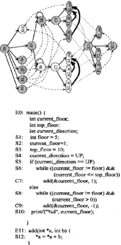
Fig. A. Example program main and its System dependence
graph.
4.PROPOSED METHODS
4.1 Prioritization of Program Elements
In this section, we present our approach to prioritize program elements in accordance to the thoroughness with which they should be tested. We first provide an overview of our approach. Subsequently we provide our approaches to calculate the influence of statement, influence of method and influence of class respectively.
4.1.1. Overview of Our Approach
An object-oriented program comprises of a set of classes. We assume that each class consists of variables and methods. Influence of a class is sum of influence of all its elements. So we calculate influence of each statement and if a statement involves a method call then influence of method will also be calculated. Our approach is based on static analysis of the code and it does not consider the value of variables. So it
can’t deal with recursive function calls and loops effectively. Sum of influence of all statements and all relevant methods is the influence of class. This approach statically computes the influence of a class. Execution of program is not necessary. First, we construct the intermediate representation (SDG/ESDG) of the program. Then, we calculate the influence of desired element using the proposed algorithms. We first discuss computation of influence of a statement, then subsequently influence of method and influence of class are discussed.
4.1.2 Influence of a Statement
In a program the result of one statement may depend on the result computed by other statements. If the influence is more, then the statement is more critical. The influence of the statement is defined by the number of other statements of the given program which use that variable directly or indirectly. We give a metric to calculate influence considering no call vertex. If a statement is call vertex then its influence will be calculated separately using the influence of
method metric and will be added to get total influence of the desired statement. Influence of the statement expressed as a percentage is given by:
Let us say Influence (u, stmt) denote the node u and statement
‘stmt0, where stmt can be any variable or ‘if’ or ‘while’ or
‘printf’ etc. Let (x1, u1), (x2, u2), ... (xk, uk) be all there
outgoing data flow edges of u in the PDG of that program.
Where x1, x2, ..., xk are dependency edges and u1, u2, ..., uk
are nodes. So influence of a statement corresponding to node
u is given by:
Influence(u, stmt) = {u1, u2, ..., uk} [{Influence(u1, stmt1)[Influence(u2, stmt2)[. . .[Influence(uk, stmtk)}
Algorithm
Input: Program code and the statement. Output: Inf luence of given statement. StmtInfluence (statement){
1. Construct ESDG of the program statically.
2. For statement traverse it’s all dependency edges and mark them.
3. For each marked node repeat step 2 until no dependency edges are found.
4. If any marked node is a call vertex then calculate its influence using
Method Influence (call vertex).
5. Count marked nodes and calculate Influence using expression (1).
6. Stop. }
4.1.3. Influence of a Method
method is defined by the number of other statements and other methods of the given program, which uses the results computed by the method directly or indirectly. If other methods are called by the given method for which we want to find the influence, then the overall influence of the method will be influence of the method itself and the influence of other called methods. We first represent the input program in ESDG as intermediate representation and after that we apply our proposed algorithm on resulting ESDG. Then we count the number of nodes influenced from that method’s formal parameter out nodes as well as other called method’s formal out parameters and we count the total no nodes in graph. The influence of a method expressed as a percentage is given by:
Algorithm
Input: A program and name of the method of that program. Output: Influence of the method.
Method Influence (call vertex){ 1. Construct ESDG of the program.
2. For the method entry vertex of the method traverse all edges and mark them visited.
3. For each visited node traverse through it’s all edges marking it’s corresponding node as
visited and if it is not a call-vertex node then mark it as influenced if not marked already.
4. Check each visited node and if it is a call vertex, traverse through it’s call edge and:
(a) If next node is polymorphic call vertex then traverse through each polymorphic edge and insert corresponding node in a queue Q.
(b) Else insert the node in Q.
5. Take out nodes from Q. Mark the node influenced and repeat step 2 to 4 for the node.
6. Repeat step 5 until Q is empty.
7. For each node marked as influenced traverse it’s all the edges and mark each as influenced if not marked already. 8. Calculate influence for the method using expression (2). 9. Stop.
}
4.1.4. Influence of a class
The influence of a class is defined as the sum of the influence of other elements of the given program which are using results of the class directly or indirectly. We first represent the input program in ESDG as intermediate representation and after that we apply our proposed algorithm on resulting ESDG. Then, we count the number of nodes influenced. Influence of nodes which involves function call will be calculated by theMethodInfluence (call vertex) metric
while, influence of all other statements are calculated using
StmtInfluence(statement) metric.
The influence of a class is given as:
Algorithm
Input: Sample program and name of the class. Output: Influence of the class.
Class Influence (class name) {
1. Construct the ESDG of the program statically.
2. Traverse to each member of the class through class entry vertex and mark each as visited.
3. For each visited node traverse through its all edges marking it’s corresponding node as
visited and if it is not a call-vertex node then mark it as influenced if not marked already.
4. Check each visited node and if it is a call vertex then
calculate influence of this statement using Method Influence (call vertex).
5. For each node marked as influenced traverse it’s all the edges and mark each as influenced
if not marked already.
6. Calculate influence of the given class using expression (3). 7. Stop.
}
4.1.5. Complexity Analysis
If N number of nodes are created in ESDG, at each node there
can be maximum N − 1 number of edges.
So, worst case space complexity will be N × (N − 1) = O(N2).
Similarly, in the PDG (SDG) any edge is visited at most once.
Time complexity= O(m) where m is a total number of edges
5.THREATS TO VALIDITY OF RESULTS
It is required for an experimental study that the results be valid for most general and real life cases. It will be invalid to perform experimental studies for some particular and biased test suites, inputs or failures which may not be targeting real faults. In order to justify the validity of the results of our experimental studies we got the following list of threats: • Biased test suite design and influencing results. • Seeding biased errors in two copies of each case study. • Testing only for selected failures and loosing generality of results.
• Using testing methodologies which may only be suitable for some particular bugs while may not reveal other common and frequent bugs.
5.1 Measures taken to overcome the threats
In order to overcome the above mentioned threats and validate the results for most common and real life cases, we have taken the following corrective measures:
• Designed same test suite for both traditional and prioritized testing.
• Used same seeded faults for both the copies.
• We have taken care that the seeded faults match with commonly occurring bugs.
• We have taken in consideration following four kind of failures which include almost all variety of bugs.
2. Major: Defects that would cause serious consequences for the system like loosing
some important data.
3. Minor: Defects that can cause small or negligible consequences for the system. Ex.
displaying results in some different format.
5.2. Results
4. No Effect: This may not necessarily hamper the system performance, but they may give slightly different interpretation and generally avoidable. Ex. simple typographic errors in documentation.
• We have inserted mutation operator to seed fault. Using mutation operator we can not guarntee that the faults seeded are representatives of a particuler population, but we can ensure that a wide variety of fults are systemmatically inserted in a somewhat impartial and random fashion
CONCLUSION
We have purposed a program metric which called the influence of program elements. The influence shows that which elements affect more than others in a program. So the elements with higher influence are more critical and presence of bugs in them will increase the probability of failure of software. So, the purposed metrics greatly help in finding out the more critical elements and guides to take utmost care in developing the elements with higher influence during software development cycle. This also suggests that elements with least priority can be tested with least number of test cases rather than giving similar efforts as more critical elements and hence saving the very important time for testing the more critical elements.
• It is based on static analysis of a program.
• Useful in test case design and test case prioritization. • Useful to characterize the influence of various components of the program. So one can have more reliable components to be tested thoroughly.
REFERENCES
[1] Horwitz S., Reps T., and Binkley D. Inter-procedural slicing using dependence graphs.ACM Transactions on Programing Languagees and Systems 12, 1(1990), 26-61.
[2] Zhang X., Gupta R., and Zhang Y. Efficient forward computation of dynamic slices using reduced ordered binary decision diagrams. In International conference of Software Engineering(2004).
[3] Agrawal H., DeMillo R, A., and Spafford E. H. Debugging with dynamic slicing and backtracking. Software Practice and Experience 23, 6(1993), 589-616.
[4] Dhamdhare D.M., Gururaja K., and Ganu P. G. A compact education history for dynamic slicing. Information Processing Letters 85(2003), 145-152.
[5] Korel B., and Rilling J. Dynamic Program Slicing Methods. Information and Software Technology 40(1998), 155-163.
[6] Xu B., Qian J., Zhang X., Wu Z., and Chen L. A Brief Survey of program slicing. ACM SIGSOFT Software Engineering Notes 30, 2(2005), 1-36.
[7] WeiserM. Programmers use slices when debugging. Communication of ACM25, 7(1982),446-452.
[8] Ball T. The Use of Control Flow and Control Dependence in Software Tools. PhD thesis,Computer Science Department, University of Wisconsin-Madison, 1993.
[9] Song Y., and Huynh D. Forward Dynamic Object-Oriented Slicing. Application Specific Systems and Software Engineering and Technology(ASSET’99). IEEE CS Press, 1999.