ISSN (Print) : 2320 – 3765 ISSN (Online): 2278 – 8875
I
nternational
J
ournal of
A
dvanced
R
esearch in
E
lectrical,
E
lectronics and
I
nstrumentation
E
ngineering
(An ISO 3297: 2007 Certified Organization)
Vol. 4, Issue 1, January 2015
A Single Phase Grid Connected Converter for
Renewable Energy Distributed Systems
S. Srinivas1, N. Kiran Kumar2, M. Satyanarayana3
Student, Department of EEE, Vaageswari College of Engineering, Karimnagar, Telangana, India1
Asst. professor, Department of EEE, Vaageswari College of Engineering, Karimnagar, Telangana, India 2
Research Assistant, Department of Electrical Engineering, Hyderabad, Telangana, India3
ABSTRACT:In low power renewable systems, a single phase grid-connected converter is usually adopted. This paper deals with a novel five-level converter topology that follows this trend. A review of the state of the art of the five-level topologies and a theoretical power loss comparison with the proposed solution is realized. The proposed converter architecture is based on a full-bridge topology with two additional power switches and two diodes connected to the midpoint of the dc link. Since the two added levels are obtained by the discharge of the two capacitors of the dc link, the balancing of the midpoint voltage is obtained with a specific pulse width modulation (PWM) strategy. Simulation results carried on MATLAB/SIMULINK model design show the effectiveness of the proposed solution.
KEYWORDS: Distributed power Generation, DC- AC power conversion, grid- connected converters, Single - phase systems, multilevel converters.
I. INTRODUCTION
With regard to harmonic distortion content, power factors, and dc components, the output current of grid connected power converters must comply with the requirements of electricity supply companies. Multilevel converters have been under research and development for more than three decades and have found successful industrial application. However, this is still a technology under development, and many new contributions and new commercial topologies have been reported in the last few years. The aim of this paper is to group and review these recent contributions, in order to establish the current state of the art and trends of the technology, to provide readers with a comprehensive and insightful review of where multilevel converter technology stands and is heading [1]. This paper first presents a brief overview of well-established multilevel converters strongly oriented to their current state in industrial applications to then center the discussion on the new converters that have made their way into the industry [2]. Recently, converter topologies employing a high-frequency transformer instead of a line frequency one have been investigated in order to reduce size and weight. The tradeoff between high efficiency and low cost is a hard task for these architectures because they require several power stages. On the other hand, in low-power applications, international standards allow the use of grid-connected power converters without any galvanic isolation, thus allowing the so called transformerless architectures. This paper concerns the use of multilevel topologies for single-phase converters, but in order to remain linked to a practical implementation, the unipolar PWM applied to a full bridge topology is taken as reference. It is important to note that, in this paper, the term unipolar PWM refers to a three-level output voltage, whose first switching harmonic resides at twice the switching frequency [3]. The unipolar PWM is always applied to a full-bridge structure.
II. CIRCUIT TOPOLOGY
ISSN (Print) : 2320 – 3765 ISSN (Online): 2278 – 8875
I
nternational
J
ournal of
A
dvanced
R
esearch in
E
lectrical,
E
lectronics and
I
nstrumentation
E
ngineering
(An ISO 3297: 2007 Certified Organization)
Vol. 4, Issue 1, January 2015
A. PROPOSED FIVE LEVEL SINGLE PHASE SOLUTION
The proposed converter is shown in Fig. 2.1. This converter architecture, known as the H6 Bridge, was originally developed in combination with a suitable PWM strategy, in order to keep constant the output common-mode voltage in
case of a transformerless inverter for photovoltaic applications.
Fig 2.1 proposed five level full bridge topology.
In this paper, this converter structure is used to obtain a five-level grid-connected converter for single-phase
applications. In steady-state conditions, due to the low voltage drop across the inductance Lf of the output filter, the
output voltage of the converter has a fundamental component very close to the grid voltage. The frequencies of these two voltages are identical, whereas the amplitude and their phase displacement are only slightly different. As a
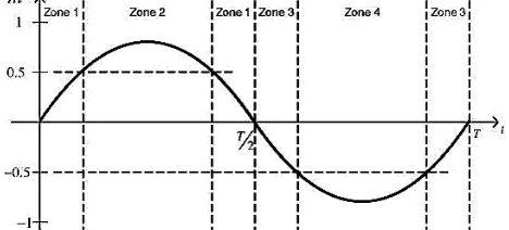
consequence, the shape of the modulation index m of the power converter is very similar to the grid voltage
waveform.[5,6,7]
The output voltage of the converter can be written as Vout = mVdc. Depending on the modulation index value, the power converter will be driven by different PWM strategies. As a matter of fact, it is possible to identify four operating zones as shown in fig 2.2.
Fig 2.2 Modulation index waveform explaining the four different PWM zones as stated
For each zone, the output voltage levels of the powerconverter will be different, as shown in Table I.
Table. I
Expected output Voltages in Different Zones
III. ZONES OF OPERATION OF PROPOSED CONVERTER MODEL
ISSN (Print) : 2320 – 3765 ISSN (Online): 2278 – 8875
I
nternational
J
ournal of
A
dvanced
R
esearch in
E
lectrical,
E
lectronics and
I
nstrumentation
E
ngineering
(An ISO 3297: 2007 Certified Organization)
Vol. 4, Issue 1, January 2015
ON. During the negative semi period the full bridge changes configuration, with T1 and T4 OFF and T2 and T3 ON. With similarity to Zone 1 and 2, in Zone 3 T5 commutates while T6 is OFF, and in Zone 4 T5 in ON and T6 commutates.
Fig 3.1 gate signal generation using proposed PWM technique for complete cycle of AC output...
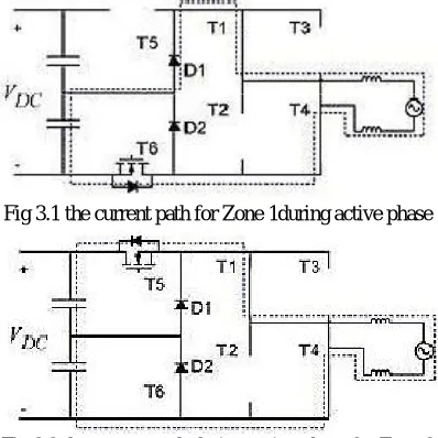
The gate signals for finishing a cycle is clearly presented in fig 3.1. The direction of current path during the positive half period in Zone 1 and Zone 2 are shown in the figures 3.2 and 3.3 respectively. The controlled power switches that are ON during the whole PWM period are substituted by a solid line, whereas devices that are OFF during the whole PWM periods are not displayed in fig. 3.1respectively.
Fig 3.1 the current path for Zone 1during active phase
Fig 3.2 the current path during active phase for Zone 2
In Zone 1 the switching of the transistor T6 changes the output value between +VMP is provided by the low side
capacitor as seen in Fig 3.1 and 0 V during the freewheeling phase both diodes D1 and D2 are ON, imposing an almost null voltage at the full-bridge output asshown in fig 3.3 for each dead time period of about 3 to 5µs.
In Zone 2 T6 is ON and the switching of T5 changes the output voltage from +Vdc to +VMP as seen in fig 3.2. A
ISSN (Print) : 2320 – 3765 ISSN (Online): 2278 – 8875
I
nternational
J
ournal of
A
dvanced
R
esearch in
E
lectrical,
E
lectronics and
I
nstrumentation
E
ngineering
(An ISO 3297: 2007 Certified Organization)
Vol. 4, Issue 1, January 2015
Fig 3.3 freewheeling phase during dead time.
It must be observed that only a transistor is switching for every zone. Furthermore, the anti-parallel diode of every power switch is not used allowing the use of MOSFETs for all the transistors
IV. SIMULATION MODEL DESIGN OF PROPOSED CIRCUIT
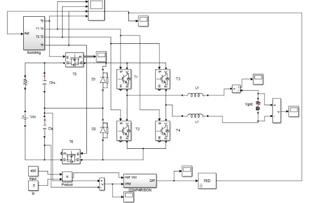
Grid-tie inverters are also designed to quickly disconnect from the grid if the utility grid goes down. This is an NEC requirement that ensures that in the event of a blackout, the grid tie inverter will shut down to prevent the energy it transfers from harming any line workers who are sent to fix the power grid. Properly configured, a grid tie inverter enables a home owner to use an alternative power generation system like solar or wind power without extensive rewiring and without batteries. If the alternative power being produced is insufficient, the deficit will be sourced from the electricity grid.The simulation design of proposed converter connected to grid is shown below in fig 4.1. The closed loop system with proposed unipolar PWM gate signal generation is provided.
Fig 4.1 proposed system in Matlab Simulink model design
The main advantage of the proposed system is with the balancing of the split capacitor voltage according to the requirement of the active power need is like demand verses supply with available power quantity check.
ISSN (Print) : 2320 – 3765 ISSN (Online): 2278 – 8875
I
nternational
J
ournal of
A
dvanced
R
esearch in
E
lectrical,
E
lectronics and
I
nstrumentation
E
ngineering
(An ISO 3297: 2007 Certified Organization)
Vol. 4, Issue 1, January 2015
Fig 4.2 gate pulses for the proposed converter
The output voltage of the proposed five-level converter based on a full-bridge converter with two added power switches
and two diodes connected to the midpoint of the dc link obtained in the Simulink model is ±400 peak-peak and
the output waveforms are shown in Fig. 4.3.
Fig 4.3 peak-peak outputvoltage waveform
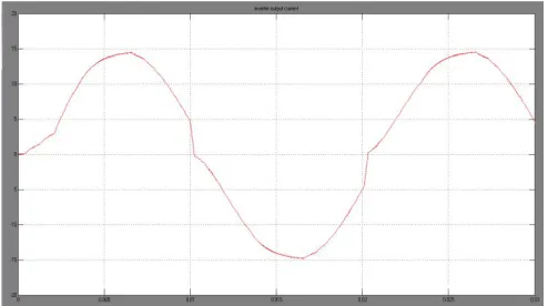
The figure 4.4 describe the converter grid injected current with the amplitude of the 10 A. The shape of the waveform is almost harmonic free sinusoidal
ISSN (Print) : 2320 – 3765 ISSN (Online): 2278 – 8875
I
nternational
J
ournal of
A
dvanced
R
esearch in
E
lectrical,
E
lectronics and
I
nstrumentation
E
ngineering
(An ISO 3297: 2007 Certified Organization)
Vol. 4, Issue 1, January 2015
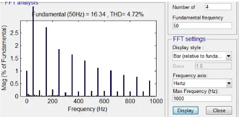
The THD analysis is also compared for the simulation which is shown in Fig. 4.5. The total harmonic distortion in grid
currents is 4.72% for the selected signals of five obtained using the FFT analysis
Fig 4.5 THD of the output voltage waveform
V. APPLICATIONS
1. Power conditioning.
2. Motor drives.
3. UPS.
VI. ADVANTAGES
1. Reduced harmonic.
2. Less EMI.
3. Smaller & Cheaper filter.
4. Reduced switching power losses.
5. Power factor improvement
VII. CONCLUSION
This paper is proposed with a five level full bridge MC for single-phase grid connected converters. The converter topology uses the midpoint voltage of the dc link to provide two more output voltage levels, decreasing switching power losses and EMI. In order to obtain the minimum number of commutations to maximize efficiency, the PWM strategy was used. Simulations results showed are depicting that the feasibility of the proposed converter architecture and the ability of the MVC to compensate for system asymmetries. Experimental results showed that the effectiveness of the proposed solution in terms of THD is good about 4.7% only.
VIII. FUTURE SCOPE
The system can be developed to high level that can further reduce the distortion. As the structure of this project itself implies that it can be very simple and very efficient one. Solar power plant is emerging trend to extract the electrical power. In future this design may more help to invert the power and directly fed to the grid.
REFERENCES
1. F.-P. Zeng, G.-H. Tan, J.-Z. Wang, and Y.-C. Ji, “Novel single-phase five level voltage-source inverter for the shunt active power filter,” Power Electron., vol. 3, no. 4, pp. 480–489, Jul. 2010.
2. R. Gonzalez, E. Gubia, J. Lopez, and L. Marroyo, “Transformerless single-phase multilevel-based photovoltaic inverter,” IEEE Trans. Ind. Electron., vol. 55, no. 7, pp. 2694–2702, Jul. 2008.
3. D. Barater, G. Buticchi, A. S. Crinto, G. Franceschini, and E. Lorenzani, “A new proposal for ground leakage current reduction in transformerless grid-connected converters for photovoltaic plants,” in Proc. 35th IEEEIECON, Nov. 2009, pp. 4531–4536.
ISSN (Print) : 2320 – 3765 ISSN (Online): 2278 – 8875
I
nternational
J
ournal of
A
dvanced
R
esearch in
E
lectrical,
E
lectronics and
I
nstrumentation
E
ngineering
(An ISO 3297: 2007 Certified Organization)
Vol. 4, Issue 1, January 2015
5. Q. Mei, M. Shan, L. Liu, and J. Guerrero, “A novel improved variable step-size incremental-resistance MPPT method for PV systems,” IEEE
Trans. Ind. Electron., vol. 58, no. 6, pp. 2427–2434, Jun. 2011.
6. R. Kadri, J.-P. Gaubert, and G. Champenois, “An improved maximum
7. Power point tracking for photovoltaic grid-connected inverter based on voltage-oriented control,” IEEE Trans. Ind. Electron., vol. 58, no. 1, pp. 66–75, Jan. 2011.
8. IEEE Recommended Practices and Requirements for Harmonic Controlin Electrical Power Systems, IEEE Std 519-1992, 1993
9. D. Infield, P. Onions, A. Simmons, and G. Smith, “Power quality from multiple grid-connected single-phase inverters,” IEEE Trans. Power Del., vol. 19, no. 4, pp. 1983–1989, Oct. 2004.
10. R. Gonzalez, E. Gubia, J. Lopez, and L. Marroyo, “Transformerless single-phase multilevel-based photovoltaic inverter,” IEEE Trans. Ind.Electron., vol. 55, no. 7, pp. 2694–2702, Jul. 2008.
11. S. Kouro, M. Malinowski, K. Gopakumar, J. Pou, L. Franquelo, B. Wu, J. Rodriguez, M. Pandrez, and J. Leon, “Recent advances and industrial applications of multilevel converters,” IEEE Trans. Ind. Electron., vol. 57,no. 8, pp. 2553–2580, Aug. 2010.
12. J.-S. Lai and F. Z. Peng, “Multilevel converters—A new breed of power converters,” IEEE Trans. Ind. Appl., vol. 32, no. 3, pp. 509–517, May 1996.
BIOGRAPHY
S. Srinivas student member of IEEE, Graduated in B.Tech EEE in the year 2011 from Mahaveer Institute of Science and Technology, Bandlaguda, Hyderabad. Currently pursuing M.Tech in Power Electronics from Vaageswari College of Engineering, Nustullapur, Karimnagar District, Telangana, INDIA. Research interest in Semiconductor Drives, Renewable Energy Systems.
N. Kiran Kumar member of ISTE, B.Tech, M.Tech, working as ASSISTANT PROFESSOR in Dept. Of EEE from Vaageswari College of Engineering, Nustullapur, Karimnagar, Telangana, INDIA. He worked in various Engineering Colleges and have 7 years of teaching experience. He has presented 2 International Conference Papers. He has published 1 research paper in International Journals. His area of Research interest includes Switchgear Protection, Semiconductor Drives, and Electrical Distribution Systems.