c e-ISSN: 2348-6848, p- ISSN: 2348-795X Volume 2, Issue 12, December 2015
International Journal of Research (IJR)
Available at http://internationaljournalofresearch.org
Available online:http://internationaljournalofresearch.org/ P a g e | 227
Source Current Harmonics Reduction with Intelligent
controlled Multiple RES based SAPF
G. Lakshminarayana Reddy
M-tech Student Scholar Department of Electrical & Electronics Engineering, QIS College of Engineering & Technology Prakasam (Dt); Andhra Pradesh, India.
Email: [email protected]
R. Sathish Kumar
Associate Professor Department of Electrical & Electronics Engineering, QIS College of Engineering & Technology Prakasam (Dt); Andhra Pradesh, India.
Email: [email protected].
B. Venkata Prasanth
HOD of Department of Electrical & Electronics Engineering, QIS College of Engineering & Technology Prakasam (Dt); Andhra Pradesh, India.
Email:[email protected]. Abstract:
Now a day’s due to increase in the power demand, generation has to be increased. Due to which the fossil fuels are using out which creates the pollution too. Hence we are using the Renewable energy sources which neither creates pollution problems nor energy conservation problems. Renewable energy resources (RES) are being increasingly connected in distribution systems utilizing power electronic converters. In recent years, the number and variety of applications of
Hybrid Fuzzy Logic (HFL) have increased
significantly. Among the Renewable energy resources most abundantly available throughout the earth is Sun radiation. This paper presents a novel control strategy for achieving maximum benefits from these grid-interfacing inverters when installed in 3-phase 4-wire distribution systems. The inverter is controlled to perform as a multi-function device by incorporating active power filter functionality. The inverter can thus be utilized as: 1) power converter to inject power generated from RES to the grid, and 2) shunt APF to
compensate current unbalance, load current
harmonics, load reactive power demand and load neutral current. All of these functions may be accomplished either individually or simultaneously. This new intelligent (HFLC) controller based concept is demonstrated with extensive MATLAB/Simulink simulation studies.
Keywords: Hybrid FLC; Active power filter; current control; four-leg converters; predictive control.
I. INTRODUCTION
Electric utilities and end users of electric power are becoming increasingly concerned about meeting the growing energy demand. Seventy five percent of total global energy demand is supplied by the burning of fossil fuels. But increasing air pollution, global warming concerns, diminishing fossil fuels and their increasing cost have made it necessary to look towards renewable sources as a future energy solution. Since the past decade, there has been an enormous interest in many countries on renewable energy for power generation. The market liberalization and government’s incentives have further accelerated the renewable energy sector growth.
c e-ISSN: 2348-6848, p- ISSN: 2348-795X Volume 2, Issue 12, December 2015
International Journal of Research (IJR)
Available at http://internationaljournalofresearch.org
Available online:http://internationaljournalofresearch.org/ P a g e | 228 harmonic currents, which may deteriorate the quality
of power [1], [2]. Generally, current controlled voltage source inverters are used to interface the intermittent RES in distributed system. Recently, a few control strategies for grid connected inverters incorporating PQ solution have been proposed. In [3] an inverter operates as active inductor at a certain frequency to absorb the harmonic current. But the exact calculation of network inductance in real-time is difficult and may deteriorate the control performance. A similar approach in which a shunt active filter acts as active conductance to damp out the harmonics in distribution network is proposed in [4]. In [5], a control strategy for renewable interfacing inverter based on – theory is proposed. In this strategy both load and inverter current sensing is required to compensate the load current harmonics.
The non-linear load current harmonics may result in voltage harmonics and can create a serious PQ problem in the power system network. Active power filters (APF) are extensively used to compensate the load current harmonics and load unbalance at distribution level. This results in an additional hardware cost. However, in this paper authors have incorporated the features of APF in the, conventional inverter interfacing renewable with the grid, without any additional hardware cost. Here, the main idea is the maximum utilization of inverter rating which is most of the time underutilized due to intermittent nature of RES. It is shown in this paper that the grid-interfacing inverter can effectively be utilized to perform following important functions: 1) transfer of active power harvested from the renewable resources (wind, solar, etc.); 2) load reactive power demand support; 3) current harmonics compensation at PCC; and 4) current unbalance and neutral current compensation in case of 3-phase 4-wire system.
This paper presents the mathematical model of the 4L-VSI and the principles of operation of the proposed predictive control scheme, including the design procedure. The complete description of the selected current reference generator implemented in the active power filter is also presented. Finally, the proposed active power filter and the effectiveness of the associated control scheme compensation are demonstrated through simulation and validated with experimental results obtained in a 2 kVA system.
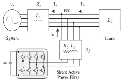
Figure 1: Stand-Alone Hybrid Power Generation System with a Shunt Active Power Filter.
Figure 2: Three-Phase Equivalent Circuit of the Proposed Shunt Active Power Filter.
II. FOUR-LEG CONVERTER MODEL
c e-ISSN: 2348-6848, p- ISSN: 2348-795X Volume 2, Issue 12, December 2015
International Journal of Research (IJR)
Available at http://internationaljournalofresearch.org
Available online:http://internationaljournalofresearch.org/ P a g e | 229
The four-leg PWM converter topology is shown in Figure 3. This converter topology is similar to the conventional three-phase converter with the fourth leg connected to the neutral bus of the system. The fourth leg increases switching states from 8 (23) to 16 (24), improving control flexibility and output voltage quality, and is suitable for current unbalanced compensation.
Figure 3: Two-level four-leg PWM-VSI topology.
The voltage in any leg x of the converter, measured from the neutral point (n), can be expressed in terms of switching states, as follows:
The mathematical model of the filter derived from the equivalent circuit shown in Figure 2 is
Where Req and Leq are the 4L-VSI output parameters expressed as Thevenin impedances at the converter output terminals Zeq. Therefore, the Thevenin equivalent impedance is determined by a series connection of the ripple filter impedance Zf and a parallel arrangement between the system equivalent impedance Zs and the load impedance ZL
For this model, it is assumed that that the resistive part of the system’s equivalent impedance is neglected, and that the series reactance is in the range of 3– 7% p.u., which is an acceptable approximation of the real system. Finally, in (2)
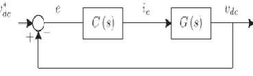
III. DIGITAL PREDICTIVE CURRENT CONTROL
The block diagram of the proposed digital predictive current control scheme is shown in Figure 4. This control scheme is basically an optimization algorithm and, therefore, it has to be implemented in a microprocessor. Consequently, the analysis has to be developed using discrete mathematics in order to consider additional restrictions such as time delays and approximations
Figure 4: Proposed Predictive Digital Current Control Block Diagram.
The main characteristic of predictive control is the use of the system model to predict the future behavior of the variables to be controlled. The controller uses this information to select the optimum switching state that will be applied to the power converter, according to predefined optimization criteria. The predictive control algorithm is easy to implement and to understand, and it can be implemented with three main blocks, as shown in Figure 4.
IV. CURRENT REFERENCE GENERATION
A dq-based current reference generator scheme is used to obtain the active power filter current reference signals. This scheme presents a fast and accurate signal tracking capability. This characteristic avoids voltage fluctuations that deteriorate the current reference signal affecting compensation performance. The current reference signals are obtained from the corresponding load currents as shown in Figure 5. This module calculates the reference signal currents required by the converter to compensate reactive power, current harmonic and current imbalance. The displacement power factor (sinφ(L)) and the maximum total harmonic distortion of the load (THD(L)) defines the relationships between the apparent power required by the active power filter, with respect to the load, as shown
c e-ISSN: 2348-6848, p- ISSN: 2348-795X Volume 2, Issue 12, December 2015
International Journal of Research (IJR)
Available at http://internationaljournalofresearch.org
Available online:http://internationaljournalofresearch.org/ P a g e | 230
generates a pure sinusoidal waveform even when the system voltage is severely distorted.
Figure 5: Dq-Based Current Reference Generator Block Diagram.
Tracking errors are eliminated, since SRF-PLLs are designed to avoid phase voltage unbalancing, harmonics (i.e., less than 5% and 3% in fifth and seventh, respectively), and offset caused by the nonlinear load conditions and measurement errors. Equation (8) shows the relationship between the real currents iLx(t) (x=u,v,w) and the associated dq components (id and iq)
The current that flows through the neutral of the load is compensated by injecting the same instantaneous value obtained from the phase-currents, phase-shifted by 180◦, as shown next
One of the major advantages of the dq-based current reference generator scheme is that it allows the implementation of a linear controller in the dc-voltage control loop. However, one important disadvantage of the dq-based current reference frame algorithm used to generate the current reference is that a second order harmonic component is generated in id and iq under unbalanced operating conditions. The amplitude of this harmonic depends on the percent of unbalanced load current (expressed as the relationship between the negative sequence current iL,2 and the positive sequence current iL,1). The second-order harmonic cannot be removed from id and iq, and therefore generates a third harmonic in the reference current when it is converted back to abc frame. Figure 6 shows the percent of system current imbalance and the percent of third harmonic system current, in function of the percent of load current imbalance. Since the load current does not have a third harmonic, the one generated by the active power filter flows to the power system.
Figure 6: DC-voltage control block diagram.
The dc-voltage converter is controlled with a traditional PI controller. This is an important issue in the evaluation, since the cost function (6) is designed using only current references, in order to avoid the use of weighting factors. Generally, these weighting factors are obtained experimentally, and they are not well defined when different operating conditions are required. Additionally, the slow dynamic response of the voltage across the electrolytic capacitor does not affect the current transient response. For this reason, the PI controller represents a simple and effective alternative for the voltage control. The dc-voltage remains constant (with a minimum value of √ 6vs (rms)) until the active power absorbed by the converter decreases to a level where it is unable to compensate for its losses.
V. INTRODUCTION TO INTELLIGENT CONTROLLER
A new language was developed to describe the intelligent properties of reality, which are very difficult and sometime even impossible to be described using conventional methods. PI with Fuzzy set theory has been widely used in the control area with some application to dc-to-dc converter system. Furthermore, design of fuzzy logic controller can provide desirable both small signal and large signal dynamic performance at same time, which is not possible with linear control technique. Thus, fuzzy logic controller has been potential ability to improve the robustness of dc-to-dc converters. The basic scheme of a fuzzy logic controller is shown in Figure 5 and consists of four principal components such as: a fuzzy fication interface, which converts input data into suitable linguistic values; a knowledge base, which consists of a data base with the necessary linguistic definitions and the control rule set; a decision-making logic which, simulating a human decision process, infer the fuzzy control action from the knowledge of the control rules and linguistic variable definitions; a de-fuzzification interface which yields non fuzzy control action from an inferred fuzzy control action [10].
c e-ISSN: 2348-6848, p- ISSN: 2348-795X Volume 2, Issue 12, December 2015
International Journal of Research (IJR)
Available at http://internationaljournalofresearch.org
Available online:http://internationaljournalofresearch.org/ P a g e | 231
The fuzzy control systems are based on expert knowledge that converts the human linguistic concepts into an automatic control strategy without any complicated mathematical model [10]. Simulation is performed in buck converter to verify the proposed fuzzy logic controllers.
Figure 8: Block Diagram of the Fuzzy Logic Controller (FLC) For DC-DC Converters.
A. Fuzzy Logic Membership Functions
The dc-dc converter is a nonlinear function of the duty cycle because of the small signal model and its control method was applied to the control of boost converters. Fuzzy controllers do not require an exact mathematical model. Instead, they are designed based on general knowledge of the plant. Fuzzy controllers are designed to adapt to varying operating points. Fuzzy Logic Controller is designed to control the output of boost dc-dc converter using Mamdani style fuzzy inference system. Two input variables, error (e) and change of error (de) are used in this fuzzy logic system. The single output variable (u) is duty cycle of PWM output.
Figure 9: The Membership Function plots of error.
Figure 10: The Membership Function plots of change error.
Figure 11: The Membership Function Plots of Duty Ratio.
B. Fuzzy Logic Rules
The objective of this dissertation is to control the output voltage of the boost converter. The error and change of error of the output voltage will be the inputs of fuzzy logic controller. These 2 inputs are divided into five groups; NB: Negative Big, NS: Negative Small, ZO: Zero Area, PS: Positive small and PB: Positive Big and its parameter [10]. These fuzzy control rules for error and change of error can be referred in the table that is shown in Table II as per below:
Table II
Table rules for error and change of error
VI. SIMULATION RESULTS
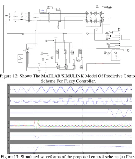
Case 1: Predictive control Scheme for 4-Leg APF
Figure 12: Shows The MATLAB/SIMULINK Model Of Predictive Control Scheme For Fuzzy Controller.
Figure 13: Simulated waveforms of the proposed control scheme (a) Phase to neutral source voltage (b) Load Current (c) Load neutral current. (d) Three phase source current. (e) Compensating currents. (f) DC voltage
c e-ISSN: 2348-6848, p- ISSN: 2348-795X Volume 2, Issue 12, December 2015
International Journal of Research (IJR)
Available at http://internationaljournalofresearch.org
Available online:http://internationaljournalofresearch.org/ P a g e | 232 Figure 14: Simulated waveforms of single phase source load compensating
currents.
Figure 15: Simulated waveforms of 3-phase source load current neutral line current compensating current source voltage.
Figure 16: Shows the Power factor.
Figure 17: Shows The Total Harmonic Distortion 29.98%. Case 2: Intelligent controller based APF
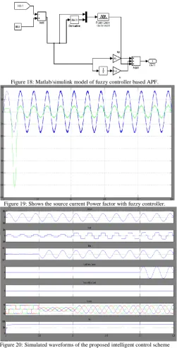
Figure 18: Matlab/simulink model of fuzzy controller based APF.
Figure 19: Shows the source current Power factor with fuzzy controller.
Figure 20: Simulated waveforms of the proposed intelligent control scheme (a) Phase to neutral source voltage (b) Load Current. (c) Compensating currents (d) Load neutral current. (e) Source neutral current (f) Three phase
c e-ISSN: 2348-6848, p- ISSN: 2348-795X Volume 2, Issue 12, December 2015
International Journal of Research (IJR)
Available at http://internationaljournalofresearch.org
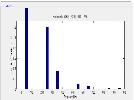
Available online:http://internationaljournalofresearch.org/ P a g e | 233 Figure 21: Shows The Total Harmonic Distortion Of Fuzzy Based APF Is
1.27%. VII. CONCLUSION
In this concept fuzzy controlled active power filter for renewable energy source is improved dynamic current harmonics and a reactive power compensation scheme for power distribution systems with generation from renewable sources has been proposed to improve the current quality of the distribution system. PI is replaced with the fuzzy controller to perform the speed operation of the converter. Advantages of the proposed scheme are related to its simplicity, modeling, and implementation. The use of a predictive control for the converter current loop proved to be an effective solution for active power filter applications. Finally this concept proposed the intelligent controller is better controller compare to the PI controller is obtained by the simulation results.
REFERENCES
[1] P. Cortes, G. Ortiz, J. Yuz, J. Rodriguez, S. Vazquez, and L. Franquelo,“Model predictive control of an inverter with outputLCfilter for UPS applications,”IEEE Trans. Ind. Electron., vol. 56, no. 6, pp. 1875–1883, Jun. 2009.
[2] R. Vargas, P. Cortes, U. Ammann, J. Rodriguez, and J. Pontt, “Predictive control of a three-phase neutral-point-clamped inverter, ”IEEE Trans. Ind.Electron., vol. 54, no. 5, pp. 2697–2705, Oct. 2007.
[3] P. Cortes, A. Wilson, S. Kouro, J. Rodriguez, and H. Abu-Rub, “Model predictive control of multilevel cascaded H-bridge inverters, ”IEEE Trans. Ind. Electron., vol. 57, no. 8, pp. 2691– 2699, Aug. 2010.
[4] P. Lezana, R. Aguilera, and D. Quevedo, “Model predictive control of an asymmetric flying capacitor converter, ”IEEE Trans. Ind. Electron., vol. 56, no. 6, pp. 1839–1846, Jun. 2009.
[5] P. Correa, J. Rodriguez, I. Lizama, and D. Andler, “A predictive control scheme for current-source rectifiers, ”IEEE Trans. Ind. Electron., vol. 56, no. 5, pp. 1813–1815, May 2009.
[6] M. Rivera, J. Rodriguez, B. Wu, J. Espinoza, and C. Rojas, “Current control for an indirect matrix converter with filter resonance mitigation,”
IEEE Trans. Ind. Electron., vol. 59, no. 1, pp. 71 79, Jan. 2012.
[7] P. Correa, M. Pacas, and J. Rodriguez, “Predictive torque control for inverter-fed induction machines, ” IEEE Trans. Ind. Electron., vol. 54, no. 2, pp. 1073–1079, Apr. 2007.
[8] M. Odavic, V. Biagini, P. Zanchetta, M. Sumner, and M. Degano, “Onesample-period ahead predictive current control for high performance active shunt power filters, ”Power Electronics, IET, vol. 4, no. 4, pp. 414–423, Apr. 2011.
[9] D. Quevedo, R. Aguilera, M. Perez, P. Cortes, and R. Lizana, “Model predictive control of an AFE rectifier with dynamic references, ”IEEE Trans. Power Electron., vol. 27, no. 7, pp. 3128– 3136, Jul. 2012.
[10] Z. Shen, X. Chang, W. Wang, X. Tan, N. Yan, and H. Min, “Predictive digital current control of single-inductor multiple-output converters in CCM with low cross regulation, ”IEEE Trans. Power Electron., vol. 27, no. 4, pp. 1917–1925, Apr. 2012.
G. Lakshmi Narayana Reddy is pursuing M-Tech at QIS college of Engineering & Technology under JNTU, Kakinada. He received his B-Tech degree from DJR Institute of
engineering & technology. JNTU
Kakinada His current research interests are Research areas Power electronics & Power systems
Sri. R. Sathish Kumar received
B.Tech. in Electrical and Electronics Engineering from Jawaharlal Nehru Technological University, Hyderabad, India, in 2005 and M.Tech in Electrical & Electronics Engineering from Jawaharlal Nehru Technological University, Hyderabad, India, in 2010. Currently, he is working as an Associate Professor in QIS College of Engineering and Technology, Ongole, India. He has published a number of papers in various national & international journals & conferences. His research areas are power system operation & control and economic load dispatch.