International Journal of Research (IJR)
e-ISSN: 2348-6848, p- ISSN: 2348-795X Volume 2, Issue 12, December 2015Available at http://internationaljournalofresearch.org
A Fuzzy Based Three-Phase Inverter for a Unified Controller
in Distributed Generation
Vuyyuru Swathi PG Scholar & Mr.K.PeddaKapu
Nova College of Engineering and Technology Jangareddy Gudem Department of Electrical and Electronics Engineering , JNTUK Andhra Pradesh, India.
Abstract:
This paper presents a novel fuzzy based three-phase inverter for a unified controller in distributed generation (DG) which enables both islanded and grid-tied modes, no need for switching between two corresponding controllers or critical islanding detection. This paper describes inner inductor current loop, and a voltage loop in the synchronous reference frame. It addresses a current source by regulating the inner current loop in grid-tied operation, and the voltage controller is automatically activated to regulate the load voltage upon the occurrence of islanding. With the conventional strategy, the current in grid-tied mode the load voltage in the islanding mode are distorted under nonlinear local load. The same is addressed by proposing a load current feed forward in this paper. The effectiveness of the techniques proposed in this paper is demonstrated by MATLAB Simulation and results are presented here.
Index Terms- Fuzzy Logic; Distributed generation (DG); islanding; load current; seamless transfer; three-phase inverter; unified control
1. INTRODUCTION
Distributed generation (DG) is emerging as a viable alternative when renewable or nonconventional energy resources are available, such as wind turbines, photovoltaic arrays, fuel cells, micro turbines [1], [3]. Most of these resources are connected to the utility through power electronic interfacing converters, i.e., three-phase inverter. Moreover, DG is a suitable form to offer high reliable electrical
power supply, as it is able to operate either in the grid-tied mode or in the islanded mode [2]. In the grid-tied operation, DG deliveries power to the utility and the local critical load. Upon the occurrence of utility outage, the islanding is formed. Under this circumstance, the DG must be tripped and cease to energize the portion of utility as soon as possible according to IEEE Standard 929-2000 [4]. However, in order to improve the power reliability of some local critical load, the DG should disconnect to the utility and continue to feed the local critical load [5].
International Journal of Research (IJR)
e-ISSN: 2348-6848, p- ISSN: 2348-795X Volume 2, Issue 12, December 2015Available at http://internationaljournalofresearch.org
transition from the islanded mode to the grid-tied mode always exists, even though phase-locked loop (PLL) and the virtual inductance are adopted [15]. The hybrid voltage and current mode control is a popular alternative for DG, in which two distinct sets of controllers are employed [17]– [40]. The inverter is controlled as a current source by one sets of a controller in the grid-tied mode, while as a voltage source by the other sets of controller in the islanded mode. As the voltage loop or current loop is just utilized in this approach, a nice dynamic performance can be achieved. Besides, the output current is directly controlled in the grid-tied mode, and the inrush grid current is almost eliminated. In the hybrid voltage and current mode control, there is a need to switch the controller when the operation mode of DG is changed. During the interval from the occurrence of utility outage and switching the controller to voltage mode, the load voltage is neither fixed by the utility, nor regulated by the DG, and the length of the time interval is determined by the islanding detection process. Therefore, the main issue in this approach is that it makes the quality of the load voltage heavily reliant on the speed and accuracy of the islanding detection method [6]–[10].
Another issue associated with the aforementioned approaches is the waveform quality of the grid current and the load voltage under nonlinear local load. In the grid-tied mode, the output current of DG is generally desired to be pure sinusoidal [18]. When the nonlinear local load is fed, the harmonic component of the load current will fully flow into the utility. A single-phase DG, which injects harmonic current into the utility for mitigating the harmonic component of the grid current, is presented in [41].
Fig.1.Schematic diagram of the DG based on the proposed control strategy.
The voltage mode control is enhanced by controlling the DG to emulate a resistance at the harmonic frequency, and then the harmonic current flowing into utility can be mitigated [42]. In the islanded mode, the nonlinear load may distort the load voltage [43], and many control schemes have been proposed to improve the quality of the load voltage, including a multiloop control method [43]–[46], resonant controllers [48], [49], sliding mode control [47]. However, existing control strategies, dealing with the nonlinear local load in DG, mainly focus on either the quality of the grid current in the grid-tied mode or the one of the load voltage in the islanded mode, and improving both of them by a unified control strategy is seldom. This paper proposes a unified control strategy that avoids the aforementioned shortcomings.
International Journal of Research (IJR)
e-ISSN: 2348-6848, p- ISSN: 2348-795X Volume 2, Issue 12, December 2015Available at http://internationaljournalofresearch.org
controlled as a current source just by the inner current loop. Upon the occurrence of the grid outage, the load voltage is no more determined by the utility, and the voltage controller is automatically activated to regulate the load voltage.
These happen naturally, and, thus the proposed control strategy does not need a forced switching between two distinct sets of controllers. Further, there is no need to detect the islanding quickly and accurately, and the islanding detection method is no more critical in this approach. Moreover, the proposed control strategy, benefiting from just utilizing the current and voltage feedback control, endows a better dynamic performance, compared to the voltage mode control.
Third, the proposed control strategy is enhanced by introducing a unified load current feed forward, in order to deal with the issue caused by the nonlinear local load, and this scheme is implemented by adding the load current into the reference of the inner current loop. In the grid-tied mode, the DG injects harmonic current into the grid for compensating the harmonic component of the grid current, and thus, the harmonic component of the grid current will be mitigated. Moreover, the benefit of the proposed load current feed forward can be extended into the islanded operation mode, due to the improved quality of the load voltage. The rest of this paper is arranged as follows. Section II describes the proposed unified control strategy for three-phase inverter in DG, including the power stage of DG, the basic idea, and the control diagram. The detailed operation principle of DG with the proposed control strategy is illustrated in Section III. The parameter design and small signal analysis of the proposed control system are given in Section IV. Section V investigates the proposed control strategy by simulation and experimental results. Finally, the concluding remarks are given in Section VI.
2. MODELING AND CONTROL OF
INVERTER INTERFACED DGUNITS
Basically each DG unit may have DC type or rectified generation unit (Fuel cell, solar cell, wind turbine, micro turbine…), storage devices, DC-DC converter, DC-AC inverter, filter, and transformer for connecting to loads or utility in order to exchange power. Model and dynamic of each of this part may have influence in system operation. But here for simplification it is considered that DC side of the units has sufficient storage and considered as a constant DC source. Hence only DC-AC inverter modeling and control investigated in this paper. A circuit model of a three-phase DC to AC inverter with LC output filter is further described in Figure As shown in the figure, the system consists of a DC voltage source (Vdc), a three- phase PWM inverter, an output filter (Lf and C with considering parasitic resistance of filter- Rf). Sometimes a transformer may be used for stepping up the output voltage and hence Lf can be transformer inductance.
Figure .2 PWM inverter diagram
There are two ways for controlling an inverter in a distributed generation system
3. PROPOSED CONTROL
STRATEGY
3.1 POWER STAGE
International Journal of Research (IJR)
e-ISSN: 2348-6848, p- ISSN: 2348-795X Volume 2, Issue 12, December 2015Available at http://internationaljournalofresearch.org
DG is equipped with a three-phase interface inverter terminated with a LC filter. The primary energy is converted to the electrical energy, which is then converted to dc by the front-end power converter, and the output dc voltage is regulated by it.
Therefore, they can be represented by the dc voltage source Vdc in Fig. 1. In the ac side of inverter, the local critical load is connected directly. It should be noted that there are two switches, denoted by Su and Si , respectively, in Fig. 1, and their functions are different. The inverter transfer switch Si is controlled by the DG, and the utility protection switch Sues governed by the utility. When the utility is normal, both switches Si and Su are ON, and the DG in the grid-tied mode injects power to the utility. When the utility is in fault, the switch Sues tripped by the utility instantly, and then the islanding is formed. After the islanding has been confirmed by the DG with the islanding detection scheme [6]– [10], the switch Si is disconnected, and the DG is transferred from the grid-tied mode to the islanded mode. When the utility is restored, the DG should be resynchronized with the utility first, and then the switch Si is turned ON to connect the DG with the grid.
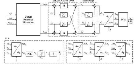
Fig.3 . Overall blog diagram of the unified control strategy.
3.2 CONTROL SCHEME
Fig. 2 describes the overall block diagram for the proposed unified control strategy, where the inductor current iL abc, the utility voltage vg abc, the load voltage vC abc, and the load current iLLabcare sensed. And the three-phase inverter is controlled in the SRF, in which, three phase variable will be represented by dc
quantity. The control diagram is mainly composed by the inductor current loop, the PLL, and the current reference generation module. In the inductor current loop, the PI compensator is employed in both D- and Q-axes, and a decoupling of the cross coupling denoted by ω0Lf/k PWM is implemented in order to mitigate the couplings due to the inductor. The output of the inner current loop ddq , together with the decoupling of the capacitor voltage denoted by 1/kiwi, sets the reference for the standard space vector modulation that controls the switches of the three-phase inverter. It should be noted that kiwi denotes the voltage gain of the inverter, which equals to half of the dc voltage in this paper.
Fig.4 Block Diagram of the current reference generation module.
International Journal of Research (IJR)
e-ISSN: 2348-6848, p- ISSN: 2348-795X Volume 2, Issue 12, December 2015Available at http://internationaljournalofresearch.org
mode. Moreover, the unified load current feed forward, to deal with the nonlinear local load, is also implemented in this module. The block diagram of the proposed current reference generation module is shown in Fig. 19, which provides the current reference for the inner current loop in both grid-tied and islanded modes.
In this module, it can be found that an unsymmetrical structure is used in D- and Q-axes. The PI compensator is adopted in D-axes, while the P compensator is employed in Q-axis. Besides, an extra limiter is added in the D-axis. Moreover, the load current feed forward is implemented by adding the load current iLLdqto the final inductor current reference lire do. The benefit brought by the unique structure in Fig. 3 can be represented by two parts: 1) seamless transfer capability without critical islanding detection; and 2) power quality improvement in both grid-tied and islanded operations. The current reference iLredq composes of four parts in D-and Q-axes respectively: 1) the output of voltage controller irefdq; 2) the grid current reference Igrefdq; 3) the load currentiLLdq; and 4) the current flowing through the filter capacitor Cf. In the grid-tied mode, the load voltage chq is clamped by the utility. The current reference is irrelevant to the load voltage, due to the saturation of the PI compensator in D-axis, and the output of the P compensator being zero in Q-axis, and thus, the inverter operates as a current source. Upon occurrence of islanding, the voltage controller takes over automatically to control the load voltage by regulating the current reference, and the inverter acts as a voltage source to supply stable voltage to the local load; this relieves the need for switching between different controls architectures.
Another distinguished function of the current reference generation module is the load current feed forward. The sensed load current is added as a part of the inductor current reference lire do to compensate the harmonic component in the grid current under nonlinear local load. In the islanded mode, the load current feed forward operates still, and the disturbance from the load
current, caused by the nonlinear load, can be suppressed by the fast inner inductor current loop, and thus, the quality of the load voltage is improved. The inductor current control in Fig. 18 was proposed in previous publications for grid-tied operation of DG [18], and the motivation of this paper is to propose a unified control strategy for DG in both grid-tied and islanded modes, which is represented by the current reference generation module in Fig.
The contribution of this module can be summarized in two aspects. First, by introducing PI compensator and P compensator in D-axis and Q-axis respectively, the voltage controller is inactivated in the grid-tied mode and can be automatically activated upon occurrence of islanding. Therefore, there is no need for switching different controllers or critical islanding detection, and the quality of the load voltage during the transition from the grid-tied mode to the islanded mode can be improved. The second contribution of this module is to present the load current feed forward to deal with the issue caused by the nonlinear local load, with which, not only the waveform of the grid current in grid-tied is improved, but also the quality of the load voltage in the islanded mode is enhanced. Besides, it should be noted that a three-phase unbalanced local load cannot be fed by the DG with the proposed control strategy, because there is no flow path for the zero sequence current of the unbalanced load, and the regulation of the zero sequence current is beyond the scope of the proposed control strategy.
4. FUZZY LOGIC CONTROLLER
International Journal of Research (IJR)
e-ISSN: 2348-6848, p- ISSN: 2348-795X Volume 2, Issue 12, December 2015Available at http://internationaljournalofresearch.org
parameter variations as well as improved transient and steady state performances.
In this study, a fuzzy logic based feedback controller is employed for controlling the voltage injection of the proposed Dynamic Voltage Restorer (DVR). Fuzzy logic controller is preferred over the conventional PI and PID controller because of its robustness to system parameter variations during operation and its simplicity of implementation. Since the proposed DVR uses energy storage system consisting of capacitors charged directly from the supply lines through rectifier and the output of the inverter depends upon the energy stored in the dc link capacitors. But as the amount of energy stored varies with the voltage sag/swell events, the conventional PI and PID controllers are susceptible to these parameter variations of the energy storage system; hence the control of voltage injection becomes difficult. The proposed FLC scheme exploits the simplicity of the Madman type fuzzy systems that are used in the design of the controller and adaptation mechanism.
Figure.5 Schematic representation of Fuzzy Logic Controller
The fuzzy logic based control scheme can be divided into four main functional blocks namely Knowledge base, Fuzzification, Inference mechanism and Defuzzification. The knowledge base is composed of data base and rule base. Data base consists of input and output membership functions and provides information for appropriate fuzzification and defuzzification operations. The rule-base consists of a set of linguistic rules relating the fuzzified input
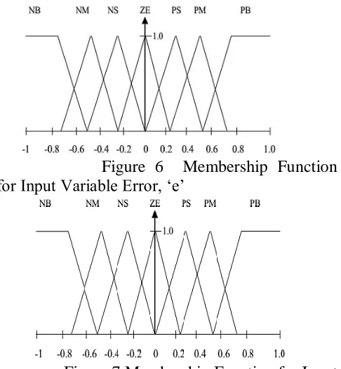
variables to the desired control actions. Fuzzification converts a crisp input signals, error (e), and change in error (ce) into fuzzified signals that can be identified by level of memberships in the fuzzy sets. The inference mechanism uses the collection of linguistic rules to convert the input conditions to fuzzified output. Finally, the defuzzification converts the fuzzified outputs to crisp control signals using the output membership function, which in the system acts as the changes in the control input (u).The typical input membership functions for error and change in error are shown in Fig 6a and Fig 6b respectively, whereas the output membership function for change in control input is shown in Fig 8c. The output generated by fuzzy logic controller must be crisp which is used to control the PWM generation unit and thus accomplished by the defuzzification block. Many defuzzification strategies are available, such as, the weighted average criterion, the mean-max membership, and center-of-area (centroid) method. The defuzzification technique used here is based upon centroid method.
Figure 6 Membership Function for Input Variable Error, „e‟
International Journal of Research (IJR)
e-ISSN: 2348-6848, p- ISSN: 2348-795X Volume 2, Issue 12, December 2015Available at http://internationaljournalofresearch.org
Figure.8 Membership Function for Output Variable Change in Control Signal, „u‟. The set of fuzzy control linguistic rules is given in Table 1. The inference mechanism of fuzzy logic controller utilizes these rules to generate the required output. DVR is generally connected in feeders having sensitive loads whose terminal voltage has to be regulated. The SIMULINK model of proposed fuzzy logic controller is shown in the Fig .
Figure.9 . SIMULINK model of proposed FLC
5. MATLAB MODEL AND
SIMULATION RESULTS
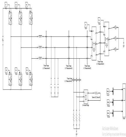
5.1 MATLAB PROPOSED MODELFigure.10 Matlab Model For Proposed Model 5.2. SIMULATION RESULTS
International Journal of Research (IJR)
e-ISSN: 2348-6848, p- ISSN: 2348-795X Volume 2, Issue 12, December 2015Available at http://internationaljournalofresearch.org
(a)
(b)
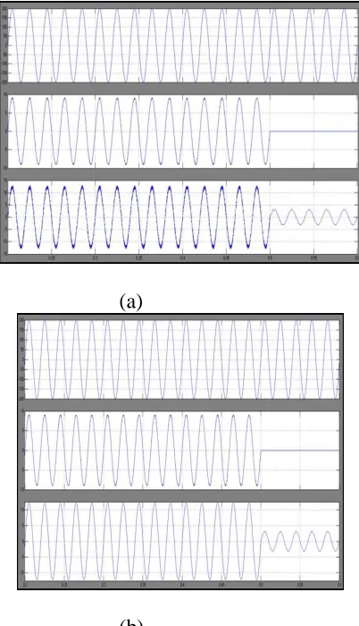
Figure.11 Simulation waveforms of load voltage v Ca, grid current iga, and inductor current iLa when DG is in the grid-tied mode under condition of the step down of the grid current reference from 9 A to 5 A with: (a) conventional voltage mode control, and (b) proposed unified control strategy is 50 Hz,
And the upper and the lower values of the limiter in the PLL are given as 0.2 Hz higher and lower than the rated frequency, respectively.
In the grid-tied mode, the dynamic performance of the conventional voltage mode control and the proposed unified control strategy is compared by stepping down the grid current reference from 9 A to 5 A. The simulation result of the voltage mode control is shown in Fig. .and the current reference is changed at the moment of 14 s. It is found that dynamic process lasts until around 15.2 s. In the proposed unified control strategy, the simulation result is represented in Fig. and the time interval of the dynamic process is less than 5 ms. Comparing
(a)
(b)
Fig. 12 Simulation waveforms of load voltage vCa, grid current iga, and inductor current iLa when DG is transferred from the grid-tied mode to the islanded mode with: (a) conventional hybrid voltage and current mode control, and (b) proposed unified control strategy.
International Journal of Research (IJR)
e-ISSN: 2348-6848, p- ISSN: 2348-795X Volume 2, Issue 12, December 2015Available at http://internationaljournalofresearch.org
zero at 0.5 s, and that the load voltage is seriously distorted from 0.5 to 0.52 s. Then, the load voltage is recovered to the normal value after 0.52 s. Fig. 15(b) presents the simulate results with the proposed unified control strategy. Initially, the magnitude of grid current is 9 A and follows the current reference Igrefdq. The magnitude and frequency of the load voltage are held by the utility. After the islanding happens, the amplitude of the load voltage increases a little to follow the voltage reference Vmax, and the output current of DG decreases autonomously to match the load power demand
6. CONCLUSION
A fuzzy based three-phase inverter for a unified controller in distributed generation with no need for switching between two different control architectures or critical islanding detection. The voltage controller is inactivated in the grid-tied mode, and the DG operates as a current source with fast dynamic performance. Upon the utility outage, the voltage controller can automatically be activated to regulate the load voltage. Moreover, the load current feed forward can improve the waveform quality of both the grid current in the grid-tied mode and the load voltage in the islanded mode. The proposed efficient control strategy was verified by the simulation and experimental results.
7. REFERENCES
[1] R. C. Dugan and T. E. McDermott, “Distributed generation,”IEEE Ind. Appl. Mag., vol. 8, no. 2, pp. 19–25, Mar./Apr. 2002.
[2] R. H. Lasseter, “Microgrids and distributed generation,”J. Energy Eng., vol. 133, no. 3, pp. 144–149, Sep. 2007.
[3] C. Mozina, “Impact of green power distributed generation,” IEEE Ind. Appl. Mag., vol. 16, no. 4, pp. 55–62, Jul./Aug. 2010.
[4] IEEE Recommended Practice for Utility Interface of Photovoltaic(PV) Systems, IEEE Standard 929-2000, 2000.
[5] IEEE Standard for Interconnecting Distributed Resources with Electric Power Systems, IEEE Standard 1547-2003, 2003.
[6] J. Stevens, R. Bonn, J. Ginn, and S. Gonzalez,Development and Testing of an Approach to Anti-Islanding in Utility-Interconnected Photovoltaic Systems. Livermore, CA, USA: Sandia National Laboratories, 2000.
[7] A. M. Massoud, K. H. Ahmed, S. J. Finney, and B. W. Williams, “Harmonic distortion-based island detection technique for inverter-based distributed generation,”IET Renewable Power Gener., vol. 3, no. 4, pp. 493– 507, Dec. 2009.
[8] T. Thacker, R. Burgos, F. Wang, and D. Boroyevich, “Single-phase islanding detection based on phase-locked loop stability,” inProc. 1st IEEE Energy Convers. Congr. Expo., San Jose, CA, USA, 2009, pp. 3371–3377.
[9] S.-K. Kim, J.-H. Jeon, J.-B. Ahn, B. Lee, and S.-H. Kwon, “Frequencyshift acceleration control for anti-islanding of a distributed-generation inverter,” IEEE Trans. Ind. Electron., vol. 57, no. 2, pp. 494–504, Feb 2010.
[10] A. Yafaoui, B. Wu, and S. Kouro, “Improved active frequency drift antiislanding detection method for grid connected photovoltaic systems,” IEEE Trans. Power Electron., vol. 27, no. 5, pp. 2367–2375, May 2012.
[11] J. M. Guerrero, L. Hang, and J. Uceda, “Control of distributed uninterruptible power supply systems,”IEEE Trans. Ind. Electron., vol. 55, no. 8, pp. 2845–2859, Aug. 2008.
International Journal of Research (IJR)
e-ISSN: 2348-6848, p- ISSN: 2348-795X Volume 2, Issue 12, December 2015Available at http://internationaljournalofresearch.org
standalone AC supply systems,”IEEE Trans. Ind. Appl., vol. 29, no. 1, pp. 136–143, Jan./Feb. 1993.
[13] Y. Li, D. M. Vilathgamuwa, and P. C. Loh, “Design, analysis, and realtime testing of a controller for multibus microgrid system,” IEEE Trans. Power Electron., vol. 19, no. 5, pp. 1195– 1204, Sep. 2004.
[14] F. Gao and M. R. Iravani, “A control strategy for a distributed generation unit in grid-connected and autonomous modes of operation,”IEEE Trans. Power Del., vol. 23, no. 2, pp. 850–859, Apr. 2008.
[15] S.-H. Hu, C.-Y. Kuo, T.-L. Lee, and J. M. Guerrero, “Droop-controlled inverters with seamless transition between islanding and grid-connected operations,” inProc. 3rd IEEE Energy Convers. Congr. Expo., Phoenix, AZ, USA, 2011, pp. 2196–2201.
[16] L. Arnedo, S. Dwari, V. Blasko, and S. Park, “80 kW hybrid solar inverter for standalone and grid connected applications,” inProc. 27th IEEE Appl. Power Electron. Conf. Expo., Orlando, FL, USA, 2012, pp. 270– 276.
[17] R. Tirumala, N. Mohan, and C. Henze, “Seamless transfer of gridconnected PWM inverters between utility-interactive and stand-alone modes,” inProc. 17th IEEE Appl. Power Electron. Conf. Expo., Dallas, TX, USA, 2002, pp. 1081–1086.
[18] R. Teodorescu and F. Blaabjerg, “Flexible control of small wind turbines with grid failure detection operating in stand-alone and grid-connected mode,”IEEE Trans. Power Electron., vol. 19, no. 5, pp. 1323–1332, Sep. 2004.
[19] H. Zeineldin, M. I. Marei, E. F. El-Saadany, and M. M. A. Salama, “Safe controlled islanding of inverter based distributed generation,” inProc. 35th IEEE Power Electron. Spec. Conf., Aachen, Germany, 2004, pp. 2515– 2520.
[20] H. Zeineldin, E. F. El-Saadany, and M. M. A. Salama, “Intentional islanding of distributed generation,” in Proc. IEEE Power Eng. Soc. Gen. Meeting, San Francisco, CA, USA, 2005, pp. 1496–1502.