c e-ISSN: 2348-6848, p- ISSN: 2348-795X Volume 2, Issue 12, December 2015
International Journal of Research (IJR)
Available at http://internationaljournalofresearch.orgComparative Analysis using Different Inverter Topologies for
Traction System
V Sandhyarani
M-tech Student ScholarDepartment of Electrical & Electronics Engineering,
ANURAG group of institutions (Formerly CVSR College of Engineering andtechnology) Engineering College,
Ghatkeshar; Rangareddy (Dt); Telangana, India.
B Nageswara Rao
Assistant Professor
Department of Electrical & Electronics Engineering,
ANURAG group of institutions (Formerly CVSR College of Engineering and technology) Engineering College, Ghatkeshar; Rangareddy (Dt); Telangana, India.
Abstract—
The induction motor three phase drive provides an
increase in the overall performance of
electric traction equipment. With the ability to increase the level of the installed power, the train operator has been able to improve train operating times, the speed of the traction unit and the demand on the power supply system. With the introduction of inverter drives it has become necessary to complete a systems approach to ensure the safe operation of existing railway electrification infrastructure, and the safety critical areas of train signaling, and telecommunications. The conventional type of inverter suffers with the shoot through issues to avoid these problems traction drive systems using the Z-source inverter. By controlling the shoot-through duty cycle and modulation index, we can control the drive effectively. With the impedance network, the Z-source inverter can advantageously use the shoot through state to boost voltage. This one-stage power conversion and control system has higher reliability, higher efficiency, and lower cost. These facts make the Z-source inverter desirable for use in hybrid electric vehicles, as the cost and complexity is reduced when compared to the traditional inverters.
Keywords—Z source inverter; locomotives; constant boost control; electric traction
I.INTRODUCTION
Three phase locomotives which are in service today uses AC-DC-AC conversion technology for its speed control. The front end converter is H bridge type to reduce the harmonics injected into the source. Voltage source inverter fed squirrel cage induction motors are being used to drive the locomotive. A novel inverter, Z
source inverter has been designed and
developed which works in buck or boost configuration. The control strategy used for power conversion is
c e-ISSN: 2348-6848, p- ISSN: 2348-795X Volume 2, Issue 12, December 2015
International Journal of Research (IJR)
Available at http://internationaljournalofresearch.orgimpedance source (Z source) inverter is constant boost control with third harmonic injection.
II. TYPES OF INVERTERS
There are three basic types of inverters commonly employed in adjustable AC drives system i) voltage source inverter ii) current source inverter iii) Z-source inverter. The variable voltage inverter (VVI), or square-wave six-step voltage source inverter (VSI), receives DC power from an adjustable voltage source and adjusts the frequency and voltage. The current source inverter (CSI) receives DC power from an adjustable current source and adjusts the frequency and current. Z-source inverter is the combination of voltage Z-source inverter and current source inverter.
A. Voltage-Source Inverter
Fig.1 shows the three-phase voltage-source inverter structure. A DC voltage source supported by a relatively large capacitor feeds the 3-phase inverter circuit. The DC voltage source can be a battery, fuel-cell stack, diode rectifier, and/or capacitor. Six switches are used in the main circuit each is traditionally composed of a power transistor and an anti-parallel (or freewheeling) diode to provide bidirectional current flow and unidirectional voltage blocking capability. It has certain limitation of the voltage source inverter. The AC output voltage is limited below and cannot exceed the DC voltage. The V-source inverter is a buck (step-down) inverter for DC-to-AC power conversion. The upper and lower devices of each phase leg should not be gated on simultaneously because a shoot-through would occur and destroy the devices. The shoot-through problem by electromagnetic interference (EMI) noise’s misgating-on is a major killer to the converter’s reliability.
Fig.1. Voltage-source inverter
B. Current-Source Inverter
Fig.2 shows the three-phase current-source inverter structure. A DC current source feeds the 3-phase
inverter circuit. The DC current source can be a relatively large DC inductor fed by a voltage source such as a battery, fuel-cell stack, diode rectifier, or thyristor converter. Six switches are used in the main
circuit each is traditionally composed of a
semiconductor switching device with reverse block capability such as a gate-turn-off thyristor (GTO) and SCR or a power transistor with a series diode to provide unidirectional current flow and bidirectional voltage blocking.
The current source inverter has certain Limitations of the AC output voltage has to be greater than the original DC voltage that feeds the DC inductor or the DC voltage produced is always smaller than the AC input voltage. The I-source inverter is a boost inverter for DC-to-AC power conversion. At least one of the upper devices and one of the lower devices have to be gated on and maintained on at any time. Otherwise, an open circuit of the DC inductor would occur and destroy the devices. The open-circuit problem by EMI noise’s misgating-off is a major concern of the inverters reliability. The main switches of the I-source inverter have to block reverse voltage that requires a series diode to be used in combination with high-speed and high performance transistors such as insulated gate bipolar transistors (IGBTs). This prevents the direct use of low-cost and high-performance IGBT modules and intelligent power modules (IPMs).
Fig.2. Current-source inverter
C. Z-Source Inverter
c e-ISSN: 2348-6848, p- ISSN: 2348-795X Volume 2, Issue 12, December 2015
International Journal of Research (IJR)
Available at http://internationaljournalofresearch.orgsource inverter intentionally utilizes the shoot through zero states to boost DC voltage and produce an output voltage greater than the original DC voltage .At the same time, the Z-source structure enhances the reliability of the inverter greatly because the shoot through states that might be caused by EMI noise can no longer destroy the inverter. For the traditional V-source inverter, the DC capacitor is the sole energy storage and filtering element to suppress voltage ripple and serve temporary storage. For the traditional I source Inverter, the DC inductor is the sole energy storage/filtering element to suppress current ripple and serve temporary storage.
Fig.3. General Structure of the Z-Source inverter
The Z-source network is a combination of two inductors and two capacitors. This combined circuit, the Z-source network is the energy storage/filtering element for the Z-source inverter. The Z-source network provides a second order filter and is more effective to suppress voltage and current ripples than capacitor or inductor used alone in the traditional inverters. Therefore, the inductor and capacitor requirement should be smaller than the traditional inverters. The Unique features of Z-source inverter are i) it’s the buck boost function by one stage conversion. ii) Immunity to EMI noise and misgating (i.e., misgating on and off by EMI noise will not destroy the inverter).iii) Low or no in-rush current compared with the V-inverter and has low common mode noise.
III. INDUCTION MOTOR
The AC induction motor is considered since its discovery as actuator privileged in the applications of constant speed, and it has many advantages, such as low cost, high efficiency, good self starting, its simplicity of design, the absence of the collector brooms system, and a small inertia. The induction motor is a rotating electric machine designed to operate from a 3-phase source of alternating voltage. For variable speed drives, the source is normally an inverter that uses power switches to produce approximately sinusoidal voltages and currents of controllable magnitude and frequency. A cross section of a two-pole induction motor is shown in Figure 4
Fig.4 cross-section of induction motor
c e-ISSN: 2348-6848, p- ISSN: 2348-795X Volume 2, Issue 12, December 2015
International Journal of Research (IJR)
Available at http://internationaljournalofresearch.orgFig.5 Induction Motor Speed-Torque Characteristics
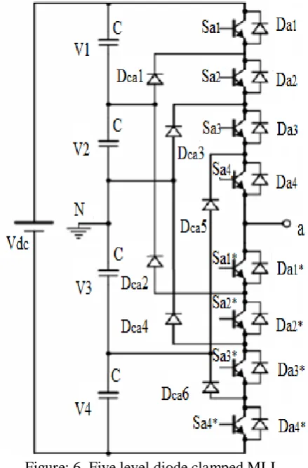
IV. DIODE-CLAMPED MULTILEVEL INVERTER (DCMI)
To explain how the staircase voltage is synthesized, point O is considered as the output phase voltage reference point. Using the five-level inverter shown in Fig. 4.13, there are five switch combinations to generate five level voltages across A and O. Table 4.1 shows the phase voltage level and their corresponding switch states.
The diode-clamped inverter was also called the neutral-point clamped (NPC) inverter when it was first used in a three-level inverter in which the mid-voltage level was defined as the neutral point. The diode-clamped multilevel inverter uses capacitors in series to divide up the dc bus voltage into a set of voltage levels. To produce m levels of the phase voltage, an m level diode-clamp inverter needs m-1 capacitors on the dc bus. A single-phase five-level diode-clamped inverter is shown in Fig. 4.13. The dc bus consists of four capacitors, i.e., C1, C2, C3, and C4. For a dc bus voltage Vdc, the voltage across each capacitor is Vdc/4, and each device voltage stress will be limited to one capacitor voltage level, Vdc/4, through clamping diodes. DCMI output voltage synthesis is relatively straightforward.
Figure: 6. Five level diode clamped MLI
Output VAO
Switch states
Sa1 Sa2 Sa3 Sa4 Sa1* Sa2* Sa*’ Sa4*
V5=Vdc 1 1 1 1 0 0 0 0
V4=3Vdc /4 0 1 1 1 1 0 0 0
V3=Vdc/2 0 0 1 1 1 1 0 0
V2=Vdc/4 0 0 0 1 1 1 1 0
V1=0. 0 0 0 0 1 1 1 1
Table: 1 Diode-clamped five-level inverter voltage levels and their switch states
V.SYTEM DESCRIPTION
c e-ISSN: 2348-6848, p- ISSN: 2348-795X Volume 2, Issue 12, December 2015
International Journal of Research (IJR)
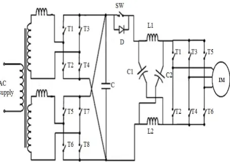
Available at http://internationaljournalofresearch.orgtransformer has four secondary windings, each of which is connected to AC-DC converter. Two converters are connected in H bridge topology and the outputs of the converters are fed to the z source inverters through the dc link. There are six motors grouped in to two, each contains three parallel connected traction motors. The schematic and power circuit diagram of ZSI fed locomotive drive is given in fig.1-2
Figure 1 Schematic diagram of locomotive fed by impedance source inverter
Figure 2 Power circuit of one group of ZSI fed traction motor drive
The stator reference frame model differential equations of induction motor in matrix form [9] is given by equation (1)
(1)
(2) Where Rs and Rr are the stator and rotor resistances, Ls, Lr and Lm represent the stator, rotor and magnetizing inductances indicated the differential operator d/dt, ωr the speed of rotor in rad/s. Vqs ,Vds,Vqr,Vdr represents the quadrature and direct axes voltages of stator and rotor respectively, iqs, ids, iqr and idr are the quadrature and direct axes currents of stator and rotor respectively. The electromagnetic torque is given by equation (2) where P represents the number of poles. The control strategy for Z source inverter adopted is constant boost control with third harmonic injection [3].
A. Control topology
In this topology, 1/6th of the third harmonic is added with the fundamental signal to get the modulating wave. It is compared with the triangular carrier wave to get the switching signals for the non shoot through period. The pulses for shoot through period are obtained by comparing two straight lines with triangular carrier signal. When the straight line is less than or greater than the carrier wave, shoot through pulses are generated.
The voltage gain is given by
(3) The boost factor, B is given by
(4) The voltage stress, Vs is given by
(5) Where is the dc voltage at the input of ZSI, to be the
shoot through period in a switching cycle T, Vs is the
c e-ISSN: 2348-6848, p- ISSN: 2348-795X Volume 2, Issue 12, December 2015
International Journal of Research (IJR)
Available at http://internationaljournalofresearch.orgthe constant torque mode. The schematic of pulse generation by open loop v/f law for constant boost controlled Z source inverter fed traction motor is given in fig.3 The value of modulation index for a particular frequency, f is determined from the equation (6)
(6) The single phase front end converter is capable of maintaining constant dc voltage and input power factor at unity. The schematic of the inner current loop and outer voltage loop is given in fig.4 and fig.5 respectively.
Figure 3 Schematic of pulse generator for inverter
Figure 4 Schematic of current loop for front end converter
Figure 5 Schematic of voltage loop for front end converter
B. Design of impedance network parameters
The value of inductance and capacitance are calculated using the parameters of traction motors used in three phase locomotives [11].
(7)
(8) Where M is the modulation index and ki , kv represent current ripple and voltage ripple respectively.
VI. SIMULATION RESULTS AND DISCUSSION
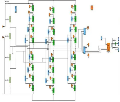
The z source inverter fed locomotive drive is modelled and simulated in MATLAB/Simulink. The stator current, speed of the motor and torque for rated load are plotted
Fig.6 mat lab/Simulink model of five level diode clamped inverter fed to induction motor
c e-ISSN: 2348-6848, p- ISSN: 2348-795X Volume 2, Issue 12, December 2015
International Journal of Research (IJR)
Available at http://internationaljournalofresearch.orgFigure: 8 Simulink diagram 5 level Inverter Output Voltage without z source
Figure 9 Simulink diagram of with z source inverter fed by locomotive drive
Figure 10. Simulink diagram of proposed with z source inverter fed by locomotive drive
Figure: 11.Simulink diagram of proposed without z source inverter fed by locomotive drive
Figure: 12.complete Simulink diagram of proposed with z source inverter fed by locomotive drive
c e-ISSN: 2348-6848, p- ISSN: 2348-795X Volume 2, Issue 12, December 2015
International Journal of Research (IJR)
Available at http://internationaljournalofresearch.orgFigure: 14 Performance Characteristics of Induction Motor At full load torque = 50 N-m and speed=1800 rpm Without Multilevel inverter
Figure: 15 Proposed Performance Characteristics of Induction Motor At 3/4th
load torque = 37 N-m and speed=1800 rpm With Multilevel inverter
Figure: 16 Performance Characteristics of Induction Motor At 3/4thload
torque = 37 N-m and speed=1800 rpm Without Multilevel inverter
Figure: 17 Proposed Performance Characteristics of Induction Motor At half load torque = 25N-m and speed=1800 rpm With Multilevel inverter
Figure: 18 Performance Characteristics of Induction Motor At half load torque = 25 N-m and speed=1800 rpm Without Multilevel inverter
c e-ISSN: 2348-6848, p- ISSN: 2348-795X Volume 2, Issue 12, December 2015
International Journal of Research (IJR)
Available at http://internationaljournalofresearch.orgFigure: 20.Thd of Voltage with Z Source Inverter without Multilevel
inverter
Figure: 21.Thd of Voltage without Z Source Inverter with multi level inverter
Figure: 22.Thd of Current without Z Source Inverter
Table2: Inverter output voltage THD at different load conditions At speed=1800rpm
Table3: Stator current THD at different load conditions At speed=1800rpm
IV. CONCLUSION
c e-ISSN: 2348-6848, p- ISSN: 2348-795X Volume 2, Issue 12, December 2015
International Journal of Research (IJR)
Available at http://internationaljournalofresearch.orgREFERENCES
[1] Zheng Peng” Z-Source Inverter” IEEE
TRANSACTIONS ON INDUSTRY APPLICATIONS, VOL. 39, NO. 2, MARCH/APRIL 2003
[2] Fang Zheng Peng, , Miaosen Shen, and Zhaoming Qian,” Maximum Boost Control of the Z-Source Inverter” IEEE TRANSACTIONS ON POWER ELECTRONICS, VOL. 20, NO. 4, JULY 2005
[3] Zheng Peng” Z-Source Inverter” IEEE
TRANSACTIONS ON INDUSTRY APPLICATIONS, VOL. 39, NO. 2, MARCH/APRIL 2003
[4] Fang Zheng Peng, , Miaosen Shen, and Zhaoming Qian,” Maximum Boost Control of the Z-Source Inverter” IEEE TRANSACTIONS ON POWER ELECTRONICS, VOL. 20, NO. 4, JULY 2005
[5] M. Shen, J. Wang, A. Joseph, F. Z. Peng, L. M. Tolbert and D. J. Adams,“Constant boost control of the Z-source inverter to minimize current ripple and voltage stress,” IEEE Transactions on Industry Applications, Vol. 42, No. 3, pp. 770-778, May 2006.
[6] S. Yang, X. Ding, F. Z. Peng, and F. Z. Z. Qian, “Unified control
technique for Z-s urce inverter,” Proceedings. IEEE – PESC 2008, pp. 3236 – 3242, Jun. 2008.
[7] Q. V. Tran, T. W. Chun, J. R. Ahn and H. H. Lee, “Algorithms
for controlling both the DC boost and AC output voltage of Z-source inverter,” IEEE Transactions on Industrial Electronics, Vol. 54, No. 5,pp. 2745-2750, Oct. 2007.
[8] P. C. Loh, M. Vilathgamuwa, Y. S. Lai, G. T. Chua and Y. W. Li, “Pulse width modulation of Z-source inverters,” IEEE Transactions on Power Electronics, Vol. 20, No. 6, pp.1346-1355, Nov. 2005.
[9] Fang Zheng Peng, Alan Joseph, JinWang, Miaosen Shen, Lihua Chen, Zhiguo PanEduardo Ortiz-Rivera, and Yi Huang,” Z-Source Inverter for Motor Drives”,
IEEE TRANSACTIONS ON POWER
ELECTRONICS, VOL. 20, NO. 4, JULY 2005
[10] Omar Ellabban, Joeri Van Mierlo, Philippe Lataire1 and Peter Van den Bossche” Z-Source Inverter for Vehicular Applications “Vehicle Power and Propulsion Conf. 2011 IEEE
[11] Haping Xu,Fang Z Peng, Lihua Chen, Xuhui wen,”Analysis and design of Bi-directional Z source inverter for electrical ehicles”2008,IEEE