REDESIGN AND OPTIMIZATION OF KEYSEAT
HILMAN MUTTAQIN
REDESIGN, OPTIMIZATION AND VALIDATION OF KEYSEAT
HILMAN MUTTAQIN
A project report submitted in partial fulfillment of the requirements for the award of the degree of
Master of Computer Science (Information Technology - Manufacturing)
Faculty of Computer Science and Information Systems Universiti Teknologi Malaysia
v
ABSTRACT
vi
ABSTRAK
vii
TABLE OF CONTENTS
CHAPTER TITLE PAGE
DECLARATION DEDICATION
ACKNOWLEDGEMENTS ABSTRACT
ABSTRAK
TABLE OF CONTENTS LIST OF TABLES LIST OF FIGURES LIST OF SYMBOLS
ii iv v vi vii vii xi xii xiii
1 PROJECT OVERVIEW
1.1 Introduction
1.2 Background of Problem 1.3 Statement of the Problem 1.4 Project Objectives 1.5 Scope of Study
1.6 Organization of the Report
1 1 3 3 4 4 4
2 LITERATURE REVIEW
2.1 Keyseat 2.1.1 Keyway 2.1.2 Key
viii
2.2 Mathematic Analysis 2.2.1 Key Size 2.2.2 Strength of Key 2.2.3 Crushing Strength 2.2.4 Stress in Key 2.2.5 Material of Key 2.2.6 Design of Key 2.3 Design Tool
2.3.1 Computer-Aided Design (CAD) 2.3.2 Computer-Aided Engineering (CAE) 2.3.3 Computer-Aided Manufacturing (CAM) 2.4 Simulation
2.5 Real Manufacturing 2.6 G-Code 2.7 Optimization 2.8 Validation 10 11 16 18 18 19 20 21 22 23 23 25 25 28 29 30 3 METHODOLOGY 3.1 Problem Identification 3.2 Data Collection
3.2.1 Design
3.2.2 Mathematic Analysis 3.2.3 Simulation
3.2.4 Real Manufacturing 3.3 Step Taken
3.4 Test and Validation 3.5 Implementation 3.5.1 Software 3.5.2 Hardware 34 34 34 34 35 35 35 36 37 37 37 38
4 THE MODELING AND SIMULATION
4.1 Original Model 4.2 Redesign Model
ix
4.3 Calculation
4.3.1 Keyseat Size 4.3.2 Lathe Calculation 4.3.3 Millng Calculation 4.4 Design Tools Interface 4.5 Simulation
4.5.1 Backplot Selected Operation 4.5.2 Verify Selected Operation 4.5.3 First Keyseat Simulation 4.6 G-Code
4.6.1 Lathe G-Code
4.6.2 First Keyseat G-Code 4.6.3 Second Keyseat G-Code 4.7 Keyways Calculation Program
4.7.1 Interface 43 43 44 48 50 52 52 53 54 56 56 59 60 61 61
5 VALIDATION AND RESULT ANALYSIS 5.1 Dimension
5.1.1 First Keyseat 5.1.2 Second Keyseat 5.2 Time
5.3 NC Code
5.3.1 Lathe G Code 5.3.2 Keyseat G Code
64 68 68 69 69 71 71 71
6 DISCUSSION AND CONCLUSION
x
LIST OF TABLES
TABEL NO. TITLE PAGE
2.1 2.2 2.3 2.4 2.5 2.6 4.1 4.2 4.3 4.4 5.1 5.2 5.3 5.4 5.5 5.6
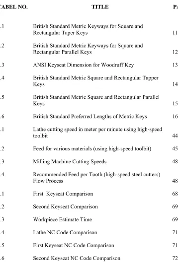
British Standard Metric Keyways for Square and Rectangular Taper Keys
British Standard Metric Keyways for Square and Rectangular Parallel Keys
ANSI Keyseat Dimension for Woodruff Key
British Standard Metric Square and Rectangular Tapper Keys
British Standard Metric Square and Rectangular Parallel Keys
British Standard Preferred Lengths of Metric Keys Lathe cutting speed in meter per minute using high-speed toolbit
Feed for various materials (using high-speed toolbit) Milling Machine Cutting Speeds
Recommended Feed per Tooth (high-speed steel cutters) Flow Process
First Keyseat Comparison Second Keyseat Comparison Workpiece Estimate Time Lathe NC Code Comparison
First Keyseat NC Code Comparison Second Keyseat NC Code Comparison
xi
LIST OF FIGURES
FIGURE NO. TITLE PAGE
1.1 2.1 2.2 2.3 2.4 2.5 2.6 2.7 2.8 2.9 2.10 2.11 3.1 4.1 4.2 4.3 4.4 4.5 4.6 4.7 4.8 4.9 4.10 Broken Keyway Parallel Key Gib Tapper Key Plain Tapper Key Woodruff Key Round Key
Pressure Between Key and Keyseat Force Distributed in Key
HAAS CNC turning / lathe machine CNC Jr. 3 Axis Milling Machine
Design and Documentation Requirements for Full Life Cycle and Standard Validation
Validation Documentation Relation and Sequence Flow Chart of Research Methodology
Original Design
Redesign with Solid Modelling First Keyseat
Second Keyseat Lathe Cutting Step MasterCAM Interface SolidWork Interface
xii 4.11 4.12 4.13 4.14 4.15 4.16 4.17 5.1 5.2 5.3 5.4 5.5 5.6 5.7 5.8 5.9
First Keyseat Simulation Process Second Keyseat Simulation Process Index Program Interface
Keyseat Calculation Program Keyseat Calculation Program Result Milling Calculation Program
Milling Calculation Program Result Flow Process
Original Design
New Design in SolidWorks New Design in MasterCAM Real Manufacturing Product Shaft and Keyslot
Pulley and Keyway Key
Time Machine Estimate
xiii
LIST OF SYMBOLS
D / d - Diameter L - Length of key h - Thickness of key b - Width of key
Ac - Area resisting crushing As - Area resisting shear
Fc - Allowable average crushing stress Fs - Allowable average shear stress P - Tangential pressure
M1 - Torque Txy - Average stress
CHAPTER 1
PROJECT OVERVIEW
1.1 Introduction
Function of keyseat is to lock between main component and sub component
like shaft and gear in transmission. Keyseat as one part of moving machine’s
component need a precision calculation in design, as the move machine component,
keyseat is moving with a main component and distribute the torque, that is the reason
why keyseat need precise design and accurate calculation to decrease wear, noise and
deflation of torque. Without this condition keyseat can make main component failure
and reduce the torque that distributed.
In this era, machine design` is more complicated and more complex and
detail, like sizing, scale, system drawing (America or Europe) and material contour
for each detail design. Designer generally using three types of software design, such
as: Computer-Aided Design (CAD), Computer-Aided Engineering (CAE), and
Computer-Aided Manufacturing (CAM). Software design that usually used like
AutoCAD and Mechanical Desktop are registered trademarks of Autodesk,
SolidWork and CATIA are registered trademarks of Dassault Systemes, and
MasterCAM are registered trademarks of CNC Software, Inc.
Machine design deals with the creation of machinery that works safely,
reliably and well and designer have to know about mechanics, thermodynamics, heat
2
goal in machine design is to size and shape the parts and choose appropriate material
and manufacturing processes so that the resulting machine can be expected to
perform its intended function without failure.
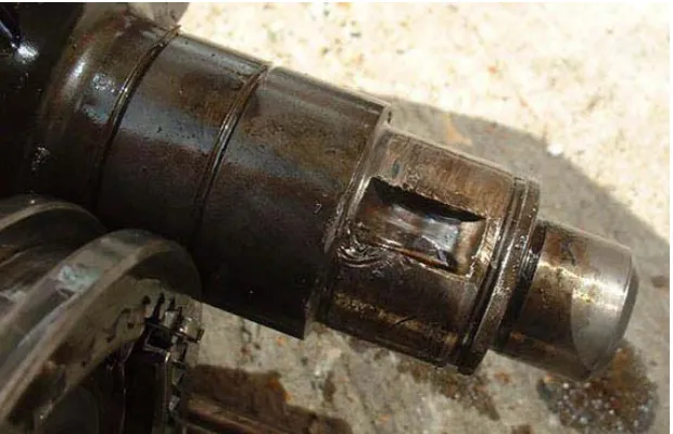
Figure 1.1: Broken Keyway
http://www.phattransmissions.com/200SXWiki/index.php?pagename=Main.Mainsha
ftCounterDrive)
Machining design also have simulation process to simulate a real
manufacturing that refer to what happens when a digital computer runs a state
transition table that describes the state transitions, inputs and outputs of a subject
discrete-state machine. For simulation processes, designer using CAM software
design.
The last process is machining process; machining operations can be divided
into those that remove metal from an item, and those that form metal in an item.
There is many machining operation like Drill, Lathe, Mill, etc, according to
machining processes need. At this time, machining process already uses Computer
3
1.2 Background of Problem
To design part of machine is complicated and have to considerate with
concept generation, product planning, advance engineering, product engineering,
process engineering and pilot running. US concept that usually used in Asia took 26
months to advance engineering schedule and for Europe and Japan concept used 14
and 15 months to advance engineering schedule.
If advance engineering schedule time can be reduce, the designing process
can shorter and can concentrate to another process to increase the quality of product
and decrease production cost.
Keyseat is a small thing in machine component however keyseat need
precision design and correct calculation to design a keyseat because keyseat is
moving part of machine and used to lock and to continue torque from main machine
component to sub main component.
1.3 Problem Statement
Design a keyseat with accurate calculation and analysis is complicate and has
many considerations, for this reason a program that use to make keyseat in machine
design with mathematic calculation, solid modelling and Simulation is needed
According for statement above, this thesis studying as title “Redesign,
4
1.4 Project Objectives
This study was undertaken to achieve the following objectives:
1. Redesign the keyseat
2. To optimize parameter values
3. To validate the value using mathematical calculation and simulation
1.5 Scope of Study
This study was undertaken to achieve the following scope:
1. The design took from anonymous design and keyseat design make under
reflection from literature review.
2. Redesign, simulation and real manufacturing of the product
3. Software modeling is using SolidWork, simulation software is using
MasterCAM and real manufacturing is using CNC machine.
4. Keyseat parameter base on British Standard, BS 4235:Part 1:1972 (1986)
1.6 Paper Overview
Chapter 1 illustrate an introduction and brief overview of the project
including the problem background, problem statement, objectives, and scope.
Chapter 2 explain the literature review; explain about keyseat, formula for
mathematic analysis, design and real machining process.
Chapter 3 covers the methodology of the process that will be use in redesign
process in chapter four for optimization of keyseat.
5
Chapter 5 discuss the validation and result for keyseat after redesign
Chapter 6 the conclusion of the project based on the five previous chapters
that have been discussed.