ISSN (Print) : 2320 – 3765 ISSN (Online): 2278 – 8875
I
nternational
J
ournal of
A
dvanced
R
esearch in
E
lectrical,
E
lectronics and
I
nstrumentation
E
ngineering
(A High Impact Factor, Monthly, Peer Reviewed Journal)
Website: www.ijareeie.com
Vol. 7, Issue 2, February 2018
Control & Implementation of Fuzzy Based
DFIG Wind Power Generators in Unbalanced
Micro grids
P R. Murali Mohan1, K. Sree Hari2
Associate Prof., Dept. of EEE, SVCET, Chittoor, Andhra Pradesh, India1
PG Scholar, Dept. of EEE, SVCET, Chittoor, Andhra Pradesh, India2
ABSTRACT: In the last 15 years, Double Fed Induction Generator (DFIG) had been widely used as a wind turbine generator, due its various advantages especially low generation cost so it becomes the most important and promising sources of renewable energy. This paper presents new control approach for a doubly-fed induction generator (DFIG) wind energy system in an unbalanced micro grid based on fuzzy logic controller. The proposed fuzzy logic controller model uses instantaneous real/reactive power components as the system state variables. This work focuses on studying of using DFIG as a wind turbine connected to a micro grid subjected to unbalanced loads. Furthermore the control of real/reactive powers, the controllers uses the rotor-side converter for mitigating the torque and reactive power pulsations. The control scheme also uses the grid-side converter for partial compensation of unbalanced stator voltage. The main features of the proposed control method are its feedback variables are independent of reference frame transformations and it does not require sequential decomposition of current components. These features simplify the structure of required controllers under an unbalanced voltage condition and inherently improve the robustness of the controllers. A power limiting algorithm is also introduced to protect power converters against over rating and define the priority of real/reactive power references within the control scheme. The performance of the proposed strategy in reducing torque ripples and unbalanced stator voltage is investigated based on the time-domain simulation of a DFIG study system under unbalanced grid voltage.
KEYWORDS: Doubly-fed induction generator, instantaneous power, micro grids, unbalanced grid voltage, wind energy.
I.INTRODUCTION
Wind power generation industry has become widely used in the last few years and takes more attention of manufactures. There are many reasons for adding more wind energy to the electric networks. For instance, wind generation is supported by not only being clean and renewable but also having minimal running cost requirements. Variable speed wind turbine topologies include many different generator/converter configurations, based on cost, efficiency, annual energy capturing, and control complexity of the overall system.
ISSN (Print) : 2320 – 3765 ISSN (Online): 2278 – 8875
I
nternational
J
ournal of
A
dvanced
R
esearch in
E
lectrical,
E
lectronics and
I
nstrumentation
E
ngineering
(A High Impact Factor, Monthly, Peer Reviewed Journal)
Website: www.ijareeie.com
Vol. 7, Issue 2, February 2018
Doubly-fed induction generators (DFIGs) in high-power wind turbine-generators (WTGs) are operational as distributed generators (DGs) units in micro grids. Recent grid codes require a WTG remains operational during transient and steady-state unbalanced grid voltages [1], [2]. A voltage unbalance can steadily exist in a micro grid due to unequal impedance of distribution lines; nonlinear loads such as arc furnaces; and unequal distributions of single-phase loads. Shahnia et al. in [3] propose a distributed intelligent residential load transfer scheme to dynamically reduce voltage unbalance along low voltage distribution feeders. However, due to using widely distributed and variable loads such as single-phase motors, and nonlinear loads in a micro grid, the voltage unbalance condition cannot be completely mitigated. On the other hand, even a small amount of voltage unbalance can cause notable current unbalance in a DFIG. This current unbalance causes torque pulsations and overheating of the machine windings which eventually reduce the lifetime of a DFIG-based WTG in a micro grid [4]–[6].
Modeling and vector control of DFIG-based wind turbine under unbalanced conditions in micro grids are widely addressed in literature [7]–[11]. The existing unbalanced vector control schemes for DGs conventionally use two pairs of individual controllers for the positive and negative sequence components of unbalanced currents [12]–[15]. Tuning of these controllers due to the delays of the decomposing positive/negative sequences filters often requires complex algorithms in unbalanced vector control schemes [14], [15].
Alternative methods have been introduced which directly process the unbalanced rotor current without decomposition into positive/negative sequences [7], [8] and [16], [17]. However, in these methods, the calculation of current references based on the power pulsations also requires the positive and negative sequence components of the machine stator voltage, current, and flux. Direct power control (DPC) methods have been also suggested for unbalanced voltage condition which relatively reduce the complexity of the control method compared to the vector control scheme [11], [18]–[20]. However, the DPC methods similar to the unbalanced vector control methods still need decomposition of positive/negative sequences and compensation for the filters delays.
This paper presents a control method for a DFIG connected to an unbalanced grid voltage, which uses the instantaneous real/reactive powers as the state variables. The proposed control approach offers a robust structure since its state variables are independent of the positive/negative sequences of the DFIG current components. The suggested control scheme also reduces the DFIG torque/power pulsations by using the real/reactive power commands of the rotor-side converters in a DFIG wind energy system. Furthermore, at low wind speed and high unbalanced grid voltage conditions, the excess capacity of grid-side converter can be used for partial compensation of unbalanced stator voltage.
Two current/power limiting algorithms are also introduced for both rotor- and grid-side converters to avoid over rating of the converters. The performance of the proposed method under unbalanced grid voltage condition is investigated via time-domain simulation of a MW-scale DFIG wind turbine-generator study system in which a single-phase load is used to impose a steady voltage unbalance to the micro grid.
II. CONVENTIONAL VECTOR CONTROL SCHEME FOR DFIG SYSTEM
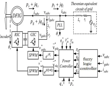
Fig. 1. Schematic diagram of DFIG-based Wind Generation System.
ISSN (Print) : 2320 – 3765 ISSN (Online): 2278 – 8875
I
nternational
J
ournal of
A
dvanced
R
esearch in
E
lectrical,
E
lectronics and
I
nstrumentation
E
ngineering
(A High Impact Factor, Monthly, Peer Reviewed Journal)
Website: www.ijareeie.com
Vol. 7, Issue 2, February 2018
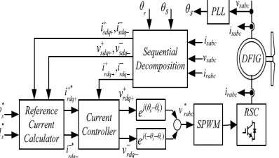
other design techniques such as resonance controller and direct power control using instantaneous power model of the DFIG [17], [21]. However, under unbalanced voltage condition, auxiliary control loops using negative sequences quantities must be added to the conventional vector speed controllers which form an extended unbalanced vector control scheme [7], [17].Figure 2 shows details of the unbalanced vector control scheme for the rotor-side converter [12], [13]. This control strategy mitigates the torque pulsations and the grid unbalanced effects on the generator via independent control of the stator real/reactive power components, p∗
s and q∗s. The sequential decomposition unit in Fig.
2 calculates the positive/negative sequence components in positive /negative sequence qd reference frame. The output of this unit are denoted by f+/−+/− where f represents the voltage or current quantities; superscripts identify +/- sequence
reference frame; and subscripts represent +/- sequence components. In Fig. 2, the +/- reference frame transformations are realized by ej(θs−θr)andej(−
θ
s−θr).
As shown in Fig. 2, the unbalanced vector control method is established based on decompensation of the positive and negative sequences of the rotor current. Practically, this decomposition can be realized by transferring the current to the synchronous reference frame and using digital filters, or signal delay cancelation technique. These methods introduce time delays and obvious errors in amplitude and phase which adversely affect on the dynamic performance of the control system [20].
Recently, alternative methods such as the Proportional Integral Resonant (PIR) controller [7], [8] and the main and auxiliary controllers [16] have been introduced which directly process the unbalanced rotor current without decomposition into positive/negative sequences. In these methods, the current references are calculated according to the power pulsations in a feed-forward manner so the stator voltage, current, and flux have to be decomposed into the positive and negative sequences for calculating the rotor current references [20].
III. PROPOSED FUZZY LOGIC CONTROLLER FOR UNBALANCED VOLTAGE CONDITIONS
In the proposed method, the rotor-side converter in Fig. 1 can be used for the mitigation of the torque and stator reactive power pulsations. Also, the grid-side converter can be used for reduction of unbalanced stator voltage. In the proposed control method, the feedback loops are developed based on instantaneous real/reactive power components which can be directly calculated in abc frame and used in any other reference frame. In the following, first the instantaneous power model of a DFIG is explained and then the details of the proposed control strategy are explained within the following sections.
Fig. 2.Schematic diagram of the conventional unbalanced vector control scheme for DFIG.
ISSN (Print) : 2320 – 3765 ISSN (Online): 2278 – 8875
I
nternational
J
ournal of
A
dvanced
R
esearch in
E
lectrical,
E
lectronics and
I
nstrumentation
E
ngineering
(A High Impact Factor, Monthly, Peer Reviewed Journal)
Website: www.ijareeie.com
Vol. 7, Issue 2, February 2018
A. Instantaneous Power Model of a DFIG
The model of the induction machine in terms of the stator real/reactive power components, psandqs, is [21]:
where details of urd,rq and g1 to g7 are given in Appendix. The grid-side converter and filter model in terms of
instantaneous real and reactive power of grid-side converter, pg and qg, is [22]:
Where
= | |− + (3)
And
= − (4) The dynamic model of the dc link is:
= = (5)
where the real power delivered to the rotor, pr, is:
= + (6) Equations (1)-(6) summarize the model of a DFIG wind power system including the machine and converters.
B. Compensation of Unbalanced Voltage Using GSC
The excess capacity of grid-side converter at low wind speed can be used for a partial compensation of unbalanced stator voltage. This can be achieved through the control of the real/reactive power in GSC corresponding to the negative sequence of the grid voltage. This section develops the mathematical relationship between the power pulsation and the negative sequence voltage which is required in the design procedure of the control system.
The current/voltage vectors can be expressed in terms of their sequence components in +/- synchronous reference frames as:
= + = + − (7)
Based on (7), the instantaneous real/reactive power components can be obtained via definition of complex power as:
( ) = ( ) + ( ) =3
2 3
2 + − + −
= + + ( + − + − +
(8)
where represents the complex conjugate of ̅. Substituting for −̅
gdq− = ˆ_i+gdq−ej2ωetand −sdq− = _v+sdq−ej2ωetin the last
term of (8), we can express complex power in terms of its average and ac components as s = sg,ave+ sg,acwhere:
. = . + .
≜3
ISSN (Print) : 2320 – 3765 ISSN (Online): 2278 – 8875
I
nternational
J
ournal of
A
dvanced
R
esearch in
E
lectrical,
E
lectronics and
I
nstrumentation
E
ngineering
(A High Impact Factor, Monthly, Peer Reviewed Journal)
Website: www.ijareeie.com
Vol. 7, Issue 2, February 2018
. = . + .
≜3
2 + (10)
Based on (10), control of power pulsations (pg,acandqg,ac) via grid-side converter can indirectly compensate unbalanced voltage by reducing +sdq−. To design power pulsation controllers, we start with the model of the grid-side
converter and network in the positive synchronous reference frame as:
−
= + + ( )
− = + + ( )
=− − (12)
To obtain the power model for the negative sequence model, the negative sequence power components in the positive sequence reference frame are defined as:
∆ + =3
2 + (14)
∆ + =3
2 + (15)
By separating positive and negative sequences in (11)-(13) and using (14) and (15) to substitute for_i+sdq−and_i+gdq− in
(11)-(13) and re-arranging the equation, we deduce:
where the p+s−,q+s− are obtained from the negative sequence model of DFIG extracted from (1) in the positive sequence
reference frame and
[ ] =
− [ ] (17)
ISSN (Print) : 2320 – 3765 ISSN (Online): 2278 – 8875
I
nternational
J
ournal of
A
dvanced
R
esearch in
E
lectrical,
E
lectronics and
I
nstrumentation
E
ngineering
(A High Impact Factor, Monthly, Peer Reviewed Journal)
Website: www.ijareeie.com
Vol. 7, Issue 2, February 2018
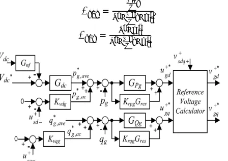
Figure 3 shows the schematic diagram of the grid side converter model and DFIG in terms of power components based on (1) and (16)-(22). In this model, power pulsation references for GSC are used for adjusting the negative sequence grid voltage.
[ ] =
− [ ] (18)
Let the output variables u+sq− and u+sd− are defined corresponding to the negative sequence of the stator voltage as:
[ ] =
− [ ] (19)
Then, by substituting for_i+gdq− in terms of power components from (14) in (12), we deduce:
[ −] =[ ]+
−
[
−]+ [
\
\
] (20
Finally, to associate the negative sequence power components with the power pulsations, the new disturbance terms
sgc, pgc and qgcare defined as:
= + ≜ (21) Thus, based on (10), (14), and (21), we deduce:
, = + , , = + (22)
The resonant compensator (Gres) tuned at the double frequency of the grid which is implemented in the positive sequence reference frame. The notch filter Gnfis also used for suppressing the dc-link voltage double-frequency (2ωe) ripple. The transfer functions of resonant compensator and notch filter (Gnf) which are tuned at ω0 = 2ωe frequency are:
= ,
= (23)
Fig. 4.Details of the proposed unbalanced controllers for the grid-side converter.
Figure 4 depicts the proposed control system for grid-side converter. In this control system, GPg, GQ gand Gdc
controllers are designed based on balanced model as elaborated in [21]. Then, extra control loops including Kvdg, Kvqg, Krpg Gresand Krqg Gresare employed to control power pulsations of converter corresponding to pulsations of grid voltage at positive sequence reference frame.
ISSN (Print) : 2320 – 3765 ISSN (Online): 2278 – 8875
I
nternational
J
ournal of
A
dvanced
R
esearch in
E
lectrical,
E
lectronics and
I
nstrumentation
E
ngineering
(A High Impact Factor, Monthly, Peer Reviewed Journal)
Website: www.ijareeie.com
Vol. 7, Issue 2, February 2018
Fig. 5.Details of the proposed unbalanced controllers for the rotor-side converter
Although GSC to some extent can compensate the unbalanced grid voltage, the torque and power pulsations still exist due to 2ωe ripple which superimposed on the dc-link voltage. The torque pulsation in a generator increases stress on the rotating shaft of the DFIG which can cause shaft fatigue or other mechanical damages to a WTG. Thus, a control provision is required for the rotor-side converter to mitigate the torque/power pulsations of DFIG. Santos-Martin et al. in [23] show that the simultaneous elimination of the torque and real power pulsations can not be performed under unbalanced grid voltage condition. Thus, the proposed control scheme herein is designed to compensate the torque and reactive power pulsations as shown in Fig. 5.
Where Q is the band-width of the filters. In the proposed control scheme, the instantaneous powers are controlled without decomposing the positive and negative sequences of currents. However, compensating of the unbalanced voltage requires the negative sequence of stator voltage at positive sequence reference frame.
C. Mitigation of Torque/Reactive Power Pulsations Using RSC
Although GSC to some extent can compensate the unbalanced grid voltage, the torque and power pulsations still exist due to 2ωe ripple which superimposed on the dc-link voltage. The torque pulsation in a generator increases stress on the rotating shaft of the DFIG which can cause shaft fatigue or other mechanical damages to a WTG. Thus, a control provision is required for the rotor-side converter to mitigate the torque/power pulsations of DFIG. Santos-Martin et al.
in [23] show that the simultaneous elimination of the torque and real power pulsations can not be performed under unbalanced grid voltage condition. Thus, the proposed control scheme herein is designed to compensate the torque and reactive power pulsations as shown in Fig. 5. This control scheme essentially consists of two controllers, GPs and GQs, which are designed for a balanced condition as discussed [21]. Then, extra feedback control loops including KrpsGres, KrqsGresandKrTeGresare added to compensate the double-frequency torque and reactive power pulsations without decomposing the positive and negative sequences of currents and voltages. The Krps, KrqsandKrTeare constant gains and Gresis a band pass filter tuned at double frequency as given in (23). The electric torque can be estimated by stator and rotor current components in the stationary reference frame as
= ( − ) (24)
ISSN (Print) : 2320 – 3765 ISSN (Online): 2278 – 8875
I
nternational
J
ournal of
A
dvanced
R
esearch in
E
lectrical,
E
lectronics and
I
nstrumentation
E
ngineering
(A High Impact Factor, Monthly, Peer Reviewed Journal)
Website: www.ijareeie.com
Vol. 7, Issue 2, February 2018
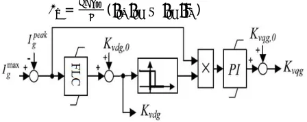
Fig. 6 presents a method for limiting the power pulsation references via adjusting Kvdg and Kvqg. In this method Kvdg
and Kvqgare initially set to pre-adjusted quantities Kvdg0 and Kvqg0. The unbalanced grid voltage is compensated using these fixed gains until the peak current of converter (Ipeakg) passes its maximum limit.
The suggested control scheme in Fig. 5 can be alternatively used for elimination of real and reactive power pulsations if
KrTeis set to zero.
IV. CURRENT/POWER LIMITING ALGORITHMS FOR THE GRID- AND ROTOR-SIDE CONVERTERS
Using power as a dynamic variable can cause over current of the power converter during transients and faults in a grid. This section presents an algorithm for limiting power references via sensing the converters currents.
A. Grid-Side Converter
In the control scheme for the grid-side converter (Fig. 4), the power capacity of the converter can be used for partially compensating the unbalanced stator voltage. However, it is necessary that the converter maintain the dc-link voltage via control of average real power and supplying the rotor real power has the highest priority. Thus, the maximum and mini-mum limits of average real power will be set to the maximini-mum and minimini-mum complex power as:
, =− , = = | | (25)
whereSmax g and Imax g are the maximum complex power and maximum current of GSC, respectively. Then, the limits for average reactive power should be calculated with respect to instantaneous real power as given by:
, =− , = ( ) − , (26)
The references for power pulsation components, Fig. 4, are:
∗, = , ∗, = (27)
Based on (27), Fig. 6 presents a method for limiting the power pulsation references via adjusting Kvdg and Kvqg. In this method Kvdg and Kvqgare initially set to pre-adjusted quantities Kvdg0 and Kvqg0. The unbalanced grid voltage is compensated using these fixed gains until the peak current of converter (Ipeakg) passes its maximum limit. Then, in the first step, Kvqgis decreased to reduce the q∗g,acand if q∗g,acreaches zero and still Ipeak g is beyond its limit, then
Kvdg is decreased to reduce p∗g,ac. Therefore, the unbalanced grid voltage compensation can be partially or completely deactivated during the over current of the grid-side converter.
B. Rotor-Side Converter
Under a normal operating condition, the reference for the stator real power is adjusted to capture the maximum wind energy. This reference can be obtained via any maximum power point tracking (MPPT) algorithm [24]. The stator reactive power reference is also adjusted to satisfy the power factor requirements at the grid. Therefore, the maximum currents of the rotor and stator windings determine the upper limits of the generator real and reactive powers. Similar to the grid-side converter, the limits for the generator real/reactives can be obtained as:
=− = = | | (28)
=− = ( ) − (29)
whereIsmax and Ssmax are the stator maximum current and complex power, respectively. Since the stator power is mainly
controlled via the rotor-side converter (RSC), the limits of the rotor complex power should be adjusted based on the stator complex power. The rotor complex power is
ISSN (Print) : 2320 – 3765 ISSN (Online): 2278 – 8875
I
nternational
J
ournal of
A
dvanced
R
esearch in
E
lectrical,
E
lectronics and
I
nstrumentation
E
ngineering
(A High Impact Factor, Monthly, Peer Reviewed Journal)
Website: www.ijareeie.com
Vol. 7, Issue 2, February 2018
Assuming that the stator and rotor resistances in a high-power generator are small quantities, the rotor voltage/current can be approximately expressed by:
= + (31)
=− − (32)
Substituting (31) and (32) in (30), we deduce:
= + = (− + ( +
( + + + | | (33)
Thus, the limits for the stator power components can be expressed as:
=− = = (34)
and the real/reactive power limits for the rotor-side converter can be defined as:
=max( , ) , = min( , ) (37)
=max( , ) , = min( , ) (38)
By using these limits during transients conditions, the capacity of RSC is partially used for injecting reactive power to the grid while the capacity of GSC is used for maintaining the dc-link voltage and compensation of unbalanced voltage.
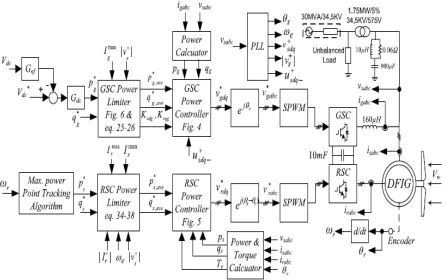
Fig. 7.Schematic diagram of the study system.
MATLAB/SIMULINK results are presented in this section for validating steady-state and dynamic performances of this proposed DFIG with integrated active filter capabilities
V. MATLAB RESULTS AND DISCUSSION
ISSN (Print) : 2320 – 3765 ISSN (Online): 2278 – 8875
I
nternational
J
ournal of
A
dvanced
R
esearch in
E
lectrical,
E
lectronics and
I
nstrumentation
E
ngineering
(A High Impact Factor, Monthly, Peer Reviewed Journal)
Website: www.ijareeie.com
Vol. 7, Issue 2, February 2018
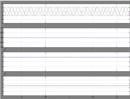
In this section, the working of this proposed GSC is presented as an active filter even when the wind turbine is in shutdown condition. The power that is coming into the PCC through GSC is considered as positive in this paper. The simulated performance of this proposed DFIG is presented at a 10.6-m/s wind speed as shown in Fig. 4. As the proposed DFIG is operating atMPPT, the reference speed of the DFIG is selected as 1750 rpm. The load currents are observed to be nonlinear in nature. The GSC is supplying required harmonics currents to the load for making grid currents (igabc) and stator currents (isabc) balanced and sinusoidal. Fig. 4 also shows the stator power (Ps), GSC power (Pgsc), load power (Pl), and grid power (Pg). At above synchronous speed, the power flow is from the GSC to PCC, so the GSC power is shown as positive. Total power produced by the DFIG is the sum of stator power (Ps) and GSC power (Pgsc). After feeding power to the load (Pl), the remaining power is fed to the grid (Pg). Fig. 5 (a)–(d) shows harmonic spectra and waveforms of grid current (iga), load current (ila), stator current (isa), and grid voltage (vga), respectively. From these harmonic spectra, one can understand that grid current and stator current THDs are less than 5% as per IEEE-519 standard [35] limits given inTable I. Fig. 5 shows test results by performing tests on the developed prototype at a fixed wind speed of 10.6 m/s. These test results are observed similar to the simulated results.
Fig 8.MATLAB SIMULINK Model of the Proposed DFIG
In this section, the working of this proposed GSC is presented as an active filter even when the wind turbine is in shutdown condition. The power that is coming into the PCC through GSC is considered as positive in this paper.
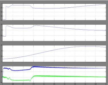
Fig. 9. The DFIG performance under unbalanced voltage using balanced controller: (a) stator real power; (b) stator reactive power; (c) torque; (d) stator and rotor currents.
ISSN (Print) : 2320 – 3765 ISSN (Online): 2278 – 8875
I
nternational
J
ournal of
A
dvanced
R
esearch in
E
lectrical,
E
lectronics and
I
nstrumentation
E
ngineering
(A High Impact Factor, Monthly, Peer Reviewed Journal)
Website: www.ijareeie.com
Vol. 7, Issue 2, February 2018
the stator power (Ps), GSC power (Pgsc), load power (Pl), and grid power (Pg). At above synchronous speed, the power flow is from the GSC to PCC, so the GSC power is shown as positive
As the proposed DFIG is operating atMPPT, the reference speed of the DFIG is selected as 1750 rpm. The load currents are observed to be nonlinear in nature. The GSC is supplying required harmonics currents to the load for making grid currents (igabc) and stator currents (isabc) balanced and sinusoidal.
Fig. 10. Simulated performance of the proposed DFIG-based WECS at fixed wind speed of 10.6 m/s (rotor speed of 1750 rpm).
ISSN (Print) : 2320 – 3765 ISSN (Online): 2278 – 8875
I
nternational
J
ournal of
A
dvanced
R
esearch in
E
lectrical,
E
lectronics and
I
nstrumentation
E
ngineering
(A High Impact Factor, Monthly, Peer Reviewed Journal)
Website: www.ijareeie.com
Vol. 7, Issue 2, February 2018
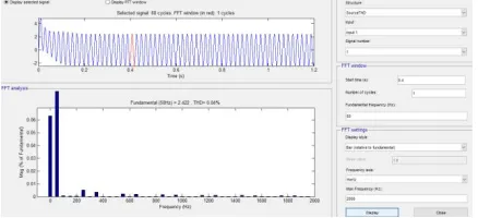
Fig 11Total Harmonic Distortion of Load current (Ilabc) in %
From these harmonic spectra, one can understand that grid current and stator current THDs are less than 5% as per IEEE-519 standard [35] limits given inTable I. Fig. 5 shows test results by performing tests on the developed prototype at a fixed wind speed of 10.6 m/s. These test results are observed similar to the simulated results.
Fig 12Total Harmonic Distortion of Source current (Isabc) in %
In this the total harmonic distortion will reduce to 12 percent at the load side From these harmonic spectra, one can understand that grid current and stator current THDs are less than 5% as per IEEE-519 standard [35] limits given inTable I. Fig. 5 shows test results by performing tests on the developed prototype at a fixed wind speed of 10.6 m/s. These test results are observed similar to the simulated results.
VI. CONCLUSION
ISSN (Print) : 2320 – 3765 ISSN (Online): 2278 – 8875
I
nternational
J
ournal of
A
dvanced
R
esearch in
E
lectrical,
E
lectronics and
I
nstrumentation
E
ngineering
(A High Impact Factor, Monthly, Peer Reviewed Journal)
Website: www.ijareeie.com
Vol. 7, Issue 2, February 2018
REFERENCES
1. M. Mohseni and S. M. Islam, “Review of international grid codes for wind power integration: Diversity, technology and a case for global standard,” Renew. Sustain. Energy Rev., vol. 16, no. 6, pp. 3876–3890, 2012.
2. C. Jauch, J. Matevosyan, T. Ackermann, and S. Bolik, “International comparison of requirements for connection of wind turbines to power systems,” Wind Energy, vol. 8, no. 3, pp. 295–306, 2005.
3. F. Shahnia, P. J. Wolfs, and A. Ghosh, “Voltage unbalance reduction in low voltage feeders by dynamic switching of residential cus-tomers among three phases,” IEEE Trans. Smart Grid, vol. 5, no. 3,pp. 1318–1327, May 2014.
4. R. Piwkoet al., “Integrating large wind farms into weak power grids with long transmission lines,” in Proc. CES/IEEE 5th Int. Power Electron.Motion Control Conf. (IPEMC), vol. 2. Dalian, China, 2006, pp. 1–7.
5. K. Lee, T. M. Jahns, W. E. Berkopec, and T. A. Lipo, “Closed-form analysis of adjustable-speed drive performance under input-voltage unbalance and sag conditions,” IEEE Trans. Ind. Appl., vol. 42, no. 3,pp. 733–741, May/Jun. 2006.
6. E. Nasr-Azadani, C. A. Cañizares, D. E. Olivares, and K. Bhattacharya, “Stability analysis of unbalanced distribution systems with synchronous machine and DFIG based distributed generators,” IEEE Trans. SmartGrid, vol. 5, no. 5, pp. 2326–2338, Sep. 2014.
7. H. Xu, J. Hu, and Y. He, “Integrated modeling and enhanced control of DFIG under unbalanced and distorted grid voltage conditions,”
IEEETrans. Energy Convers., vol. 27, no. 3, pp. 725–736, Sep. 2012.
8. [8] J. Hu and Y. He, “DFIG wind generation systems operating with limited converter rating considered under unbalanced network conditions—Analysis and control design,” Renew. Energy, vol. 36, no. 2,pp. 829–847, 2011.
9. Y. Yan, M. Wang, Z.-F. Song, and C.-L. Xia, “Proportional-resonant control of doubly-fed induction generator wind turbines for low-voltage ride-through enhancement,” Energies, vol. 5, no. 11, pp. 4758–4778, 2012.
10. C. Liu, F. Blaabjerg, W. Chen, and D. Xu, “Stator current harmonic control with resonant controller for doubly fed induction generator,” IEEE Trans. Power Electron., vol. 27, no. 7, pp. 3207–3220, Jul. 2012.
11. P. Zhou, Y. He, and D. Sun, “Improved direct power control of a DFIG-based wind turbine during network unbalance,” IEEE Trans.Power Electron., vol. 24, no. 11, pp. 2465–2474, Nov. 2009.
12. Y. Zhou, P. Bauer, J. A. Ferreira, and J. Pierik, “Operation of grid-connected DFIG under unbalanced grid voltage condition,” IEEE Trans.Energy Convers., vol. 24, no. 1, pp. 240–246, Mar. 2009.
13. L. Xu and Y. Wang, “Dynamic modeling and control of DFIG-based wind turbines under unbalanced network conditions,” IEEE Trans. PowerSyst., vol. 22, no. 1, pp. 314–323, Feb. 2007.
14. M. Savaghebi, A. Jalilian, J. C. Vasquez, and J. M. Guerrero, “Secondary control scheme for voltage unbalance compensation in an islanded droop-controlled microgrid,” IEEE Trans. Smart Grid, vol. 3, no. 2,pp. 797–806, Jun. 2012.
15. M. Hamzeh, H. Karimi, and H. Mokhtari, “Harmonic and negative-sequence current control in an islanded multi-bus MV microgrid,”
IEEETrans. Smart Grid, vol. 5, no. 1, pp. 167–176, Jan. 2014.
16. L. Xu, “Enhanced control and operation of DFIG-based wind farms during network unbalance,” IEEE Trans. Energy Convers., vol. 23, no. 4,pp. 1073–1081, Dec. 2008.
17. V.-T. Phan and H.-H. Lee, “Performance enhancement of stand-alone DFIG systems with control of rotor and load side converters using res-onant controllers,” IEEE Trans. Ind. Appl., vol. 48, no. 1, pp. 199–210, Jan./Feb. 2012.
18. G. Abad, M. A. Rodriguez, G. Iwanski, and J. Poza, “Direct power control of doubly-fed-induction-generator-based wind turbines under unbalanced grid voltage,” IEEE Trans. Power Electron., vol. 25, no. 2,pp. 442–452, Feb. 2010.
19. J. Alonso-Martinez, J. Eloy-Garcia, D. Santos-Martin, and S. Arnaltes, “A new variable-frequency optimal direct power control algorithm,”
IEEE Trans. Ind. Electron., vol. 60, no. 4, pp. 1442–1451, Apr. 2013.
20. H. Nian, Y. Song, P. Zhou, and Y. He, “Improved direct power control of a wind turbine driven doubly fed induction generator during transient grid voltage unbalance,” IEEE Trans. Energy Convers., vol. 26, no. 3,pp. 976–986, Sep. 2011.
21. E. Rezaei, A. Tabesh, and M. Ebrahimi, “Dynamic model and control of DFIG wind energy systems based on power transfer matrix,”
IEEETrans. Power Del., vol. 27, no. 3, pp. 1485–1493, Jul. 2012.
22. Tabesh and R. Iravani, “Multivariable dynamic model and robust control of a voltage-source converter for power system applications,” IEEE Trans. Power Del., vol. 24, no. 1, pp. 462–471, Jan. 2009.
23. D. Santos-Martin, J. L. Rodriguez-Amenedo, and S. Arnalte, “Direct power control applied to doubly fed induction generator under unbal-anced grid voltage conditions,” IEEE Trans. Power Electron., vol. 23, no. 5, pp. 2328–2336, Sep. 2008.
24. M. R. Patel, Wind and Solar Power Systems: Design, Analysis, andOperation. Boca Raton, FL, USA: CRC Press, 2006.