Compact Ring-LWE Cryptoprocessor
Sujoy Sinha Roy1, Frederik Vercauteren1, Nele Mentens1,
Donald Donglong Chen2 and Ingrid Verbauwhede1
1
ESAT/COSIC and iMinds, KU Leuven
Kasteelpark Arenberg 10, B-3001 Leuven-Heverlee, Belgium Email:{firstname.lastname}@esat.kuleuven.be
2
Department of Electronic Engineering, City University of Hong Kong Tat Chee Avenue, Kowloon, Hong Kong SAR
Email: [email protected]
Abstract. In this paper we propose an efficient and compact processor for a ring-LWE based encryption scheme. We present three optimizations for the Num-ber Theoretic Transform (NTT) used for polynomial multiplication: we avoid pre-processing in the negative wrapped convolution by merging it with the main algo-rithm, we reduce the fixed computation cost of the twiddle factors and propose an advanced memory access scheme. These optimization techniques reduce both the cycle and memory requirements. Finally, we also propose an optimization of the ring-LWE encryption system that reduces the number of NTT operations from five to four resulting in a 20% speed-up. We use these computational optimiza-tions along with several architectural optimizaoptimiza-tions to design an instruction-set ring-LWE cryptoprocessor. For dimension 256, our processor performs encryp-tion/decryption operations in 20/9 µs on a Virtex 6 FPGA and only requires 1349 LUTs, 860 FFs, 1 DSP-MULT and 2 BRAMs. Similarly for dimension 512, the processor takes 48/21 µs for performing encryption/decryption operations and only requires 1536 LUTs, 953 FFs, 1 DSP-MULT and 3 BRAMs. Our pro-cessors are therefore more than three times smaller than the current state of the art hardware implementations, whilst running somewhat faster.
Keywords. Lattice-based cryptography, ring-LWE, Polynomial multiplication, Number Theoretic Transform, Hardware implementation
1
Introduction
Lattice-based cryptography is considered a prime candidate for quantum-secure public key cryptography due to its wide applicability [27] and its security proofs that are based on worst-case hardness of well known lattice problems. Thelearning with errors (LWE) problem [26] and its ring variant known as ring-LWE [17] have been used as a solid foundation for several cryptographic schemes. The significant progress in the theory of lattice-based cryptography [19, 20, 25] has recently been followed by practical implementations [1, 7, 9, 22, 23, 28].
The ring-LWE based cryptosystems operate in a polynomial ringRq =Zq[x]/hf(x)i, where one typically choosesf(x) =xn+ 1 with na power of two, andq a prime with
q ≡ 1 mod 2n. An implementation thus requires the basic operations in such a ring
efficient polynomial multiplier architecture therefore is a pre-requisite for the deployment of ring-LWE based cryptography in real world systems.
The most important hardware implementations of polynomial multipliers for the ringsRq are [1, 9, 22, 23]. In [9], a fully parallel butterfly structure is used for the poly-nomial multiplier resulting in a huge area consumption. For instance, even for medium security, their ring-LWE cryptoprocessor does not fit on the largest FPGA of the Virtex 6 family. In [22], a sequential polynomial multiplier architecture is designed to use the FPGA resources in an efficient way. The multiplier uses a dedicated ROM to store all the twiddle factors which are required during the NTT computation. In [23] the authors integrated the polynomial multiplier [22] in a complete ring-LWE based encryption sys-tem and propose several syssys-tem level optimizations such as a better message encoding scheme and compression technique for the ciphertext. The work [1] tries to reduce the area of the polynomial multiplier by computing the twiddle factors whenever required, but as we will show, this could be improved substantially by re-arranging the loops in-side the NTT computation. Furthermore, the paper does not include an implementation of a complete ring-LWE cryptoprocessor.
Our contributions: In this paper we present a complete ring-LWE based encryption processor that uses the Number Theoretic Transform (NTT) algorithm for polynomial multiplication. The architecture is designed to have small area and memory requirement, but is also optimized to keep the number of cycles small. In particular, we make the following contributions:
1. During the NTT computation, the intermediate coefficients are multiplied by the twiddle factors that are computed using repeated multiplications. In [22] a pre-computed table (ROM) is used to avoid this fixed computation cost. The more compact implementation in [1] does not use ROM and computes the twiddle factors by performing repeated multiplications. In this paper we reduce the number of multiplications by re-arranging the nested loops in the NTT computation.
2. The implementations [1, 22] use negative wrapped convolution to reduce the number of evaluations in both the forward and backward NTT computations. However, the use of the negative wrapped convolution has a pre- and post-computation overhead. In this paper we basically avoid the pre-computation which reduces the cost of the forward NTT.
3. The intermediate coefficients are stored in memory (RAM) during the NTT compu-tation. Access to the RAM is a bottleneck for speeding-up the NTT compucompu-tation. In the implementations [1, 22], FPGA-RAM slices are placed in parallel to avoid this bottleneck. In this paper we propose an efficient memory access scheme which reduces the number of RAM accesses, optimizes the number of block RAMs and still achieves maximum utilization of the computational blocks.
4. The Knuth-Yao sampler [28] is slow due to the costly bit scanning operation. We reduce the cycle count using fast table lookup operations. We also optimize the area of the Knuth-Yao [28] sampler by reducing the width of the ROM. For the standard deviation 3.33 the area-optimized sampler consumes only 32 slices and is thus more compact and faster than the Bernoulli sampler in [24].
6. Finally, we optimize one of the most popular ring-LWE encryption schemes by re-ducing the number of NTT computations from five to four, thereby achieving a nearly 20% reduction in the computation cost.
The above optimizations result in a very compact architecture that is three times smaller than the current state of the art implementation [23] and even runs somewhat faster.
The remainder of the paper is organized as follows: In Section 2 we provide a brief mathematical background on ring-LWE and the NTT. Section 3 contains our opti-mization techniques of the NTT and Section 4 presents the actual architecture of our optimized NTT algorithm. A pipelined architecture is given in Section 5. In Section 6, we propose an optimization of an existing ring-LWE encryption scheme and propose an efficient architecture for the complete ring-LWE encryption system. Finally, Section 7 reports on the experimental results of this implementation.
2
Background
In this section we present a brief mathematical overview of the ring-LWE problem, the encryption scheme we will be optimizing and the NTT.
2.1 The LWE and ring-LWE Problem
Thelearning with errors(LWE) problem is a machine learning problem that is equivalent to worst-case lattice problems as shown by Regev [26] in 2005. Since then, the LWE problem has become popular as a basis for developing quantum secure lattice-based cryptosystems.
The LWE problem is parametrized by a dimension n≥1, an integer modulusq≥2 and an error distribution, typically a discrete Gaussian distributionXσover the integers with deviation σ and mean 0. The probability of sampling an integer z ∈ Z in the Gaussian distributionXσis given byρσ(z)/ρσ(Z) whereρσ(z) = exp
−z2
2σ2
andρσ(Z) =
P+∞
z=−∞ρσ(z). Note that some authors use the parameter s =
√
2πσ to define the Gaussian distribution or even denote the parametersbyσto add to the confusion.
For a uniformly chosens∈Znq, the LWE distributionAs,X overZnq ×Zq consists of tuples (a, t) wherea is chosen uniformly fromZnq andt=ha,si+e modq∈Zq ande is sampled from the error distributionX. Thesearch version of the LWE problem asks to findsgiven a polynomial number of pairs (a, t) sampled from the LWE distribution
As,X. In the decisionversion of the LWE problem, the solver needs to distinguish with
non-negligible advantage between a polynomial number of samples drawn from As,X
and the same number of samples drawn fromZnq×Zq. For hardness proofs of the search and decision LWE problems, interested readers are referred to [15].
The initial LWE encryption system in [26] is based on matrix operations which are quite inefficient and result in large key sizes. To achieve computational efficiency and to reduce the key size, an algebraic variant of the LWE calledring-LWE [17] uses special structured ideal lattices. Such lattices correspond to ideals in rings Z[x]/hfi, where f
with a ∈Rq chosen uniformly random and t =as+e∈ Rq, where s ∈Rq is a fixed secret element and ehas small coefficients sampled from the discrete Gaussian above. The resulting distribution onRq will also be denotedXσ.
The ring-LWE based encryption scheme that we will use was introduced in the full version of [17] and uses a global polynomiala ∈ Rq. Key generation, encryption and decryption are as follows:
1. KeyGen(a) : Choose two polynomialsr1, r2 ∈Rq from Xσ and compute p=r1− a·r2∈Rq. The public key is (a, p) and the private key isr2. The polynomialr1 is
simply noise and is no longer required after key generation.
2. Enc(a, p, m) : The message m is first encoded to ¯m ∈ Rq. Three polynomials
e1, e2, e3∈Rq are sampled fromXσ. The ciphertext then consists of two polynomials
c1=a·e1+e2 andc2=p·e1+e3+ ¯m∈Rq.
3. Dec(c1, c2, r2) : Computem′ =c1·r2+c2∈Rq and recover the original messagem from m′ using a decoder.
One of the simplest encoding functions maps a binary message m to the polynomial ¯
m∈Rqsuch that itsi-th coefficient is (q−1)/2 iff thei-th bit ofmis 1 and 0 otherwise. The corresponding decoding function then simply reduces the coefficients m′
i ofm
′
in the interval (−q/2, q/2] and decodes to 1 when|m′
i|> q/4 and 0 otherwise.
2.2 Parameter sets
To enable fair comparison with the state of the art [23], we have chosen to instantiate the cryptoprocessor for the same parameter sets (n, q, s) (recall s = √2πσ), namely
P1 = (256,7681,11.32) and P2 = (512,12289,12.18). Note that the choice of primes
is not optimal for fast modular reduction. To estimate the security level offered by these two parameter sets we follow the security analysis in [16] and [14] which improves upon [15, 29]. Apart from the dimensionn, the hardness of the ring-LWE problem mainly depends on the ratio q/σ, where clearly the problem becomes easier for larger ratios. Although neither parameter set was analyzed in [16], parameter setP1is similar to the
set (256,4093,8.35) from [16] which requires 2105 seconds to break, or still over 2128
elementary operations. For paramater setP2 we expect it to offer a high security level
consistent with AES-256 (following [9]).
We limit the Gaussian sampler in our implementation to 12σto obtain a negligible statistical distance (<2−90) from the true discrete Gaussian distribution. Although one
can normally sample the secretr2∈Rq also from the distributionXσ, we restrictr2 to
have binary coefficients.
2.3 The Number Theoretic Transform
Algorithm 1:Iterative NTT
Input: Polynomiala(x)∈Zq[x] of degreen−1 andn-th primitive rootωn∈Zqof unity
Output: PolynomialA(x)∈Zq[x] = NTT(a)
begin 1
A←BitReverse(a);
2
form= 2tonbym= 2mdo 3
ωm←ωn/mn ;
4
ω←1 ;
5
forj= 0tom/2−1do 6
fork= 0ton−1bymdo 7
t←ω·A[k+j+m/2] ;
8
u←A[k+j] ;
9
A[k+j]←u+t;
10
A[k+j+m/2]←u−t;
11
end 12
ω←ω·ωm;
13
end 14
end 15
end 16
The FFT and NTT: Recall that the n-point FFT (with n = 2k) is an efficient method to evaluate a polynomial a(x) =Pn−1
j=0 ajxj ∈Z[x] in the n-th roots of unity
ωi
n fori= 0, . . . , n−1 whereωn denotes a primitiven-th root of unity. More precisely, on input the coefficients [a0, . . . , an−1] and ωn, the FFT computes F F T([aj], ωn) = [a(ω0
n), a(ω1n), . . . , a(ωnn−1)] inθ(nlogn) time. Due to the orthogonality relations between then-th roots of unity, we can compute the inverse FFT simply as 1
nF F T(·, ω
−1
n ). The NTT replaces the complex roots of unity by roots of unity in a finite ring Zq. Since we require elements of ordern,qis chosen to be a prime withq≡1 mod 2n. Note furthermore that the NTT immediately leads to a fast multiplication algorithm in the ringSq =Zq[x]/(xn−1): indeed, given two polynomialsa, b∈Sq we can easily compute their (reduced) productc=a·b∈Sq by computing
c=N T Tω−1n N T Tωn(a)∗N T Tωn(b)
, (1)
where∗ denotes point-wise multiplication.
The NTT computation is usually described as recursive, but in practice we use an in-place iterative version taken from [4] that is given in Algorithm 1. For the inverse NTT, an additional scaling of the resulting coefficients byn−1is performed. The factors ω used in line 8 are called thetwiddle factors.
Multiplication in Rq: Recall that we will use Rq =Zq[x]/hfiwith f =xn+ 1 and n= 2k. Sincef(x)|x2n−1 we could use the 2n-point NTT to compute the multiplication inRq at the expense of three 2n-point NTT computations and a reduction by trivially embedding the ring Rq into Sq, i.e. expanding the coefficient vector of a polynomial
a∈Rq by addingnextra zero coefficients. However, we can do much better by exploiting the special relation between the roots ofxn+ 1 andx2n−1 using a technique known as thenegative wrapped convolution.
n-point NTT (instead of a 2n-point NTT) on the scaled polynomialsa′(x) =a(ω 2n·x) and b′(x) = a(ω
2n·x). The point-wise multiplication gives the evaluations of c(x) =
a(x)b(x) modf(x) in the roots off, and the classical inversen-point NTT thus results in the coefficients of the scaled polynomialc′(x) =c(ω
2n·x). To recover the coefficients
ci of c(x), we therefore simply have to compute ci = c′i ·ω
−i
2n. Note that the scaling operation byn−1 can be combined with the multiplications ofc′
i byω
−i
2n.
3
Optimization of the NTT Computation
In this section we optimize the NTT and compare with the recent hardware implemen-tations of polynomial multipliers [1, 22, 23]. First, the fixed cost involved in computing the powers ofωnis reduced, then the pre-computation overhead in the forward negative-wrapped convolution is optimized, and finally an efficient memory access scheme is pro-posed that reduces the number of memory accesses during the NTT and also minimizes the number of block RAMs in the hardware architecture.
3.1 Optimizing the Fixed Computation Cost
In line 13 of Algorithm 1 the computation of the twiddle factorω←ω·ωmis performed in the j-loop. This computation can be considered as a fixed cost. However in [1, 22] the j-loop and the k-loop are interchanged, such that ω is updated in the innermost loop which is much more frequent than in Algorithm 1. To avoid the computation of the twiddle factors, in [22] all the twiddle factors are kept in a pre-computed look-up table (ROM) and are accessed whenever required. As the twiddle factors are not computed on-the-fly, the order of the two innermost loops does not result in an additional cost. However in [1] a more compact polynomial multiplier architecture is designed without using any look-up table and the twiddle factors are simply computed on-the-fly during the NTT computation. Hence in [1], the interchanged loops cause substantial additional computational overhead. In this paper our target is to design a very compact polynomial multiplier. Hence we do not use any look-up table for the twiddle factors and follow Algorithm 1 to avoid the extra computation of [1].
3.2 Optimizing the Forward NTT Computation Cost
Here we revisit the forward negative-wrapped convolution technique used in [1, 22, 23]. Recall that the negative-wrapped convolution corresponds to a classicaln-point NTT on the scaled polynomialsa′
(x) =a(ω2n·x) andb′(x) = (ω2n·x). Instead of first pre-computing these scaled polynomials and then performing a classical NTT, it suffices to note that we can integrate the scaling and the NTT computation. Indeed, it suffices to change the initialization of the twiddle factors in line 5 of Algorithm 1: instead of initializingωto 1, we can simply setω=ω2m. The rest of the algorithm remains exactly the same, and no pre-computation is necessary. Note that this optimization only applies to the NTT itself and not to the inverse NTT.
3.3 Optimizing the Memory Access Scheme
A[k+j] andA[k+j+m/2] are first read from memory and then arithmetic operations (one multiplication, one addition and one subtraction) are performed. The newA[k+j] andA[k+j+m/2] are then written back to memory. During one iteration of the inner-most loop, the arithmetic circuits are thus used only once, while the memory is read or written twice. This leads to idle cycles in the arithmetic circuits. The polynomial multi-plier in [22] uses two parallel memory blocks to provide a continuous flow of coefficients to the arithmetic circuits. However this approach could result in under-utilization of the RAM blocks if the coefficient size is much smaller than the word size (for example in the ring-LWE cryptosystem [17]). In the literature there are many papers on efficient memory management schemes using segmentation and efficient address generation (see [18]) for the classical FFT algorithm. Another well known approach is the constant geometry FFT (or NTT) which always maintains a constant index difference between the processed coefficients [21]. However the constant geometry algorithm is not in-place and hence not suitable for resource constrained platforms. In [1] memory usage is im-proved by keeping two coefficientsA[k] andB[k] of the two input polynomialsAandB
in the same memory location. We propose a memory access scheme which is designed to minimize the number of block RAM slices and to achieve maximum utilization of computational circuits present in the NTT architecture.
Since the two coefficients A[k+j] and A[k+j +m/2] are processed together in Algorithm 1, we keep the two coefficients as a pair in one memory location.
Let us analyze two consecutive iterations of the m-loop (line 3 in Algorithm 1) for
m=m1andm=m2wherem2= 2m1. In them1-loop, for somej1andk1(maintaining
the loop bounds in Algorithm 1) the coefficients (A[k1+j1], A[k1+j1+m1/2]) are
processed as a pair. Thenk increments tok1+m1 and the processed coefficient pair is
(A[k1+m1+j1], A[k1+m1+j1+m1/2]). Now from Algorithm 1 we see that the coefficient A[k1+j1] will again be processed in the m2-loop with coefficient A[k1+j1+m2/2].
Sincem2= 2m1, the coefficientA[k1+j1+m2/2] is the coefficientA[k1+j1+m1] which
is updated in them1-loop for k=k1+m1. Hence during the m1-loop if we swap the
updated coefficients fork=k1 andk=k1+m1 and store (A[k1+j1], A[k1+j1+m1])
and (A[k1+j1+m1/2], A[k1+j1+ 3m1/2]) as the coefficient pairs in memory, then the
coefficients in a pair have a difference ofm2/2 in their index and thus are ready for the m2-loop. The operations during the two consecutive iterationsk=k1 andk=k1+m1
duringm=m1are shown in Algorithm 2 in lines 8-15. During the operationsu1,t1,u2
andt2 are used as temporary storage registers.
A complete description of the efficient memory access scheme is given in Algorithm 2. In this algorithm for all values of m < n, two coefficient pairs are processed in the innermost loop and a swap of the updated coefficients is performed before writing back to memory. For m =n, no swap operation is required as this is the final iteration of the m-loop. The coefficient pairs generated by Algorithm 2 can be re-arranged easily for another (say inverse) NTT operation by performing address-wise bit-reverse-swap operation. Appendix A describes the memory access scheme using an example.
4
The NTT Processor Organization
Algorithm 2:Iterative NTT : Memory Efficient Version
Input: Polynomiala(x)∈Zq[x] of degreen−1 andn-th primitive rootωn∈Zqof unity
Output: PolynomialA(x)∈Zq[x] = NTT(a)
begin 1
A←BitReverse(a); /* Coefficients are stored in the memory as proper pairs */
2
form= 2ton/2bym= 2mdo 3
ωm←m-th primitiveroot(1) ;
4
ω←squareroot(ωm) or 1 /* Depending on forward or backward NTT */ ;
5
forj= 0tom/2−1do 6
fork= 0ton/2−1bymdo 7
(t1, u1)←(A[k+j+m/2], A[k+j]) /* From MEMORY[k+j] */ ;
8
(t2, u2)←(A[k+m+j+m/2], A[k+m+j]) /* MEMORY[k+j+m/2] */ ;
9
t1←ω·t1;
10
t2←ω·t2;
11
(A[k+j+m/2], A[k+j])←(u1−t1, u1+t1) ;
12
(A[k+m+j+m/2], A[k+m+j])←(u2−t2, u2+t2) ;
13
MEMORY[k+j]←(A[k+j+m], A[k+j]) ;
14
MEMORY[k+j+m/2]←(A[k+j+ 3m/2], A[k+j+m/2]) ;
15
end 16
ω←ω·ωn;
17
end 18
end 19
m←n;
20
k←0 ;
21
ω←squareroot(ωm) or 1 /* Depending on forward or backward NTT */ ;
22
forj= 0tom/2−1do 23
(t1, u1)←(A[j+m/2], A[j]) /* From MEMORY[j] */ ;
24
t1←ω·t1;
25
(A[j+m/2], A[j])←(u1−t1, u1+t1) ;
26
MEMORY[j]←(A[j+m/2], A[j]) ;
27
ω←ω·ωm;
28
end 29
end 30
H1H2H3
L2 L1 H1 L1 L1 H1 L2 H3 H2 L1 ωm ω2n n−1 R R R R R 2 1 3 4 5 1 HL 0 HL HL1 L1 2 2 MULdata ROMdata Multiplier DOUT DIN Control Signals read address write enable write address NTT−ALU Control−Address Unit RAM Load2 Input Coefficients Output Coefficients DIN_high DOUT_high DOUT_low DIN_low Load1 Small ROM ω 1 HL
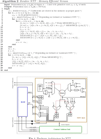
The Memory Block is implemented as a simple dual port RAM. To accommodate two coefficients, the word size is 2⌈logq⌉where q is the prime modulus. In FPGAs, a RAM can be implemented as a distributed or as a block RAM. When the amount of data is large, block RAM is the ideal choice.
The Arithmetic Unit (NTT-ALU) is designed to support Algorithm 2 along with other operations such as polynomial addition, point-wise multiplication and rearrange-ment of the coefficients. This NTT-ALU is interfaced with the memory block and the control-address unit. The central part of the NTT-ALU consists of a modular multiplier and addition/subtraction circuits.
Now we describe how the different components of the NTT-ALU are used during the butterfly steps (excluding the last loop form=n). First, the memory location (k+j) is fetched and then the fetched data (t1, u1) is stored in the input register pair (H1, L1).
The same also happens for the memory location (k+j+m/2) in the next cycle. The multiplier computes ω·H1 and the result is added to or subtracted fromL1 using the
adder and subtracter circuits to compute (u1+ωt1) and (u1−ωt1) respectively. In the
next cycle the register pair (R1, R4) is updated with (u1−ωt1, u1+ωt1). Another clock
transition shifts the contents of (R1, R4) to (R2, R5). In this cycle the pair (R1, R4) is
updated with (u2−ωt2, u2+ωt2) as the computation involving (u2, t2) from the location
(k+j+m/2) lags by one cycle. Now the memory location (k+j) is updated with the register pair (R4, R5) containing (u2 +ωt2, u1+ωt1). Finally, in the next cycle the
memory location (k+j+m/2) is updated with (u2−ωt2, u1−ωt1) using the register
pair (R2, R3). The execution of the last m-loop is similar to the intermediate loops,
without any data swap between the output registers. The register pair (R2, R5) is used
for updating the memory locations. In Figure 1, the additional registers (H2, H3 and L2) and multiplexers are used for supporting operations such as addition, point-wise
multiplication and rearrangement of polynomials. The Small-ROM block contains the fixed valuesωm,ω2n, their inverses andn−1. This ROM has depth of order log(n).
The Control-and-Address Unit consists of three counters form, j and k in Algo-rithm 2 and comparators to check the terminal conditions during the execution of any loop. The read address is computed fromm,j andkand then delayed using registers to generate the write address. The control-and-address unit also generates the write enable signal for the RAM and the control signals for the NTT-ALU.
5
Pipelining the NTT Processor
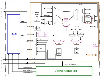
The maximum frequency of the NTT-ALU is determined by the critical path (red dashed line in Figure 1) that passes through the modular multiplier and the adder (or sub-tracter) circuits . To increase the operating frequency of the processor, we implement efficient pipelines based on the following two observations.
Assume that the modular multiplier has dm pipeline stages and that the output is latched in a buffer. In the (dm+ 1)th cycle after the initialisation ofω·t1, the buffer is
updated with the resultω·t1. Now we need to compute u1+ω·t1andu1−ω·t1 using
the adder and subtracter circuits. Hence we delay the data u1 by dm cycles so that it appears as an input to the adder and subtracter circuits in the (dm+ 1)th cycle. This delay operation is performed with the help of a shift registerL1, . . . , Ldm+1 as shown in
Figure 2.
Observation 2:Every increment ofj in Algorithm 2 requires a newω (line 17). If the multiplier has dm pipeline stages, then the register-ω in Figure 1 is updated with the new value ofω in the (dm+ 2)th cycle. Since this new ω is used by the next butterfly operations, the data dependency results in an interruption in the chain of butterfly operations for dm+ 1 cycles. In any m-loop, the total number of such interruption cycles is (m/2−1)·(dm+ 1).
To reduce the number of interruption cycles, we use a small look-up table to store a few twiddle factors. Let the look-up table (red dashed rectangle in Figure 2) have
l registers containing the twiddle factors (ω, . . . ωωl−1
m ). This look-up table is used to provide the twiddle factors during the butterfly operations for sayj =j′
to j =j′
+
l−1. The next timej increments, new twiddle factors are required for the butterfly operations. We multiply the look-up table withωl
mto compute the nextltwiddle factors (ωωl
m, . . . ωωm2l−1). The multiplications are independent of each other and hence can be processed in a pipeline. The butterfly operations are resumed after ωωl
m is loaded in the look-up table. Thus using a small-look-up table of sizel we reduce the number of interruption cycles to (m
2l−1)·(dm+ 1). In our architecture we usel= 4; a larger value ofl will reduce the number of interruption cycles, but will cost additional registers.
H1 L1 L2 H3 H2 L1 L 2 L 1 H 1 H 2 H 3 ... m 1
d +
L
ωωl−1 m
m d +1
L HL2
m d +1
L
m d +1
L ωm ω2n n−1 R R R R R 4 5 MULdata DOUT DIN DIN_high DIN_low Control Signals read address write enable write address NTT−ALU Control−Address Unit RAM HL1 0 HL2 Multiplier ... .. . Pipeline Register Input Coefficients Output Coefficients Load1 Load2 ω 1 HL 1 2 3 Small ROM 1 H 1 ROMdata DOUT_high DOUT_low
Optimal Pipeline Strategy for Speed : During the execution of any m-loop in Algorithm 2, the number of butterfly operations is n/2. In the pipelined NTT-ALU, the cycle requirement for the n/2 butterfly operations is slightly larger than n/2 due to an initial overhead. The state machine jumps to theω calculation state m
2l−1 times resulting in (m
2l−1)·(dm+ 1) interruption cycles. Hence the total number of cycles spent in executing anym-loop can be approximated as shown below:
Cyclesm≈n 2 + (
m
2l −1)·(dm+ 1)
Let us assume that the delay of the critical path with no pipeline stages isDcomb. When the critical path is split in balanced-delay stages using pipelines, the resulting delay (Ds) can be approximated as Dcomb
(dm+da), wheredmandda are the number of pipeline stages in
the modular multiplier and the modular adder (subtracter) respectively. Since the delay of the modular adder is small compared to the modular multiplier, we have da ≪dm. Now the computation time for them-loop is approximated as
Tm≈ Dcomb (dm+da)
n
2 + (
m
2l −1)·(dm+ 1)
≈Dsn
2 +Cm.
HereCmis constant (assumingda≪dm) for a fixed value ofm. From the above equa-tion we find that the minimum computaequa-tion time can be achieved whenDsis minimum. Hence we pipeline the datapath to achieve minimumDs. The DSP based coefficient mul-tiplier is optimally pipelined using the Xilinx IPCore tool, while the modular reduction block is suitably pipelined by placing registers between the cascaded adder and sub-tracter circuits.
6
The ring-LWE Encryption Scheme
The ring-LWE encryption scheme in [23] optimizes computation cost by keeping the fixed polynomials in the NTT domain. The message encryption and decryption operations require three and two NTT computations respectively. In this paper we reduce the number of NTT operations for decryption from two to one. The proposed ring-LWE encryption scheme is described below:
1. KeyGen(a) : Choose a polynomial r1 ∈ Rq from Xσ, choose another polynomial
r2 with binary coefficients and then compute p = r1 −a·r2 ∈ Rq. The NTT is performed on the three polynomialsa,pandr2 to generate ˜a, ˜pand ˜r2. The public
key is (˜a,p˜) and the private key is ˜r2.
2. Enc(˜a,p, m˜ ): The messagemis first encoded to ¯m∈Rq. Three polynomialse1, e2, e3∈ Rq are sampled from Xσ. The ciphertext is then computed as:
˜
e1←N T T(e1); e˜2←N T T(e2)
( ˜c1,c˜2)← ˜a∗e˜1+ ˜e2; ˜p∗e˜1+N T T(e3+ ¯m)
3. Dec( ˜c1,c˜2,r˜2) : Compute m′ as m′ = IN T T( ˜c1∗r˜2+ ˜c2) ∈ Rq and recover the original messagemfromm′
using a decoder.
. . .
Sampler Gaussian Discrete RNG
M0 M5
Control−Address Unit
Memory File
NTT−ALU
Sampler
Load2 Load1
Encoder
Message Bit Input Coefficients
Input Buffers
Decoder
Two Message Bits
Output Coefficients
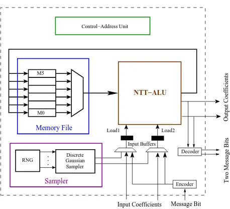
Fig. 3.Ring-LWE Cryptoprocessor
6.1 Hardware Architecture for the Ring-LWE Encryption Scheme
Figure 3 shows a hardware architecture for the ring-LWE encryption system. The basic building blocks used in the architecture are: the memory file, the arithmetic unit, the discrete Gaussian sampler and the control-address generation unit. The arithmetic unit is the NTT-ALU that we described in the previous section. Here we briefly describe the memory file and the discrete Gaussian sampler.
The Memory File is designed to support the maximum memory requirement that occurs during the encryption of the message. Six memory blocksM0toM5are available
in the memory file and are used to store ¯a, ¯p,e1,e2,e3and ¯mrespectively. The memory
blocks have width 2⌈logq⌉bits and depthn/2. All six memory blocks share a common read and a write address and have a common data-input line, while their data-outputs are selected through a multiplexer. Any of the memory blocks in the memory file can be chosen for read and write operation. Due to the common addressing of the memory blocks, the memory file supports one read and one write operation in every cycle. The Discrete Gaussian Sampler is based on the compact Knuth-Yao sampler [13] architecture proposed in [28] and have sufficiently large precision and tail-bound to satisfy a maximum statistical distance of 2−90 to a true discrete Gaussian distribution
random walk [28] is started with the initial distance obtained from the second lookup operation.
The Cycle Count for the encryption and decryption operations can be minimized in the following way. During the encryption operation, first the three error polynomialse1, e2 ande3 are generated by invoking the discrete Gaussian sampler 3ntimes. Next the
encoded message ¯mis added toe3and then three consecutive forward NTT operations
are performed one1,e2and (e3+ ¯m). Finally the ciphertext ˜c1, ˜c2is obtained using two
coefficient-wise multiplications followed by two polynomial additions and two rearrange-ment operations. The decryption operation requires one coefficient-wise multiplication, one polynomial addition and finally one inverse NTT operation.
During the encryption operation, 3n samples are generated to construct the three error polynomials. Our fast Knuth-Yao sampler architecture requires 805 and 1644 cycles for the dimensions 256 and 512 respectively on average to generate the three error polynomials. The polynomial addition and point-wise multiplication operations require
n cycles each with a small overhead. The consecutive processing of I forward NTTs share a fixed computation costf cf wd and require in total f cf wd+I×n2log(n) cycles. SimilarlyIconsecutive inverse NTTs are processed inf cinv+I×n2log(n) +I×ncycles. One interesting point is that the fixed costf cinv is larger thanf cf wd as it includes the computation ofωi
2n/N (Section 2.3) fori= (0. . . n−1). This observation has been used to optimize the overall ring-LWE based encryption scheme in Section 6. The additional
I×n cycles during the inverse NTTs are required to multiply the coefficients by the scaling factors. The rearrangement of polynomial coefficients after an NTT operation requires less thanncycles. From the above cycle counts for each primitive operations, we see that the encryption and decryption operations require totalf cf wd+32nlog(n) + 10n andf cinv+n2log(n) + 3ncycles respectively along with additional overhead. Our ring-LWE architecture has the fixed computation costsf cf wd= 667 andf cinv = 1048 cycles forn= 256; andf cf wd= 1139 andf cinv = 1959 cycles forn= 512.
7
Experimental Results
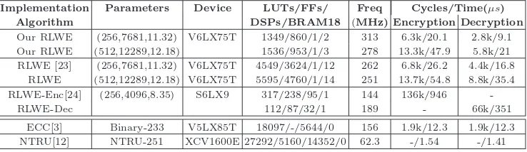
We have implemented the proposed ring-LWE cryptosystem on the Xilinx Virtex 6 FPGA for the parameter sets (n, q, s) : (256,7681,11.32) and (512,12289,12.18). The area and performance results are obtained from the Xilinx ISE12.2 tool after place and route analysis and are shown in Table 1. In the table we also compare our results with other reported hardware implementations of the ring-LWE encryption scheme.
Our implementations are both fast and small thanks to the proposed computational optimizations and resource efficient design style. The cycle counts shown in the table do not include the cycles for data loading or reading operations. Our Knuth-Yao samplers have less than 2−90 statistical distances from the corresponding true discrete Gaussian
distributions and consume around 164 LUTs and have delay less than 2.5ns(with opti-mization goal for speed). Such a small delay makes the sampler suitable for integration in the pipelined ring-LWE processor under a single clock domain. We use nine parallel true random bit generators [8, 6] to generate the random bits for the sampler. The set of true random bit generators consumes 378 LUTs and 9 FFs.
Implementation Parameters Device LUTs/FFs/ Freq Cycles/Time(µs)
Algorithm DSPs/BRAM18 (MHz) Encryption Decryption
Our RLWE (256,7681,11.32) V6LX75T 1349/860/1/2 313 6.3k/20.1 2.8k/9.1 Our RLWE (512,12289,12.18) 1536/953/1/3 278 13.3k/47.9 5.8k/21 RLWE [23] (256,7681,11.32) V6LX75T 4549/3624/1/12 262 6.8k/26.2 4.4k/16.8
RLWE (512,12289,12.18) V6LX75T 5595/4760/1/14 251 13.7k/54.8 8.8k/35.4 RLWE-Enc[24] (256,4096,8.35) S6LX9 317/238/95/1 144 136k/946
-RLWE-Dec 112/87/32/1 189 - 66k/351
ECC[3] Binary-233 V5LX85T 18097/-/5644/0 156 1.9k/12.3 1.9k/12.3 NTRU[12] NTRU-251 XCV1600E 27292/5160/14352/0 62.3 -/1.54 -/1.41
Table 1.Performance and Comparison
the largest FPGA of the Virtex 6 family. Performance results such as cycle count and frequency are not reported in their paper. The architecture uses a Gaussian distributed array for sampling of the error coefficients up to a tail-bound of±2s.
The implementation in [23] is small and fast due to its resource-efficient design style. A high operating frequency is achieved using pipelines in the architecture. The architecture uses a ROM that keeps all the twiddle factors required during the NTT operation. This approach reduces the fixed computation cost (f c) but consumes block RAM slices in FPGAs. Additionally, the parallel RAM blocks in the NTT processor result in a larger memory requirement compared to our design. The discrete Gaussian sampler is based on the inversion sampling method [5] and has a maximum statistical distance of 2−22 to a true discrete Gaussian distribution. Since the inversion sampling
requires many random bits to output a sample value, an AES core is used as a pseudo-random number generator. The AES core itself consumes an additional 803 LUTs and 341 FFs compared to our true random number generator. Another reason behind the larger area consumption of [23] compared to our architecture is due to the fact that the architecture supports different parameter sets at synthesis time. Our ring-LWE processor is also designed to achieve scalability for various parameter sets. In our architecture the control block remains the same; while only the data-width and the modular reduction block changes for different parameter sets. Hence our architecture is also configurable by generating the HDL codes for various parameter sets using a C program.
A very recent paper [24] proposes ring-LWE encryption and decryption architectures targeting small area at the cost of performance. The implementation uses a quadratic-complexity multiplier instead of a complicated NTT based polynomial multiplier. Addi-tionally the special modulus also saves some amount of area as the modular reduction is free of cost. However if we consider a similar quadratic-complexity multiplication based architecture in the dimension n = 512, then the cycle requirement will be nearly 40 times compared to our NTT-based ring-LWE processor. Our target was to use FPGA resources more efficiently without affecting the performance and to achieve similar speed as [23]. The paper [24] also designs a compact Bernoulli sampler that consumes 37 slices for the standard deviation 3.33 and is thus smaller in area compared to the Knuth-Yao sampler in [28]. The Bernoulli sampler requires on average 96 random bits and 144 cy-cles to output a sample. In the contrast the Knuth-Yao sampler [28] requires on average 5 random bits and 17 cycles per sample and is thus faster than the Bernoulli sampler. In this paper we have reduced the area consumption of the Knuth-Yao sampler [28] by reducing the width of the ROM and the scan-register from 32 bits to 12 bits and by simplifying the control unit. These area optimizations do not affect the cycle require-ment of the sampler, but result in an area of only 32 slices for the overall sampler. The area optimized Knuth-Yao sampler is both smaller and faster compared to the Bernoulli sampler in [24].
We also compare our results with other cryptosystems such as ECC and NTRU. The ECC processor [3] over the NIST recommended binary fieldGF(2233) requires 12.3µsto
compute one scalar multiplication and is faster than our ring-LWE processor. However the ECC processor is designed to achieve high speed and hence consumes very large area compared to our ring-LWE processor. The NTRU scheme [12] is much faster than our ring-LWE processor due to its less complicated arithmetic. However the parameters chosen for the implementation in [12] have security around 64 bits [11]. Though secure parameter sets for the NTRU based encryption have been proposed in [10], no hardware implementation for the secure parameter sets is available in the literature.
8
Conclusion
Acknowledgment
This work was supported by the Research Council KU Leuven: TENSE (GOA/11/007), by iMinds, by the European Union Seventh Framework Programme (FP7/2007-2013) under grant agreement n. 609611 (PRACTICE), by the Flemish Government, FWO G.0550.12N, by the Hercules Foundation AKUL/11/19. The first author is supported by the Erasmus Mundus PhD Scholarship. We are thankful to Bohan Yang and Vladimir Rozic for useful technical discussions related to memory utilisation and random number generation.
References
1. A. Aysu, C. Patterson, and P. Schaumont. Low-cost and Area-efficient FPGA Implemen-tations of Lattice-based Cryptography. InHOST, pages 81–86. IEEE, 2013.
2. D. Bernstein. Fast Multiplication and its Applications. Algorithmic Number Theory, 44:325–384, 2008.
3. C. Rebeiro, S. Sinha Roy, and D. Mukhopadhyay. Pushing the Limits of High-Speed
GF(2m
) Elliptic Curve Scalar Multiplication on FPGAs. InCryptographic Hardware and Embedded Systems, volume 7428 of Lecture Notes in Computer Science, pages 494–511. Springer Berlin Heidelberg, 2012.
4. T. Cormen, C. Leiserson, and R. Rivest. Introduction To Algorithms. http://staff.ustc.edu.cn/∼csli/graduate/algorithms/book6/toc.htm.
5. L. Devroye. Non-Uniform Random Variate Generation. Springer-Verlag, New York, 1986. 6. M. Dichtl and J. D. Golic. High-Speed True Random Number Generation with Logic Gates Only. InCryptographic Hardware and Embedded Systems - CHES 2007, volume 4727 of
LNCS, pages 45–62. Springer Berlin, 2007.
7. T. Frederiksen. A Practical Implementation of Regev’s LWE-based Cryptosystem. In
http://daimi.au.dk/ jot2re/lwe/resources/, 2010.
8. J. D. Golic. New Methods for Digital Generation and Postprocessing of Random Data.
IEEE Transactions on Computers, 55(10):1217–1229, 2006.
9. N. G¨ottert, T. Feller, M. Schneider, J. Buchmann, and S. Huss. On the Design of Hardware Building Blocks for Modern Lattice-Based Encryption Schemes. InCryptographic Hardware and Embedded Systems CHES 2012, volume 7428 ofLNCS, pages 512–529. Springer Berlin, 2012.
10. P. Hirschhorn, J. Hoffstein, N. Howgrave-graham, and W. Whyte. Choosing NTRUEncrypt parameters in light of combined lattice reduction and MITM approaches. InIn Proc. ACNS 2009, LNCS 5536, pages 437–455. Springer-Verlag, 2009.
11. N. Howgrave Graham. A Hybrid Lattice-Reduction and Meet-in-the-Middle Attack Against NTRU. In Advances in Cryptology - CRYPTO 2007, volume 4622 of Lecture Notes in Computer Science, pages 150–169. Springer Berlin Heidelberg, 2007.
12. A. Kamal and A. Youssef. An FPGA implementation of the NTRUEncrypt cryptosystem. InMicroelectronics (ICM), 2009 International Conference on, pages 209–212, Dec 2009. 13. D. E. Knuth and A. C. Yao. The Complexity of Non-Uniform Random Number Generation.
Algorithms and Complexity, pages 357–428, 1976.
14. T. Lepoint and M. Naehrig. A Comparison of the Homomorphic Encryption Schemes FV and YASHE. IACR Cryptology ePrint Archive, 2014:62, 2014.
15. R. Lindner and C. Peikert. Better Key Sizes (and Attacks) for LWE-based Encryption.
CT-RSA 2011, pages 319–339, 2011.
17. V. Lyubashevsky, C. Peikert, and O. Regev. On Ideal Lattices and Learning with Errors over Rings. InAdvances in Cryptology EUROCRYPT 2010, volume 6110 ofLecture Notes in Computer Science, pages 1–23. Springer Berlin Heidelberg, 2010.
18. Y. Ma and L. Wanhammar. A Hardware Efficient Control of Memory Addressing for High-performance FFT Processors. Signal Processing, IEEE Transactions on, 48(3):917– 921, Mar 2000.
19. D. Micciancio. Lattices in Cryptography and Cryptanalysis. 2002.
20. P. Q. Nguyen and J. Stern. The Two Faces of Lattices in Cryptology. InCryptography and Lattices, International Conference (CaLC 2001), volume 2146 of LNCS, pages 146–180. Springer-Verlag, Berlin, 2001.
21. J. Pollard. The Fast Fourier Transform in a Finite Field. Mathematics of Computation, 25:365374, 1971.
22. T. P¨oppelmann and T. G¨uneysu. Towards Efficient Arithmetic for Lattice-Based Cryp-tography on Reconfigurable Hardware. In A. Hevia and G. Neven, editors, Progress in Cryptology LATINCRYPT 2012, volume 7533 ofLNCS, pages 139–158. Springer Berlin, 2012.
23. T. P¨oppelmann and T. G¨uneysu. Towards Practical Lattice-Based Public-Key Encryption on Reconfigurable Hardware. InSelected Areas in Cryptography – SAC 2013, Lecture Notes in Computer Science, pages 68–85. Springer Berlin Heidelberg, 2014.
24. T. P¨oppelmann and T. G¨uneysu. Area Optimization of Lightweight Lattice-Based En-cryption on Reconfigurable Hardware. InProc. of the IEEE International Symposium on Circuits and Systems (ISCAS-14), 2014, Preprint.
25. O. Regev. Quantum Computation and Lattice Problems.SIAM J. Comput., 33(3):738–760, Mar. 2004.
26. O. Regev. On Lattices, Learning with Errors, Random Linear Codes, and Cryptography. In
Proceedings of the thirty-seventh annual ACM symposium on Theory of computing, STOC ’05, pages 84–93, New York, NY, USA, 2005. ACM.
27. O. Regev. Lattice-Based Cryptography. In C. Dwork, editor, Advances in Cryptology -CRYPTO 2006, volume 4117 ofLNCS, pages 131–141. Springer Berlin, 2006.
28. S. Sinha Roy, F. Vercauteren, and I. Verbauwhede. High Precision Discrete Gaussian Sampling on FPGAs. In Selected Areas in Cryptography – SAC 2013, Lecture Notes in Computer Science, pages 383–401. Springer Berlin Heidelberg, 2014.
29. J. van de Pol and N. P. Smart. Estimating key sizes for high dimensional lattice-based systems. In M. Stam, editor,IMA Int. Conf., volume 8308 ofLecture Notes in Computer Science, pages 290–303. Springer, 2013.
Appendix A
Table 2 shows the memory contents during the execution of Algorithm 2 for n = 16. The column-heading represents (m, j, k) during the iterations. The end loop in line 19 of Algorithm 2 form= 16 performs no swap and is shown in the table using⋆symbol.
Appendix B
Address Initial (2,0,0) (2,0,6) (4,0,0) (4,0,4) (4,1,4) (8,3,0) (16,7,0)⋆
0 A1A0 A2 A0 A2 A0 A4 A0 A4A0 A4 A0 A8 A0 A8 A0 1 A3A2 A3 A1 A3 A1 A5 A1 A9 A1 A9 A1 2 A5A4 A6 A4 A6 A2 A6A2 A6 A2 A10 A2 A10A2 3 A7A6 A7 A5 A7 A3 A11 A3 A11A3 4 A9A8 A10A8 A12A8 A12A8 A12 A4 A12A4 5 A11A10 A11A9 A13A9 A13 A5 A13A5 6 A13A12 A14A12 A14A10A14A10 A14 A6 A14A6 7 A15A14 A15A13 A15A11 A15 A7 A15A7
Table 2.Memory content during the steps in a 16-point NTT
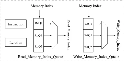
Instruction
Iteration
Memory Index Memory Index
Read_Memory_Index_Queue Write_Memory_Index_Queue
Read_Memory_Index Write_Memory_Index
RdQ0
RdQ1
RdQ2
WtQ0
WtQ1
WtQ2
Fig. 4.Instruction Execution Hardware
1. LOAD : A memory block indexed byW tQ0 is loaded withncoefficients. Since two coefficients are processed in a cycle, the instruction takes n/2 +ǫcycles.
2. ENCODE-LOAD : A memory block indexed by W tQ0 is loaded with an encoded message. The input message bits are first encoded using the encoder and then loaded in the memory block as proper coefficient-pairs. This instruction requiresn+ǫcycles. 3. GAUSSIAN-LOAD : A memory block indexed byW tQ0 is loaded with nsamples.
The cycle count for this operation depends on the standard deviation andn. 4. FNTT/INTT : Is used to perform inplace forward or inverse NTT. The number of
consecutive NTTs is stored in the iteration-register and the indexes of the memory blocks are kept in the read-memory-index-queue
5. ADD/CMULT : Two memory blocks indexed by RdQ0 and RdQ1 are added or coefficient-wise multiplied. The result is stored in the memory block indexed by
W tQ0. These two instructions requiren+ǫcycles.
6. REARRANGE : Performs rearrangement of coefficient pairs in a memory block indexed byRdQ0. This instruction requires less thanncycles.