FINITE-ELEMENT GEOMETRIC STIFFNESS MATRIX LUMPING BY
NUMERICAL INTEGRATION FOR STABILITY ANALYSIS
S.J. Shah
Framatome ANP Inc. 1724 Mt. Athos Road Lynchburg, VA 24505, USA sshah @ framatech.com
Abstract
Using numerical integration in the formulation of the finite-element geometric stiffness matrix and placing movable nodes at integration points causes the geometric stiffness matrix to become lumped or diagonal. The consistent geometric stiffness matrix which is a non-diagonal matrix, is normally used in the finite-element eigenvalue buckling problem. Altering the method to deliver a diagonal (lumped) geometric stiffness matrix simplifies the process of solving the eigenvalue problem and results in computational savings. The advantage of the diagonal geometric stiffness matrix, also called the lumped force stiffness matrix, is that it usually provides lower buckling loads than the magnitude of the true buckling load. As an example of the method, the lumped force stiffness matrix formulation using the numerical integration is presented for the beam, shell, and rectangular plate elements.
Introduction
The stiffness, geometric stiffness, and mass matrices for an element are normally derived in the finite-element analysis by substituting the assumed displacement field into the principle of virtual work. Numerical integration is technically convenient and used routinely as a device in the finite-element method. It is also used to lump the mass matrix without losing accuracy. Usually, nodal-quadrature rules or the Gauss-rules are employed in the construction of the lumped mass matrixes. This paper shows that the numerical integration technique and displacement interpolation functions used in the formulation of the lumped-mass matrix can also be easily adapted to the formulation of the lumped-force stiffness matrix. Techniques used to derive the lumped mass matrix are discussed by Hughes [ 1] and Fried and Malkus [2] for quadratic rod elements and the four-node cubic element, respectively.
The mass matrix originates from the integration of the displacement shape functions squared, while the lumped force stiffness matrix originates from the derivative of the shape functions squared. This difference requires a modification to the displacement interpolation functions used in the formulation of the lumped force stiffness matrix, which causes the modified
function
Nmi
and its derivativeNim,
to vanish on all nodes, except node i. Although not presented in thisshape paper,
expanded displacement interpolation functions that can generate lumped force stiffness matrices can easily apply to elements such as the isoparametric 5-node quadrilateral element and 3-node bar element.
One method used to construct the lumped-force stiffness matrices employs the trapezoidal numerical integration scheme, which places the element nodes at integration points. This scheme locates the integration points at the element end points. Placing the element nodes at the integration points results in a diagonal element for in-plane direct forces, with the lumped forces being the integration weights. Because the nodes are located at the end points, the trapezoidal rule does not require the modification of the displacement interpolation functions to produce a lumped force stiffness matrix. Examining the beam, shell, and rectangular plate elements illustrates the approach.
In-Plane Force Lumping by Trapezoidal Rule
A method for diagonalizing the lumped geometric stiffness matrix using the trapezoidal rule is presented. The trapezoidal rule places the element nodes at integration points. The effect of such a rule on the geometric stiffness matrix is to diagonalize it. To illustrate the approach, lumped force stiffness matrices are derived in this section for the beam, shell, and rectangular plate elements.
Several numerical examples of the buckling of the flat plates using the lumped force stiffness matrix are presented and compared with "exact" solutions in this paper. Calculations of elastic critical loads using the lumped force stiffness matrix approach for several other structures such as frames, curved beams, circular plates, and shells of revolution may be of interest to the reader. These numerical examples are presented by Shah and Pilkey [3].
SMiRT 16, Washington DC, August 2001 Paper # 2057
Beam Element
The geometric stiffness matrix is defined as
where P is the axial force.
e
]- I
o
(1)
N~ = Ni, x, [N] = [N I, N 2, N 3, N 4] (2)
Matrix [N] is called the displacement shape function matrix. Here it is 1 by 4 and contains the entries
3X 2 2X 3
N 1 - 1 - g2 + ~ g3
2 x 2 x 3 N 2 - x - ~ + g ---5-
g
N 3 =
3X 2 2X 3
,~2 ,~3
2 3
X X
g
(3)
The term g is the length of a beam element and the term x is the distance from the left end of a horizontal beam. The shape functions given by Equation (3) are used in the formulation of both the static stiffness matrix and the consistent geometric stiffness matrix.
Equations (2) and (3) provide
6 x 6X 2 Nl,x - - g-"T + ~ g 3
4 x 3X 2
N 2
- 1 - ~
g----g-
6x
6x z
N 3 x , -g2
g3
2 x 3X 2 N 4 x = , g ~ g3
At x = 0 or at x = g, these Ni,x given by Equation (4) contain a single one and three zeros as given below
(4)
N , , o = 0 Ni,e = 0
N2,0 = 1 N2,e = 0
N3,0 = 0 N3,e=O
N4,0 = 0 N4,e = 1 (5)
With the trapezoidal rule, the one-dimensional integral formula is
X2
I f ( x ) d x = f ( x l ) +
f ( x 2 )2
XI
(X2 -- X 1 ) (6)
The preceding six steps (Equations (1) through (6)) yield a lumped force stiffness matrix:
-0 0 0 0 P g
0 0 0
2
0 0 0 0 P g 0 0 0
2
(7)
Note that half of the lumped force is lumped at each rotational (i.e., slope) degree of freedom and that there are zero lumped forces at the translational degrees of freedom. Because the nodes are located at the end points, the trapezoidal rule will produce a lumped force stiffness matrix. This element lumped force stiffness matrix is the same as that given by Shah and Pilkey [3 ].
S h e l l E l e m e n t
In the shell element, the expression for the rotations ~s and 130 given by Brush and Almroth [4] are
dw
- ( 8 )
ds
dw
B 0 ~ - - ~
(r)dO
where
r = s sin cz
= distance of a point on middle surface from axis of symmetry, w = normal displacement,
J]s = rotation of meridian,
[3o = component of rotation with respect to circumferential coordinate,
s = a distance from a boundary of a shell structure,
cz = angle between meridian and axis (semi angle at vortex of cone).
The derivatives of w can be related to the nodal parameters { v } from the displacement functions given by Zienkiewicz [5] as
dw
Z
dw
rdO
- [ N ' ] { v } (9)
In the shell element, the geometric stiffness matrix is obtained from Zienkiewicz [5] as
I,,l
(10)where the radius r must be expressed as a function of ~ as shown below before the above integration is carried out. For the element with two nodes, i and j,
Nso = meridional stress components at any point through the shell thickness prior to buckling,
N0o = tangential stress components at any point through the shell thickness prior to buckling.
The integration of Equation (10) using the trapezoidal rule provides 'the same lumped force stiffness matrix as given by Shah and Pilkey [3].
Rectangular Plate Element
Rectangular plate elements yield to the same approach used for beam elements. Consistent geometric stiffness matrices are explicitly stated by Kapur and Hartz [6] and Przemieniecki [7]. A lumped force stiffness matrix for a rectangular element with bending deformation is derived in this section, and the results are utilized to determine buckling stress coefficients of flat rectangular plates with various boundary conditions. The results show the advantage of the lumped force stiffness matrix method, which usually provides lower buckling loads than the exact value.
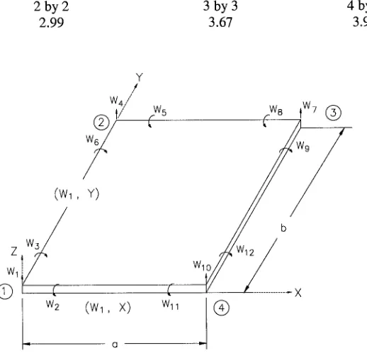
Finite-element buckling analyses of rectangular plates are performed by means of rectangular plate elements having 12 degrees-of-freedom shown in Figure 1. A simple derivation using the principle of virtual work leads to the formula for the geometric stiffness matrix.
]- If [N'Y IN'I,
< ay
where t is the element thickness. Membrane stresses presumed known a priori in the buckling problem are
b]-I 7y
where
And
u
Px, Py = membrane applied loads/unit area in x-direction, and y-direction, respectively, prior to buckling, positive for tension;
m
Pxy = applied shear load/unit area prior to buckling.
Matrix [N] relates plate slopes w,x and w,y to element nodal displacements { v }:
_
{vl, x,
w, y
(11)
where w is the lateral displacement and commas denote partial differentiation with respect to the following subscript.
The lateral displacement w for a plate element shown in Figure 1 can be represented in the form given by Przemieniecki [7]
w = [N]{v}
where
I N ] -
1 - ~'r/- (3 - 2 ( ) ( 2 (1- r/) - (1 - ()(3
- 2/'])/'] 2( 1 - ( ) r / ( 1 -
17) 2b
- ( ( 1 -
~')2 (1-/7)
a
( 1 - ( 1 ( 3 - 2r/)r/2 + ~'(1- ( ) ( 1 - 2()r/
- ( 1 - ()(1 - r/)r/2b
- ((1 - ( ) 2 r/a
( 3 - 2 ( ) ( 2 r / - (r/(1- r/l(1- 2r/)
- ( ( 1 - r/)r/2 b
(1 - ~')~'2/7 a
( 3 - 2 ( ) ( 2 ( 1 - r/) + (r/(1- r/)(1 - 2r/)
(r/(1 - r/) 2 b
( 1 - ( ) ( z ( 1 - r/)a
( _ x
and r / - y
a
b
a = the element length of the plate in the x-direction, b = the element width of the plate in the y-direction.
Using Equations (11) and (12)
[N,] r -
- r/+ ( 1 - r / ) ( - 6 ( + 6 ( 2 ) + r/2 (3 - 2r/)
r/(1- r/Z)b(1- 2 ( )
(-1 + 4 ( - 3 ( 2 ) ( 1 - r/)a
- (3 - 2r/lr/2 + (1 - 6 ( + 6 ( 2 )r/
(1-/7)/72b
(-1 + 4 ( - 3(2)r/a
( 6 ( - 6 ( 2 ) r 1 - r/(1- r/)
- (1- r/)r/2b
( 2 ( - 3(2)r/a
( 6 ( - 6 ( 21(1- r/) + r/(1- r/l(1- 2r/)
/7(1-/72)b
( 2 ( - 3 ( 2 ) ( 1 - rl)a
- ( + ( 3 - 2 ( ) ( 2 - ( 1 - ( ) ( 6 r / - 6 r / 2 )
(1- ( ) ( 1 - 4r/+ 3r/Z)b
+ ( ( 1 - ( ) 2 a
(1- ( ) ( 6 r / - 6r/2 ) + ( ( 1 - ( ) ( 1 - 2 ( )
- (1- ( ) ( 2 r / - 3r/Z)b
- ( ( 1 - ( 2 ) a
( 3 - 2 ( ) ( 2 - ( ( 1 - 6r/+ +6r/2 )
- ( ( 2 r / - 3r/2 )b
( 1 - ( ) ( 2 a
_ ( 2
(3 - 2 ( ) + ( ( 1 - 6r/+
6/'] 2 )( ( 1 - 4r/+ 3r/2)b
- ( 1 - ( ) ( 2 a
With the trapezoidal rule, for the two-dimensional function, the integration formula is
(12)
1 1 1 1
f f F((,T])d(d~ ~ f f F 1 ((,T])F 2 ((,~)d(d~
oo
oo
1 1
= ~ F 1 (0,0) F 2 (0,0) --I- ~ F 1
(1,0)F 2 (1,0)
1 1
+--/71 (0,1)F 2
(0,1)
+ F 1 (1,1)F 2(1,1)
4
4
(14)
If the plate is compressed uniformly in the x-direction and the y-direction only, then the trapezoidal rule will produce a lumped force stiffness matrix (from Equations (13) and (14)). Equation (15) shows it in the matrix form.
+
-0 0
0 0
0 0
0 0
0 0
0 0
0 0
0 0
0 0
0 0
0 0
0 0
m
P y t a b
4
]_
Pxtb
4
Some Typical Examples
0 0 0 0 0 0 0 0 0 0-
0 0 0 0 0 0 0 0 0 0
1
0 0 0 0 0 0 0 0 0
0 0 0 0 0 0 0 0 0 0
0 0 0 0 0 0 0 0 0 0
0 0 0
10 0 0 0 0 0
0 0 0 0 0 0 0 0 0 0
0 0 0 0 0 0 0 0 0 0
0 0 0 0 0 0
1 0 0 0
0 0 0 0 0 0 0 0 0 0
0 0 0 0 0 0 0 0 0 0
0 0 0 0 0 0 0 0 0
1-0 0 0 0 0 0 0 0 0 0
0
1 0 0 0 0 0 0 0 0
0 0 0 0 0 0 0 0 0 0
0 0 0 0 0 0 0 0 0 0
0 0 0 0
10 0 0 0 0
0 0 0 0 0 0 0 0 0 0
0 0 0 0 0 0 0 0 0 0
0 0 0 0 0 0 0
1 0 0
0 0 0 0 0 0 0 0 0 0
0 0 0 0 0 0 0 0 0 0
0 0 0 0 0 0 0 0 0 0
0 0 0 0 0 0 0 0 0 0
0 0-
0 0
0 0
0 0
0 0
0 0
0 0
0 0
0 0
0 0
1 0
0 0
(15)
In all three cases, the plate is compressed in the x-direction only. For a comparison, the results of the exact solution given by Timoshenko [8] are shown. In each case, k is the buckling stress coefficient in the equation
Pcr
- k (1 _ v2--- ~ (16)where
E = Young's modulus, v = Poisson's ratio, and t = plate thickness.
in which
Ly
is the total width of the plate in the y-direction. A fixed square plate uniformly compressed in both directions is also analyzed. Table 4 summarizes the results of this case.In all cases, three sizes of the element are used, representing the division of one quadrant of the plate into 4, 9, and 16 square elements. The 4-, 9-, and 16-element solutions converge rapidly to the exact values, and the buckling stress coefficient is always lower than the exact value.
Conclusions and Discussion
A method for lumping the finite-element consistent geometric stiffness matrix using numerical integration is presented. It is shown that the numerical integration technique and displacement interpolation functions used in the formulation of the lumped-mass matrix can be easily adopted in the formulation of the lumped-force stiffness matrix. To illustrate this method, the lumped force stiffness matrix formulation using the numerical integration is presented for the beam, shell and rectangular plate elements.
Demonstrative examples for the buckling analysis of the flat plates are given to show the application of the lumped force stiffness matrix approach for the stability problems. The lumped force stiffness matrix tends to provide lower buckling loads rather than the exact value if sufficient discretization of the structure for the lumped parameter is provided. It is shown that the solutions converge rapidly to the exact value as the number of elements increase in representation of the plate structure.
References
[1] Hughes, T. J. R., Hilber, H. M., and Taylor R. L., "A Reduction Scheme for Problems of Structural Dynamics," International Journal of Solids and Structures, Vol. 12, pp. 749-767, 1976.
[2] Fried, I., and Malkus, D. J., "Finite Element Mass Lumping by Numerical Integration Without Convergence Rate Loss," International Journal of Solids and Structures, Vol. 11, pp. 249-249, 1975.
[3]
[4]
Shah, S. J. and Pilkey, W. C., "Lumped Parameter Approach to Stability Analysis," ASCE Journal of Engineering Mechanics, Vol. 119, pp. 2109-2129, 1993.
Brush, D.O., and Almroth, B. O., Buckling of Bars, Plates and Shells, McGraw Hill Book Company, 1975 Edition.
[5]
[6]
[7]
Zienkiewcz, O. C., The Finite Element Method, McGraw Hill Book Company, Third Edition, New York, 1979.
Kapur, K. K. and Hartz, B. J., "Stability of Plates Using the Finite Element Method," JEM Div., Vol. 92, No. EM2, pp. 177-195, 1966.
Przemieniecki, J. S., "Discrete-Element Methods for Stability Analysis," Aero J, Vol. 72, No. 12, pp. 1077-1086, 1968.
Table 1 Values of Factor k for a Simply Supported Square Plate Under Uniform Compression in One Direction
Exact Value of k = 3.29
Grid Size 2 by 2 3 by 3 4 by 4
k 2.56 3.18 3.21
Table 2 Values of Factor k for a Square Plate Fixed at All Sides Under Uniform Compression in One Direction
Exact Value of k = 7.7
Grid Size 2 by 2 3 by 3 4 by 4
K 4.5 6.26 7.1
Table 3 Values of k for a Square Plate Simply Supported at Edges b and Fixed at Edges a
Exact Value of k = 6.32
Grid Size 2 by 2 3 by 3 4 by 4
K 4.32 5.62 6.20
Table 4 Values of k for a Fixed Plate under Uniform Compression in Two Directions. Known Value of k = 4.4
Grid Size 2 by 2 3 by 3 4 by 4
K 2.99 3.67 3.95
Y ,¢ / w4/
(Wl,
x(')/
©
(
I_ W2
(Wl, X)
w8
qw 7(~
Ja
(
,
. . . .Note: Typical nodal d.o.f, in term of partial derivatives shown at Node 1.