Available online:
https://edupediapublications.org/journals/index.php/IJR/
P a g e | 2059Predictive Controller based Active Power Filter for Power
Quality Control
P. Vin ay ku mar[ 1 ], B. Srin u[ 2 ]
[1]Assistant Professor, Department of Electrical Engineering, REC, Nalgonda, T.S, INDIA [2]Assistant Professor, Department of Electrical Engineering, SRTIST, Nalgonda, T.S, INDIA
A b s tract: The primary contribution of this paper is a predictive control algorithm designed and implemented specifically for this application. Traditionally, active power filters have been controlled using pre-tuned controllers, such as PI-type or adaptive, for the current as well asfor the dc-voltage loops. PI controllers must be designed based on the equivalent linear model, while predictive controllers use the nonlinear model, which is closer to real operating conditions. A detailed yet simple mathematical model of the active power filter, including the effect of the equivalent power system impedance, is derived andused to design the predictive control algorithm. The compensation performance of the proposed active power filter and the associated control scheme under steady state and transient operating conditions is demonstrated through simulation results.
Key wo rd s : Shunt active filter, harmonics, active power, power quality.
I. INTRODUCTION
The non-uniform nature of power generation directly affects voltage regulation and creates voltage distortion in power systems. This new scenario in power distribution systems will require more sophisticated compensation techniques. Although active power filters implemented with three-phase four-leg voltage-source inverters (4L-VSI) have already been presented in the technical literature, the primary contribution of this paper is a predictive control algorithm designed and implemented specifically for this application. Traditionally, active power filters have been controlled using pre-tuned controllers, such as PI-type or adaptive, for the current as well asfor the dc-voltage loops. PI controllers must be designed based on the equivalent linear model, while predictive controllers use the nonlinear model, which is closer to real operating conditions. An accurate model obtained using predictive controllers improves the performance of the active power filter, especially during transient operating conditions, because it canquickly follow the current-reference signal while maintaining a constant dc-voltage. So far, implementations of predictive control in power converters have been used mainly in induction motor drives. In the case of motor drive applications, predictive control represents a very intuitive control scheme that handles multivariable characteristics, simplifies the treatment
ofdead-time compensations, and permits pulse-width modulator replacement. However, these kinds of applications present disadvantages related to oscillations and instability created from unknown load parameters. One advantage of the proposed algorithm is that it fits well in active power filter applications, since the power converter output parameters are well known. These output parameters are obtained from the converter output ripple filter and the power system equivalent impedance. The converter output ripple filter is part of the active power filter design and the power system impedance is obtained from well-known standard procedures. In the case of unwell-known system impedance parameters, an estimation methodcan be used to derive an accurate R–L equivalent impedance model of the system. This paper presents the mathematical model of the 4L-VSI and the principles of operation of the proposed predictive control scheme, including the design procedure. The complete description of the selected current reference generator implemented in the active power filter is also presented. Finally, the proposed active power filter and the effectiveness of the associated control scheme compensation are demonstrated through simulation results.
II. CONVERTER DESCRIPTION
Available online:
https://edupediapublications.org/journals/index.php/IJR/
P a g e | 2060Fig ure 1: Three-phase equivalent circuit of the proposed sh u n t activ e p o wer filter
This circuit considers the power system equivalent impedance Zs, the converter output ripple filter impedance Zf, and the load
impedance ZL. The four-leg PWM converter topology is shown
in Fig. 2. This converter topology is similar to the conventional three-phase converter with the fourth leg connected to the neutral bus of the system. The fourth leg increases switching states from 8 (23) to 16 (24), improving control flexibility and
output voltage quality, and is suitable for current unbalanced compensation.
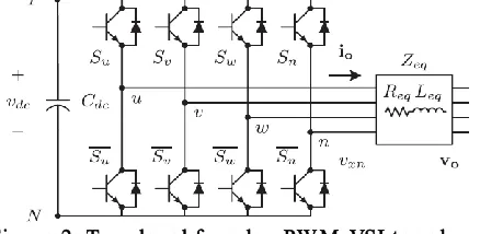
Fig u re 2: Two -lev el fo u r-leg PW M -VSI to p o lo g y
Where Req and Leq are the 4L-VSI output parameters expressed as Thevenin impedances at the converter output terminals Zeq. Therefore, the Thevenin equivalent impedance is determined by a series connection of the ripple filter impedance Zf and a parallel arrangement between the system equivalent impedance Zs and the load impedance ZL.
For this model, it is assumed that ZL>Zs, that the resistive part of the system’s equivalent impedance is neglected, and that the series reactance is in the range of 3–7% p.u., which is an acceptable approximation of the real system. Finally, Req = Rf and Leq = Ls+ Lf.
III. CONTROL STRA TEGY
Dig ital p red ictiv e cu rren t co n tro l
The block diagram of the proposed digital predictive current control scheme is shown in Fig. 3. This control scheme is basically an optimization algorithm and, therefore, it has to be implemented in a microprocessor. Consequently, the analysis has to be developed using discrete mathematics in order to consider additional restrictions such as time delays and approximations. The main characteristic of predictive control is the use of the system model to predict the future behavior of the variables to be controlled. The controller uses this information to select the optimum switching state that will be applied to the power converter, according to predefined optimization criteria. The predictive control algorithm is easy to implement and to understand, and it can be implemented with three main blocks, as shown in Fig. 3
Fig ure 3: Proposed predictive d ig ital cu rren t co n tro l b lo ck d iag ram
Cu rren t Referen ce Gen erato r
This unit is designed to generate the required current reference that is used to compensate the undesirable load current components. In this case, the system voltages, the load currents, and the dc-voltage converter are measured, while the neutral output current and neutral load current are generated directly from these signals.
Prediction Model
The converter model is used to predict the output converter current. Since the controller operates in discrete time, both the controller and the system model must be represented in a discrete time domain. The discrete time model consists of a recursive matrix equation that represents this prediction system. This means that for a given sampling time Ts, knowing the converter switching states and control variables at instant kTs , it is possible to predict the next states at any instant [k + 1]Ts .Due to the first-order nature of the state equations that describe the model, a sufficiently accurate first-order approximation of the derivative is considered in this paper.
In order to predict the output current io at the instant (k + 1), the input voltage value Vo and the converter output voltage VxN, are required. The algorithm calculates all 16 values
associated with the possible combinations that the state variables can achieve.
Co s t Fu n ctio n Op timizatio n
In order to select the optimal switching state that must be applied to the power converter, the 16 predicted values obtained for io[k + 1] are compared with the reference using a cost function g, as follows:
g[k + 1] = (i∗ou[k + 1]− iou[k + 1])2+ (i∗ov[k + 1]− iov[k +
1])2+ (i∗ow[k + 1] − iow[k + 1])2+ (i∗on[k + 1] − ion [k +1])2.
The output current (io) is equal to the reference (i∗o) when g = 0. Therefore, the optimization goal of the cost function is to achieve a g value close to zero. The voltage vector vxN that minimizes the cost function is chosen and then applied at the next sampling state. During each sampling state, the switching state that generates the minimum value of g is selected from the 16 possible function values. The algorithm selects the switching state that produces this minimal value and applies it to the converter during the k + 1 state.
Cu rren t referen ce g en eratio n
Available online:
https://edupediapublications.org/journals/index.php/IJR/
P a g e | 2061This characteristic avoids voltage fluctuations that deteriorate the current reference signal affecting compensation performance. The current reference signals are obtained from the corresponding load currents as shown in Fig. 4. This module calculates the reference signal currents required by the converter to compensate reactive power, current harmonic and current imbalance.
Where the value of THD(L) includes the maximum compensable
harmonic current, defined as double the sampling frequency fs. The frequency of the maximum current harmonic component that can be compensated is equal to one half of the converter switching frequency.
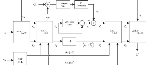
Fig ure 4: dq-based current reference generator block d iag ram. Where the value of THD(L) includes the maximum compensable
harmonic current, defined as double the sampling frequency fs. The frequency of the maximum current harmonic component that can be compensated is equal to one half of the converter switching frequency.
The dq-based scheme operates in a rotating reference frame; therefore, the measured currents must be multiplied by the sin(wt) and cos(wt) signals. By using dq-transformation, the d current component is synchronized with the corresponding phase-to-neutral system voltage, and the q current component is phase-shifted by 90◦. The sin(wt) and cos(wt) synchronized reference signals are obtained from a synchronous reference frame (SRF) PLL. The SRF-PLL generates a pure sinusoidal waveform even when the system voltage is severely distorted. Tracking errors are eliminated, since SRF-PLLs are designed to avoid phase voltage unbalancing, harmonics (i.e., less than 5% and 3% in fifth and seventh, respectively), and offset caused by the nonlinear load conditions and measurement errors.
Allow-pass filter (LFP) extracts the dc component of the phase currents id to generate the harmonic reference components −id. The reactive reference components of the phase-currents are obtained by phase-shifting the corresponding ac and dc components of iq by 180◦. In order to keep the dc-voltage constant, the amplitude of the converter reference current must be modified by adding an active power reference signal ie with the d-component, as will be explained in Section IV-A. The resulting signals i∗d and i∗q are transformed back to a three-phase system by applying the inverse Park and Clark
transformation. The cutoff frequency of the LPF used in this paper is 20 Hz.
The current that flows through the neutral of the load is compensated by injecting the same instantaneous value obtained from the phase-currents, phase-shifted by 180◦, as shown next
i∗on= −(iLu+ iLv+ iLw)
One of the major advantages of the dq-based current reference generator scheme is that it allows the implementation of a linear controller in the dc-voltage control loop. However, one important disadvantage of the dq-based current reference frame algorithm used to generate the current reference is that a second order harmonic component is generated in id and iq under unbalanced operating conditions. The amplitude of this harmonic depends on the percent of unbalanced load current (expressed as the relationship between the negative sequence current iL,2 and the positive sequence current iL,1 ). The second-order harmonic cannot be removed from id and iq, and therefore generates a third harmonic in the reference current when it is converted back to abc frame. Since the load current does not have a third harmonic, the one generated by the active power filter flows to the power system.
DC-Vo ltag e Co n tro l
The dc-voltage converter is controlled with a traditional PI controller. This is an important issue in the evaluation, since the cost function is designed using only current references, in order to avoid the use of weighting factors. Generally, these weighting factors are obtained experimentally, and they are not well defined when different operating conditions are required. Additionally, the slow dynamic response of the voltage across the electrolytic capacitor does not affect the current transient response. For this reason, the PI controller represents a simple and effective alternative for the dc-voltage control.
The dc-voltage remains constant (with a minimum value of √6Vs(rms) ) until the active power absorbed by the converter decreases to a level where it is unable to compensate for its losses. The active power absorbed by the converter is controlled by adjusting the amplitude of the active power reference signal ie , which is in phase with each phase voltage. In the block diagram shown in Fig. 5, the dc-voltage vdc is measured and then compared with a constant reference value v∗dc. The error (e) is processed by a PI controller, with two gains, Kp and Ti. Both gains are calculated according to the dynamic response requirement. Fig. 5 shows that the output of the PI controller is fed to the dc-voltage transfer function Gs, which is represented by first-order system.
Available online:
https://edupediapublications.org/journals/index.php/IJR/
P a g e | 2062IV. SIM ULA TION RESULTS
A simulation model for the three-phase four-leg PWM converterwith the parameters shown in Table I has been developedusingMATLAB-Simulink. The objective is to verify the currentharmonic compensation effectiveness of the proposed control scheme under different operating conditions. A six-pulse rectifier was used as a nonlinear load.
The active filter startsto compensate at t = t1. At this time, the active power filter injects an output current iou to compensate current harmonic components, current unbalanced, and neutral current simultaneously.
During compensation, the system currents is show sinusoidalwaveform, with low total harmonic distortion (THD = 3.93%).At t = t2, a three-phase balanced load step change is generatedfrom 0.6 to 1.0 p.u. The compensated system currents remain sinusoidal despite the change in the load current magnitude. Finally, at t = t3, a single-phase load step change is introduced inphase u from 1.0 to 1.3 p.u., which is equivalent to an 11% currentimbalance. As expected on the load side, a neutral currentflows through the neutral conductor (iLn), but on the source side,no neutral current is observed (isn ). Simulated results show thatthe proposed control scheme effectively eliminates unbalancedcurrents. Additionally, Fig. 8 shows that the dc-voltage remainsstable throughout the whole active power
filter operation.
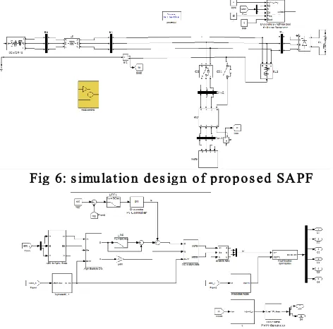
Fig 6: s imu latio n d es ig n o f p ro p o s ed SA PF
Fig 7: p red ictiv e d ig ital cu rren t co n tro l circu it
Fig ure 8: Simulated Waveforms of the Phase to Neutral Source Vo ltag e, Lo ad Cu rren t , Sy s tem Neu tral Cu rren t
Fig ure 9: Load current, system neutral current, system cu rren t
Fig u re 10: DC Vo ltag e
V. CONCLUSION
The use of a predictive control algorithm forthe converter current loop proved to be an effective solutionfor active power filter applications, improving current tracking capability, and transient response. Improved dynamic current harmonics and a reactive powercompensation scheme for power distribution systems with generationfrom renewable sources have been proposed to improvethe current quality of the distribution system. Advantages ofthe proposed scheme are related to its simplicity, modeling, andimplementation.Simulated results have proved that the proposed predictive control algorithmis a good alternative to classical linear control methods.The predictive current control algorithm is a stable and robust solution. Simulated results have shown thecompensation effectiveness of the proposed active power filter.
Fu tu re Sco p e:
Available online:
https://edupediapublications.org/journals/index.php/IJR/
P a g e | 2063power, co-generation, etc. The integration of wind energy into existing power system generates power quality issues such as voltage transients, instability, etc. When induction generator is used as wind power generator, it requires reactive power for magnetization. When the generated active power of an induction generator is varied due to wind, the absorbed reactive power and terminal voltage of an induction generator are significantly affected. A proper control scheme in wind energy generation system is required under normal operating condition to allow the proper control over the active power production. Adaptive shunt hybrid filters are suggested for improving power quality issues, when generation rapidly changes with wind speed
REFERENCES
[1] J. Rocabert, A. Luna, F. Blaabjerg, and P. Rodriguez, “Control of powerconverters in AC microgrids,” IEEE Trans. Power Electron., vol. 27,no. 11, pp. 4734–4749, Nov. 2012.
[2] M. Aredes, J. Hafner, and K. Heumann, “T hree-phase four-wire shunt active filter control strategies,” IEEE Trans. Power Electron., vol. 12,no. 2, pp. 311–318, Mar. 1997.
[3] S. Naidu and D. Fernandes,“Dynamic voltage restorer based on a four leg voltage source converter,” Gener. Transm. Distrib., IET, vol. 3, no. 5,pp. 437– 447, May 2009.
[4] N. Prabhakar and M. Mishra, “Dynamic hysteresis current control tominimize switching for three-phase four-leg VSI topology to compensatenonlinear load,” IEEE Trans. Power Electron., vol. 25, no. 8, pp. 1935–1942, Aug. 2010.
[5] V. Khadkikar, A. Chandra, and B. Singh, “Digital signal processor implementationand performance evaluation of split capacitor, four-leg andthree h-bridge-based three-phase four-wire shunt active filters,” PowerElectron., IET, vol. 4, no. 4, pp. 463–470, Apr. 2011.
[6] F. Wang, J. Duarte, and M. Hendrix, “Grid-interfacing converter systemswith enhanced voltage quality for micro grid application; concept and implementation,” IEEE Trans. Power Electron., vol. 26, no. 12, pp. 3501–3513, Dec. 2011.
[7] X.Wei, “Study on digital pi control of current loop in active power filter,”in Proc. 2010 Int. Conf. Electr. Control Eng., Jun. 2010, pp. 4287 –4290. [8] R. de Araujo Ribeiro, C. de Azevedo, and R. de Sousa, “A robust adaptivecontrol strategy of active power filters for power-factor correction,harmonic compensation, and balancing of nonlinear loads,” IEEE T rans.Power Electron., vol. 27, no. 2, pp. 718–730, Feb. 2012.
A u th o r Details :
P . Vin ay k um ar , Currently Working As an Assistant Professor, Department of Electrical and Electronics Engineering at “Ramanandatirtha Engineering College” Nalgonda (Dist.), T elangana State, India. He Received The B.T ech (EEE) And M.T ech (Electrical Power Systems), and his Interest Areas are Power Electronics, And Power Systems.