6
I
January 2018
Designing and Analysis of semi-circular slotted
Microstrip Patch antenna for ISM Band
Applications
Manvi Goyal1, Sapna Arora2
1
M.Tech Scholar, ECE Department, P.I.E.T, Panipat
2
Assistant Professor, ECE Department, P.I.E.T, Panipat
Abstract-Antenna is not active device; they are passive that only guides the signal energy in a peculiar direction in connection with isotropic antenna. They act as bridging links between transmitter, free space and the receiver. In this work we have developed a new study concerning low loss microstrip patch antenna by using semicircular-slot loaded patch resonating at single frequencies 2.4 GHz. The goal from this work was to get better VSWR and minimum return loss to design a better single-band antenna. The parametric study of the designed antenna has been attempted in this thesis.
The main research aspect of the Microstrip Patch is to minimize S-Parameters. To minimize S-Parameters and to match the impedance of the Microstrip Patch antenna several techniques were proposed. The slot on the patch, which increases the fringing fields, remains simple and effective technique. This paper provides an insight in the design of Microstrip antenna and presents a design of Single band Semicircular shaped slot rectangular Patch Antenna. HFSS the Finite Element Method based analysis software is used to design the Patch Antenna and to simulate the results.
Keywords- Semicircular Slot, Single-Band rectangular Antenna, Return Loss, Impedance Matching, VSWR, resonant frequency, High Frequency Structure Simulator.
I. INTRODUCTION
The advancements in microstrip antenna technology ensued its start in the late 1970s. Basic microstrip antenna elements and arrays in term of design and modeling had been utilized at fair level by the early 1980s. In the last decades printed antennas have been largely analyzed owing to their merits such as light weight property, miniaturized size, lesser cost, conformability and the easy integration with active device over other radiating systems. The conducting materials such as copper and gold due to their better conductivity and adhesive property to substrate are generally used on the outer surfaces of the substrate for the purpose of patch and ground. The radiating patch and the feed strip lines are usually photo etched on the dielectric substrate. Electromagnetic wave radiation from microstrip patch antennas occurs primarily by the reason of the fringing fields between the patch edge and the ground plane[18].Microstrip Patch Antennas has quite a lot of advantages over other antennas due to their light weight, low profile, low cost of production, and are easily well-suited with optoelectronic integrated circuits (OBICs) and microwave monolithic integrated circuits (MMICs). Due to these striking features, the researchers are having noteworthy attention towards microstrip antennas. Microstrip patch antennas are used in extensive range of applications such as in wireless communication and biomedical diagnosis. In recent years, the widespread proliferation of wireless communication has augmented the demand for compact broadband antennas for handheld devices, satellite systems, etc. But it has a disadvantage of producing narrow bandwidth and low gain. To overcome the inherent limitation, many techniques such as probe fed antenna, stacked shorted patches, patch antenna with thick substrate electrically and slotted patch antenna have been planned and investigated. In general, there are different shapes for Microstrip Patch Antenna is available, such as Disc sector, Square, Rectangular, Elliptical, Dipole, Circular, Triangular, Circular ring and Ring sector. Each design has its own merits and demerits. DGS (Defected Ground Structure) is a non-periodic or periodic cascaded configuration defect, provided in the ground plane of a coplanar or microstrip or conductor backed coplanar waveguide. This defect provided disturbs the current distribution of the patch antenna, which in turn is due to the change in characteristics of the effective capacitance and inductance of the microstrip patch antenna. These microstrip patch antennas have caused a tremendous revolution in the field of space technology owing to their promising.
personal digital assistant, wireless computer mice and so on. Worldwide Interoperability for Microwave Access is a wireless communications standard designed to provide a high speed data rates. Its capability to deliver high-speed Internet access and telephone services to subscribers enables new operators to compete in a number of different markets. In urban areas already covered by DSL (Digital Subscriber Line) and high-speed wireless Internet access, WiMAX allows new entrants in the telecommunication sector to compete with established fixed-line and wireless operators. The increased competition can result in cheaper broadband Internet access and telephony services for subscribers. In rural areas with limited access to DSL or cable Internet.
Knowing that the patch size is inversely dependent to the substrate permittivity, thus, substrate with higher permittivity is needed to ensure the patch compactness. Fiber Reinforced (FR4) is good in this regard, also its low cost is another benefit. Nevertheless, more permittivity is increased, more the patch suffers from losses inherent the substrate due to the surface waves that propagate along the substrate. These waves, will also lead to increased coupling between adjacent elements and can cause ripples in the radiation pattern
II. ANALYSIS OF ANTENNA
[image:3.612.53.568.270.426.2]The length of the patch is denoted by L and width of the patch is denoted by W. Because the dimensions of the patch are finite along the length and width, the fields at the edges of the patch undergo fringing. Since some of the waves travel in the substrate and some in air, an effective dielectric constant is introduced to account for fringing and the wave propagation in the line.
Figure 1 Basic Geometry of Circular Microstrip Patch Antenna
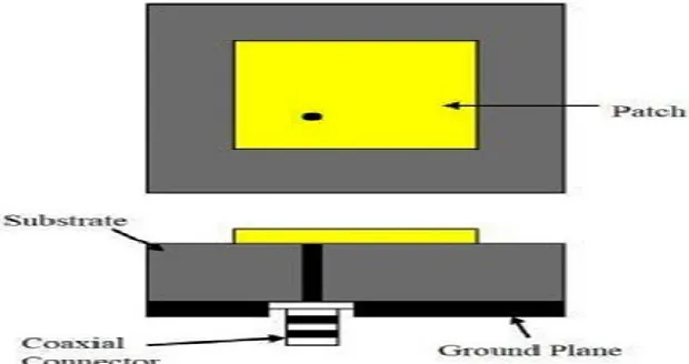
A. Coaxial Probe Feed
The Coaxial feed or probe feed is a very common technique used for feeding Microstrip patch antennas. The inner conductor of the coaxial connector extends through the dielectric and is soldered to the radiating patch, while the outer conductor is connected to the ground plane. The main advantage of this type of feeding scheme is that the feed can be placed at any desired location inside the patch in order to match with its input impedance.
However, its major drawback is that it provides narrow bandwidth and is difficult to model since a hole has to be drilled in the substrate and the connector protrudes outside the ground plane, thus not making it completely planar for thick substrates.
[image:3.612.150.460.552.716.2]A Probe Fed antenna consists of a microstrip patch fed by the center conductor of a coaxial. The outer coaxial conductor is electrically connected to the ground plane. Due to the absence of a microstrip feed line, the substrate thickness and permittivity can be designed to maximize antenna radiation.
However, the probe center conductor underneath the patch causes undesired distortion in the electric field between the patch and ground plane and produces undesired reactive loading effects at the antenna input port [1,2]. The undesired reactance can be compensated by adjusting the probe location on the patch.
III. DESIGN AND RESULTSOF ANTENNA
A. Design of Semicircular-Slotted Patch Antenna using Rectangular patch using Coaxial Probe feed:
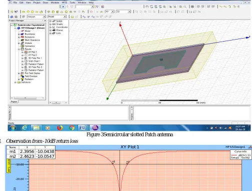
[image:4.612.47.551.227.608.2]In this design we introduce semicircular slot in patch to made rectangular antenna as according to reference paper and design a single band antenna.
[image:4.612.47.558.511.717.2]Figure 3Semicircular slotted Patch antenna B. Observation from -10dB return loss
Figure 4 Return loss graph of square patch antenna
2.00 2.20 2.40 2.60 2.80 3.00
Freq [GHz] -60.00
-50.00 -40.00 -30.00 -20.00 -10.00 0.00
d
B
(S
(1
,1
))
HFSSDesign1
XY Plot 1 ANSOFT
M
Y
1
:
-1
0
.0
0
0
0
MX1: 2.4283
m1 m2
-51.9404
Curve Info
dB(S(1,1)) Setup1 : Sw eep
Name X Y
m1 2.3956 -10.0438
m2 2.4623 -10.0547
Name Delta(Freq) Delta(X)
The Proposed antenna is resonating at 2.4 GHz frequency means provide a single band as described below: Resonant frequency = 2.4 GHz at -51.94 dB( S-parameter)
C. Observation from VSWR
[image:5.612.65.553.134.305.2]The proposed antenna give the value of VSWR is very close to ideal value one at resonating frequency which is practically best.
Figure 5 VSWR graph of square patch Antenna
VSWR at Resonant frequency 2.4 GHz is 1.0051
D. Smith Chart
The smith chart curve of Proposed Antenna is shown in Figure.
[image:5.612.53.569.383.579.2]Impedance Matching at maximum VSWR frequency (2.4 GHz) = 0.9975 ×50= 49.88 ohm
Figure 6 Smith chart curve of square patch antenna
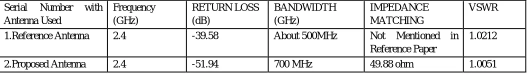
E. Conclusion between Reference Antenna and Proposed Antenna:
So the proposed antenna give the better result in terms of better S-Parameters, better VSWR and impedance matching.
Table 1 Difference Table between Reference and Proposed antenna Serial Number with
Antenna Used Frequency (GHz) RETURN LOSS (dB) BANDWIDTH (GHz) IMPEDANCE MATCHING VSWR
1.Reference Antenna 2.4 -39.58 About 500MHz Not Mentioned in Reference Paper
1.0212
2.Proposed Antenna 2.4 -51.94 700 MHz 49.88 ohm 1.0051
2.00 2.20 2.40 2.60 2.80 3.00
Freq [GHz] 0.00 10.00 20.00 30.00 40.00 50.00 60.00 70.00 80.00 V S W R (1 ) HFSSDesign1
XY Plot 2 ANSOFT
MX1: 2.4283 1.0051
Curv e Inf o VSWR(1) Setup1 : Sw eep
5.00 2.00 1.00 0.50 0.20 0.00 5.00 -5.00 2.00 -2.00 1.00 -1.00 0.50 -0.50 0.20 -0.20 0.00 0 10 20 30 40 50 60 70 80 90 100 110 120 130 140 150 160 170 180 -170 -160 -150 -140 -130 -120 -110
-100 -90 -80 -70
-60 -50 -40 -30 -20 -10 HFSSDesign1
Smith Chart 1 ANSOFT
m1
Curve Inf o S(1,1) Setup1 : Sw eep
Name Freq A ng Mag RX Q VSWR
[image:5.612.44.573.647.722.2]IV. CONCLUSION
In this thesis, a microstrip patch antennas for a single frequency 2.4 GHz (that cover ISM Band) with only coaxial probe feeding technique is presented. The various parameters like return loss, radiation pattern, smith chart, electric field and VSWR are plotted for each antenna.
The proposed antenna can be suitably employed for WLAN, Wi-Fi, Bluetooth communication applications. Results show very low loss, about ideal VSWR Value, good impedance matching and good radiation patterns in the operating band.
REFERENCES
[1] Ramesh Garg, PrakashBhartie, InderBahl, ApisakIttipiboon, “Microstrip Antenna DesignHandbook”, Artech House Inc. Norwood, MA, 2001, pp. 1-68, 253-316.
[2] Ahmed Fatthi Alsager , “Design and Analysis of Microstrip Patch Antenna Arrays”, M.Tech Thesis in Electrical Engineering– Communication and Signal processing 2011, University College of Boras School of Engineering, SE‐501 90.
[3] Macro A.Antoniades, and George V. Eleftheriades, “A Compact Multiband Monopole Antenna with a Defected Ground Plane,” IEEE, Antennas and Wireless Propagation Letters, Vol.7, 2011.
[4] Joseph Costan Tine1, Karim Y. Kabalan, Al EI-Hajj, Mohammad Rammal “New Multi-Band Microstrip Antenna Design For Wireless Communications” International Journal of Science, Engineering and Technology ,Vol. 49, No. 6,2011.
[5] Abdel Fattah Sheta, Ashraf S. Mohra, And Samir F. Mahmoud “Modified Compact H-Shaped Microstrip Antenna For Tuning Multi-Band Operation”, International Conference on Computational Intelligence and Computing Research., Vol. 9, No. 3,2011.
[6] L. M. Si And X. Lv, “CPW-Fed Multi-Band Omni-Directional Planar Microstrip Antenna Using Composite Metamaterial Resonators For Wireless Communications” International Conference on Computational Intelligence and Computing Research. Pier 83, 133–146, 2012.
[7] P.Mythili, Philip Cherian, S.Mridula, Binu Paul “Design Of A Compact Multiband Microstrip Antenna”, International Journal of Science, Engineering and Technology, vol 18, 2012.
[8] Pramendra Tilanthe, P. C. Sharma “Design Of A Single Layer Multiband Microstrip Square Ring Antenna”, International Conference on Computational Intelligence and Computing Research, vol 3, 2012.
[9] Nasser Ojaroudi, Mohammad Ojaroudi, Noradin Ghadimi, 2012. “Dual Band-Notched Small Monopole Antenna with Noval W-Shaped Conductor Backed-Plane and Novel T-Shaped slot for UWB Applications,” IET Microwave and Antenna Propagation, Vol. 7, Issue 1, pp. 8-14.
[10] Muhammad R. Khan, Mohamed M. Morsy, Muhammad Z. Khan and Frances J. Harackiewicz “Miniaturized Multiband Planar Antenna for GSM, UMTS, WLAN and Wimax Bands” International Journal of Advanced Technology in Engineering and Science , vol 22, Issue no.5,2013.
[11] Halappa R. Gajera, Anoop C.N, M. M. Naik. G, Archana S. P, Nandini R Pushpitha B.K, Ravi Kumar M.D, “The Microstrip Fed Rectangular Microstrip Patch Antenna(RMPA) with Defected Ground Plane for HIPERLAN/1” IJECT Vol. 2, Issue 3, Sept. 2013.
[12] Zuhura Juma Ali, “A Miniaturized Ultra Wideband (UWB) Antenna Design for Wireless Communications” International Journal of Scientific & Research Publications, Vol 4, Issue 7, July 2014.
[13] A. Gnandeep reddy, k. Gopivasanth kumar, “Design And Simulation Of A L And U‐Shaped Slot Compact Planar Monopole Antenna”, International Journal of Science, Engineering and Technology, 2014.
[14] Vasujadevi Midasala, Dr. P. Siddaiah, “Rectangular Patch Antenna Array Design at 13GHz frequency Using HFSS”, 2014 IEEE International Conference on Computational Intelligence and Computing Research.
[15] R.Bargavi,K.Sankar and S.Arivumani Samson, “Compact Triple band H-Shaped Slotted Circular Patch Antenna”, International Conference on Communication and Signal Processing, International Journal of Advanced Technology in Engineering and Science April 3-5, 2014, India
[16] Sumeet Singh Bhatia, Jagtar Singh Sivian, Manpreet Kaur, “Comparison of feeding techniques for the design of microstrip rectangular patch antenna for x-band applications”, International Journal of Advanced Technology in Engineering and Science, Volume No.03, Special Issue No. 02, 2015.
[17] Chandra Bhan, Ajay Kumar Dwivedi, Brijesh Mishra, Anil Kumar, “Quad Bands U-shaped Slot Loaded Probe Fed Microstrip Patch Antenna ”, IEEE, 2015 Second International Conference on Advances in Computing and Communication Engineering.
[18] Udit Raithatha, S. Sreenath Kashyap & D. Shivakrishna, May 2015, “Swastika Shaped Microstrip Patch Antenna for ISM Band Applications” international journal IRJET.
[19] Alejandro Borja, “Reconfigurable Microwave Circuit Based on a Single Triangular Microstrip Patch” 978-1-4799-7815-1/15/2015 IEEE, Page No. 2253, AP-S 2015.
[20] Gurpreet Kaur, Er. Sonia Goyal, “Effect of Height on Edge Tapered Rectangular Patch Antenna using Parasitic Stubs and Slots’’, International Journal of Engineering Trends and Technology (IJETT) – Volume 34 Number 8- April 2016.
[21] R.K. Sharan, S.K. Sharma, “ A .Gupta, R.K Chaudhary, An Edge Tapered Rectangular Patch Antenna with Parasitic Stubs and Slot for Wideband Applications, Wireless Pers Commun Vol 86, pp 1213–1220, 2016.
[22] M. Tarikul Islam, M. Samsuzzaman, M. Z. Mahmud, M.T. Islam, “A Compact Spectacles Shaped Patch Antenna for UWB Applications”, 9th International Conference on Electrical and Computer Engineering, IEEE, 20-22 December, 2016, Dhaka, Bangladesh.[Reference Paper]
[23] P.Surendra Kumar, B.Chandra Mohan, “Dual-Frequency Vertex-Fed Pentagonal Slot On Rectangular Patch For WLAN/WiMAX Applications”, 978-1-5090-3646/ 2016 IEEE.
[24] Ranjan Mishra, Raj Gaurav Mishra, Piyush Kuchhal, “Analytical Study on the Effect of Dimension and Position of Slot for the Designing of Ultra Wide Band (UWB) Microstrip Antenna”, Internaional Conference on Advances in Computing, Communications and Informatics (ICACCI), Sept. 21-24, 2016, Jaipur, India, 978-1-5090-2029-4/16/IEEE.
[26] Amit A. Deshmukh, Priyal Zaveri, Sanjay Deshmukhand Anuja Odhekar, “Analysis of Circularly Polarized E-shaped Microstrip Antenna”, IEEE 2016 International Symposium on Antennas and Propagation (APSYM).
[27] B. Zoubiri, A. Mayouf, F. Mayouf, S. Abdelkebir and T. Devers, “Rectangular Microstrip Antenna Gain Enhancement Using Elliptical EBG Structure”, IEEE 2016 7th International Conference on Sciences of Electronics, Technologies of Information and Telecommunications (SETIT)
[28] R. Kiruthika T. Shanmuganantham Rupak Kumar Gupta A Novel Dual Band Microstrip Patch Antenna with DGS for X-band Applications IEEE International Conference on Computer, Communication, and Signal Processing (ICCCSP-2017)
[29] Mohamed Tarbouchand Abdelkebir El Amri, “Compact CPW-Fed Microstrip Octagonal patch antenna with H slot for WLAN and WIMAX Applications”, 5090-6681-0/17/2017 IEEE
[30] T.Shanmuganatham, “Design of Multi Utility Multi Band Microstrip Calculator Shaped Patch Antenna Using Coaxial Feed”, IEEE International Conference on Computer, Communication, and Signal Processing (ICCCSP-2017)
[31] T.Shanmuganatham and Deepansu Kaushal “Dual Band Microstrip Caution Patch Antenna for Space Applications”, IEEE International Conference on Computer, Communication, and Signal Processing (ICCCSP-2017)
[32] Anamika Banwari, “Low loss semicircular slotted microstrip patch antenna for ISM band applications”, International Conference on Computer, Communications and Electronics, July 01-02, 2017