6
I
January 2018
Performance Analysis of Permanent Magnet
Synchronous Generator Wind Turbine for Variable
Wind Velocity
Deepak Bohra1, M. K. Bhaskar2, Dharmendra Jain3, Manoj Chouhan4, Vishvendra Prasad Goyal5
1, 2, 3, 4
Dept. of Electrical, M.B.M. Engineering College, JNV University, Jodhpur, Rajasthan, India 5
Dept. Of Electronics, Dehradun Institute of Technology, Dehradun.
Abstract: The interest in wind energy system is growing worldwide to reduce dependency on fossil fuel and to minimize the adverse impact of climate change. Currently, doubly fed induction generator (DFIG) based variable speed wind turbine technology with gearbox is dominating the world market share. However, the problems associated with induction generator based wind turbines are reactive power consumption, mechanical stress and poor power quality. Moreover, the gearbox requires regular maintenance as it suffers from faults and malfunctions. Therefore, it is important to adopt technologies that can enhance efficiency, reliability and reduce system cost of wind based power generation system. The performance of a variable speed wind turbine can be enhanced significantly by using a low speed permanent magnet synchronous generator (PMSG) without a gearbox. The main features of PMSG based wind turbines are; gearless operation, higher efficiency, enhanced reliability, smaller size, reduced cost and low losses.
Keywords: Wind Energy, Wind Velocity, pitch angle, Cut-in Speed, Cut-out Speed, Wind Turbine, PMSGWT-Modal, WECS, MATLAB/SIMULIK.
I. INTRODUCTION
Wind energy is available and clean source of energy that has been used to generate electrical power. The focus on electrical power generated from wind energy has been increased due to the environmental problems that fossil fuels make. Global warming and green house emissions are the main harmful results of fossil fuel consumption. The first wind turbines appeared at the beginning of the last century and technology was improved step by step from the early 1970s. By the end of the 1990s, wind energy has re-emerged as one of the most important sustainable energy resources. Currently, five countries (Germany, USA, Denmark, India and Spain) concentrate more than 83% of worldwide wind energy capacity in their countries. The wind farms are located on land and due to scarcity of land and wind energy extraction wind turbine site are located offshore. The electrical wind turbine generators are an interface connection between the mechanical part of the system and the electrical part. The main function of the electrical generator is to convert the mechanical energy coming from the wind turbine which acts as a prime mover to electrical energy that is transferred to the electrical grid. Wind turbines are different types and generally categorized in two types according the wind speed, variable wind speed turbines and fixed wind speed turbines.
Wind turbines electrical generators commonly used are:
II. WINDTURBINEOUTPUTEQUATION
The actual power output of a wind turbine generator (WTG) system depends on the actual wind speed, rated wind speed, cut in speed (i.e., speed at which system losses equal the extracted wind power) and cut out speed (i.e. speed at which the wind mill has to be shut down for safety reasons.) The power output can be approximated by the relation [4].
Actual power output = 0 for 0 < ν < ν ci
= (A + Bν +cν2) pr for ν ci <ν < ν r ...……..1 = Prfor ν r<ν <ν co
= 0 for V >Vco
Where ν = actual wind speed
Pr = rated power output
νci= cut in wind speed
νr = rated wind speed
νco = cutout wind speed A, B, C are functions of νciand νr
[image:3.612.136.478.270.493.2]Fig. 1 shows three circular at inlet, turbine blade and exit of wind
Fig.1: Energy Extraction by Wind Turbine Rotor [5]
Let Ai = area at inlet, m2 At = area at turbine rotor, m2 Ae = area at exit, m2
νi = wind velocity at inlet, m/s νt = wind velocity at turbine rotor, m/s νe = wind pressure at exit,m/s
pi = wind pressure at inlet, N/m2 pe = wind pressure at exit, N/m2
pt+ = wind pressure at rotor upstream, N/m2 Pt- = wind pressure at rotor downstream, N/m2 ρ = density of air, kg/m3
The mass flow rate must be the same across the three areas i.e. inlet, turbine rotor and exit. Therefore
ρ Ai νi= ρ At νt= ρ Ae νe ……….2 The rotor induces a velocity variation which is superimposed on the free stream velocity. The induced flow at rotor is – a νi where ‘a’ is called the axial flow induction factor. Therefore
The air undergoes a change in velocity νi –νe from inlet to exit. The rate of change of momentum is equal to mass flow rate multiplied by change of velocity. Therefore
Rate of change of momentum = (νi – νe) ρAtνt ………4 The force which causes change of momentum is due to pressure difference across the rotor. The change in pressure is form pt+, to pt -,. Therefore
( pt+ - pt-) At = (i - e) Ati = (i - e) Ati (1-a) ………5 To find (pt+- pt-) we can use Bernaulli’s equation. As per Bernaulli’s equation, under state conditions the total energy in the flow (i.e. sum of kinetic energy, static pressure energy and gravitational potential energy) remains constant provided no work is done on or by the fluid. Thus for a unit volume of air
2
1
2 + p + gh= constant ………6
Upstream conditions give
2
1
ii2 + pi + pighi=
2
1
tt2 + pt+ + tght ………….7
Assuming the flow to be incompressible (i = t) and horizontal (hi = ht) we get
2
1
i2+ pi=
2
1
t2+ pt+ …………8
Downstream conditions give
2
1
e2 + pi=
2
1
t2 + pt ………..9
Subtracting Eq. (9) from Eq. (8)
pt+ -pt- =
2
1
(i2 - e2) ………10
Subtracting Eq. (10) into Eq. (5) we get
2
1
(i2-e2) At = (i-e) Ati (1-a) ………..11
Eq. (11) gives
e = (1-2a) i ………..12 Thus half of axial speed loss occurs upstream of rotor and half downstream. From Eq. (5) the force F on air is
F= (pt+ - pt-) At= 2Ati2a(1-a) ……….13 The rate of work done by force F is F t. The power extracted from air is Pt and is given by
Pt = Ft= 2Ati3a(1-a)2 ………14 Power coefficient Cp is defined as
t i t p
A
P
C
32
1
………15In Eq. (15),
2
1
iAt represents power available in air.
Combining eq. (14) and (15)
Cp = 4a(1-a)2 ………16
For maximum value of
da
dC
C
p,
p should be zero.0
4
16
12
2
a
a
da
dC
por 3a2 – 4a + 1 = 0
Which gives
3
1
a
……….17Therefore
0
.
593
27
16
3
1
1
3
1
4
max .
pC
……….18This means that an ideal turbine cannot extract more than 59.3% of power in the undisturbed wind. This is known as Betz Criterion (named after German aerodynamicist Albert Betz)
= Density of air = 1.293 kg/m3
2
4
D
A
t
= where D is diameter of rotorSince t = vi (1-a) and
3
1
a
i t
3
2
3
)
2
1
(
i i ea
Though the power coefficient for an ideal with turbine is 0.593, it has been found that its more practical value is about 0.45. Further the generator also has some losses and the overall power coefficient is about 0.35 [5].
III.WINDTURBINEPOWERCHARACTERISTICS
The power curve is the most important technical information for a wind turbine. The power characteristics of a wind turbine are defined by the power curve and the power curve relates the mechanical power of the turbine vs. wind speed. The power curve is a wind turbines certificate of performance that is guaranteed by the manufacturer. A typical power curve is shown in Fig.2. This curve is characterized by three speeds:
A. Cut-in speed B. Rated wind speed C. Cut out wind speed
The cut in wind speed is the speed at which wind turbine starts to operate and deliver power. Below cut-in wind speed the turbine does not capture enough power to compensate for the power losses in the wind turbine drive train. Therefore, the wind turbine is shut down. The rated wind speed is the speed at which the wind turbine produce rated power. The cut-out speed is the highest wind speed at which the turbine is allowed to operate before it shut down. The turbine must be shut down to prevent mechanical damage if the wind speed is above the cut-out speed.
Fig.2: Wind Turbine Power Curve in Different Operating Region [6]
IV.DISCRETEWINDHISTOGRAM
Working with the mathematics of probability and statistics, which may be new territory for some. To help motivate our introduction to this material, we will begin with some simple concepts involving discrete functions involving wind speeds, and then we can move on to more generalized continuous functions.
What do we mean by the average of some quantity? Suppose, for example, we collect some wind data at a site and then want to know how to figure out the average wind speed during the measurement time. The average wind speed can be thought of as the total meters, kilometres, or miles of wind that have blown past the site, divided by the total time that it took to do so [7].
Table-I: Wind data for a year [7]
Wind Speed (m/s) Time (Hrs/yr) Wind Speed (m/s) Time (Hrs/yr)
0 24 13 243
1 276 14 170
2 527 15 114
3 729 16 74
4 869 17 46
5 941 18 28
6 946 19 16
7 896 20 9
8 805 21 5
9 690 22 3
10 568 23 1
11 444 24 1
12 335 25 0
Fig. 3: wind histogram showing hours that the wind blows at each wind peed [7].
V. PMSGBASEDGEARLESSDIRECTDRIVEVARIABLESPEEDWINDTURBINETECHNOLOGY
In this configuration, the generator rotor is directly connected to the turbine rotor without any gearbox and the generator is interfaced with the grid/load using full scale AC-DC-AC power converters as shown in Fig.4. This configuration is most suited for full power control as it is connected to the grid through a power converter. The permanent magnet synchronous generators (PMSGs) used in this configuration are low speed generators with suitable number of poles and able to produce higher torque at low speed. The full-scale power converter can perform smooth grid connection over the entire speed range. The power electronic converters used in this configuration have two primary goals: to act as an energy buffer (DC-link) for the power fluctuations caused by the wind turbine and for the transients coming from the grid side and enables the system to control active and reactive power. The main features of PMSG based wind turbines are -
1) Gearless operation and enhanced reliability. 2) Simple structure, smaller size and reduced cost. 3) Low mechanical and electrical losses.
4) Higher power factor and efficiency. 5) No requirement for reactive power support. 6) Higher cost and power losses in the converters. 7) No need of external excitation.
This type of wind turbine has a better fault ride through capability compared with the DFIG system with better efficiency and lesser complexity. Therefore, direct drive variable speed wind turbine is becoming more attractive. However, the reactive power requirements can be fulfilled through the power converter control for both DFIG and direct drive wind turbine with full scale converter concepts [6].
[image:7.612.106.511.544.723.2]VI.MODELLINGOFTHEPMSGWINDTURBINE
The Permanent Magnet Synchronous Generator (PMSG) offers better performance than other generators because of its higher efficiency and of less maintenance since they don’t have rotor current and can be used without a gearbox, which also implies a reduction of the weight of the nacelle and a reduction of costs. VSWT wind turbine generator consists of another three parts: wind speed, wind turbine and drive train.
Fig. 5 shows a three phase two poles PMSG. It has 3 phase Y-connected stator windings and a permanent magnet in the rotor. The stator windings are identical windings displaced 1200, each with a turns number of Ns and resistance Rs. For our analysis we assume that the stator windings are sinusoidal distributed. Damper windings are neglected because the permanent magnet is a poor electrical conductor and the eddy current that flow in the nonmagnetic materials securing the magnets are small. Hence large armature current can be tolerated without significant demagnetization [6].
The stator of a PM synchronous generator is similar to the wound rotor synchronous generator and the back emf produced by the permanent magnets is the same as that produced by an excited coil. In developing mathematical model for a PMSG we will assume the following;
A. The stator windings are sinusoidal distributed along the air gap B. Magnetic saturation is negligible
C. The back emf is sinusoidal.
[image:8.612.178.456.314.472.2]D. The variation of phase inductance is sinusoidal
Fig.5: Three Phases, Two Pole PMSG [6]
VII. SIMULATIONOFPMSGWINDTURBINE
The system analysed is a variable speed wind turbine based on a multi-pole PMSG. Due to the low generator speed, the rotor shaft is coupled directly to the generator, which means that no gearbox is needed.
The generator is connected to the grid via an AC/DC/AC converter, which consists of an uncontrolled diode rectifier, boost chopper circuit and a PWM voltage-source inverter. For this topology of converter, operation at relatively low wind speeds is possible due to the inclusion of the boost circuit. The boost circuit can maintain the DC bus link voltage at a constant value. A transformer is located between the inverter and the Point of Common Connection (PCC) in order to raise the voltage by avoiding losses in the transport of the current. It must be noted that this study is dedicated to analyse and implement the model from the wind turbine to the PMSG. For this reason, transformer, grid, rectifier and inverter models and their controls will not be considered [6].The final model of PMSG wind turbine takes wind speed and pitch angle as input parameter and gives the rotor speed, torque, output current, output voltage and output active and reactive power.
VIII. SIMULATIONRESULTSFORPMSGWINDTURBINE-MODEL(PMSGWT-MODEL)
Find the value of power when different wind speed and fixed pitch angle. From Simulation find the value of Max. Power, Min. power, Current, voltage, torque and rotor speed. But in this paper mainly focus on Max. Power (Active Power). Simulation results are taken on same parameters of the PMSGWT-Model.
Fixed parameters = pitch angle in degree, Variable parameter = Wind speed in meter per second (m/s). The value of power for permanent magnet synchronous generator wind turbine model (PMSGWT-Model) is shown in Table-II.
Table-II: Simulation Results of Generated Power (P) in Watts for PMSGWT-Model
Wind Speed
P at Pitch angle =0
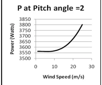
P at Pitch angle =2
P at Pitch angle =4
P at Pitch angle =6
P at Pitch angle =8
P at Pitch angle=10
P at Pitch angle=12
(1) (2) (3) (4) (5) (6) (7) (8)
1 3564 3563 3563 3563 3563 3563 3563
2 3563 3563 3563 3563 3563 3563 3563
3 3564 3562 3562 3562 3562 3563 3563
4 3565 3562 3562 3562 3562 3562 3562
5 3568 3561 3561 3561 3562 3562 3563
6 3573 3561 3561 3562 3562 3563 3564
7 3580 3561 3561 3562 3564 3565 3566
8 3591 3562 3562 3564 3566 3568 3570
9 3604 3564 3564 3566 3569 3572 3574
10 3622 3567 3567 3570 3574 3577 3581
11 3644 3571 3571 3575 3580 3585 3590
12 3670 3576 3576 3481 3588 3594 3601
13 3701 3583 3582 3589 3597 3605 3614
14 3738 3590 3590 3599 3609 3619 3629
15 3780 3600 3600 3611 3623 3635 3647
16 3827 3611 3611 3624 3639 3653 3668
17 3882 3624 3624 3640 3657 3675 3692
18 3943 3639 3639 3658 3678 3699 3720
19 4011 3656 3656 3678 3701 3726 3750
20 4086 3675 3675 3700 3728 3756 3784
21 4169 3696 3696 3725 3757 3789 3822
22 4259 3719 3719 3753 3789 3826 3863
23 4357 3745 3745 3783 3824 3866 3909
24 4464 3773 3773 3816 3863 3910 3958
25 4579 3803 3803 3852 3904 3958 4012
The simulation results for PMSGWT model as shown in the Table-II. These results are achieved by different operating condition of PMSGWT model. To achieve the results as shown in the colomn-2 by measuring the generated power by keeping pitch angle zero-degree as a fixed parameter and vary the wind speed from 1 m/s to 25 m/s, in steps 1 m/s as an increment. The maximum power 4579 Watts is achieved at fixed pitch angle zero-degree, wind speed is 25 m/s. Similarly to achieve the results as shown in the colomn-3 by measuring the generated power by keeping pitch angle two-degree as a fixed parameter and vary the wind speed from 1 m/s to 25 m/s, in steps 1 m/s as an increment. The maximum power 3803 Watts is achieved at fixed pitch angle two-degree, wind speed is 25 m/s. Now to achieve the results as shown in the colomn-3 to 8 by varying pitch angle and wind speed.
IX.GRAPHICALLYREPRESENTATIONOFPMSGWT-MODELRESULT
[image:10.612.109.287.81.218.2]
Fig. 6: Power v/s Wind Speed Curve Fig. 7: Power v/s Wind Speed Curve
Fig. 8: Power v/s Wind Speed Curve Fig. 9: Power v/s Wind Speed Curve
[image:10.612.96.264.433.626.2]
Fig. 10: Power v/s Wind Speed Curve Fig. 11: Power v/s Wind Speed Curve
X. CONCLUSION
[image:10.612.364.524.436.626.2]REFERENCES
[1] Kuldipsinh. I. Rathod, Mahipalsinh.B.Jhala & A.D.Patel, “ Modeling and Simulation of Wind Turbine Connected to Pmsg for Wind Mill Application”,
International Global Journal For Research Analysis, Volume: 3 | Issue: 3 | March 2014.
[2] Prerna Badoni, S. Bhanu Prakash, “Modeling and Simulation of 2 MW PMSG Wind Energy Conversion Systems”, IOSR Journal of Electrical and Electronics
Engineering (IOSR-JEEE), e-ISSN: 2278-1676,p-ISSN: 2320-3331, Volume 9, Issue 4 Ver. I, Jul – Aug. 2014.
[3] S. Samanvorakij & P. Kumkratug, “Modelling and Simulation PMSG based on Wind Energy Conversion System in MATLAB/SIMULINK”, Proc. of the
Second Intl. Conf. on Advances in Electronics and Electrical Engineering — AEEE 2013.
[4] Deepak Bohra, M.K.Bhaskar, Dharmendra Jain, Manish Parihar, “Modelling and Simulation of Asynchronous Generator Wind Turbine for Different Wind
Speed”, International Journal of Emerging Technology and Advanced Engineering, ISSN 2250-2459, ISO 9001:2008 Certified Journal, Volume 7, Issue 10,
October 2017.
[5] B.R.Gupta, “Generation of Electrical Power”, S. Chand, 2009.
[6] Mujaddid Morshed Chowdhur, “Modelling and Control of Direct Drive Variable Speed Wind Turbine with Interior Permanent Magnet Synchronous
Generator”, PhD Thesis, University of Tasmania, June 2014.
[7] Gilbert M. Masters, “Renewable and efficient electric power systems”, Stand ford University, A John Wiley & sons, INC., Publication, New Jersey, 2004.
[8] Jasmin Martinez, “Modelling and Control of Wind Turbines”, Department of Chemical Engineering and Chemical Technology, Imperial College, London,
September 21, 2007.
[9] Phlearn Jansuya and Yuttana Kumsuwan, “Design of MATLAB/Simulink Modeling of Fixed-Pitch Angle Wind Turbine Simulator”, Sciversa Science Direct,
Energy Procedia , August, 2013.
[10] Prerna Badoni, S. Bhanu Prakash, “Modeling and Simulation of 2 MW PMSG Wind Energy Conversion Systems”, IOSR Journal of Electrical and Electronics
![Fig.1: Energy Extraction by Wind Turbine Rotor [5]](https://thumb-us.123doks.com/thumbv2/123dok_us/8296896.853154/3.612.136.478.270.493/fig-energy-extraction-wind-turbine-rotor.webp)
![Fig. 3: wind histogram showing hours that the wind blows at each wind peed [7].](https://thumb-us.123doks.com/thumbv2/123dok_us/8296896.853154/7.612.106.511.544.723/fig-wind-histogram-showing-hours-wind-blows-wind.webp)
![Fig.5: Three Phases, Two Pole PMSG [6]](https://thumb-us.123doks.com/thumbv2/123dok_us/8296896.853154/8.612.178.456.314.472/fig-three-phases-two-pole-pmsg.webp)