REER Leach Based Protocol in WSN
Noopur #1, Dr,Puneet Gosawami*2
Research Scholars, Associate Professor2nd Department of Computer science & Engineering Galaxy Global Imperial Technical Campus, Ambala
Haryana, India
Abstract- . Wireless sensor network have become an active area for researchers now a days. A sensor node carry small amount of resources in terms of processor, battery power, memory and communication range, but when a great number of sensor nodes work together they are able to complete a good volume of task. It is just because of Wireless Sensor Network we are able to interact with physical world directly. Compared with the traditional wireless networks, wireless sensor networks have energy constraint, low-data-rate of high outmoded and data flow of high-to-one, and so on. . Better data aggregation technique may reduce the overall energy dissipation for a cluster in LEACH as battery consumption is important fact to be taken in to consideration which is a scarce resource and can’t replace further in the network after battery loss. Reliabilityis also a major necessity in data aggregation. A novel smart re-clustered reliable energy efficient routing (SRREER) protocol is a protocol based on optimal data aggregation technique which helps to reduce the energy dissipation and reducing delay in terms of data delivery to BS.
Keywords: WSN, Layered Leach ,Cluster, REER
I. INTRODUCTION
Each sensor node consists of sensing, processing, communication and power subsystem. Sensing subsystem is used to sense the phenomena, processing subsystem is used to process that sensed information as an output from sensor subsystem, communication subsystem is used to move data along the nodes from source to sink and the power subsystem is used to provide energy to sensor nodes for monitoring the location at low cost and low time. Battery is such an example in case of power subsystem.
Fig1 . Basic components of WSN
Basic Types of Wireless Sensor Network Architecture
The two basic type of sensor network architecture are layered and cluster.
Fig 1.1: Layered Architecture
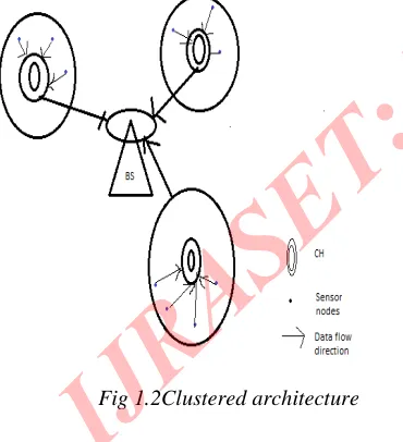
[image:3.612.73.258.398.601.2]1.2Clustered architecture: In this architecture multiple no of clusters exists which are formed by Sensor nodes. And a cluster head exists in between each cluster. If these nodes want to exchange their message they have to report to cluster head for that. And these cluster heads then sends messages to BS. Clustered architecture provides the inherent suitability of data fusion because the data gathered by all members of cluster which are nosed here is fused at the cluster head, and then the resulting information needs to be communicated to the BS. Cluster formation and election of each cluster head must be an independent, distributed process
Fig 1.2Clustered architecture
The remainder of the paper is organized as follows. Section 2 describes Leach Protocol done so far in this field. Section 3 describes Leach Based Routing Protocol. Finally the paper concludes with a summary.
LEACH was proposed by Heinzelman, Chandrakasan and Balakrishnan. It is a hierarchical cluster based routing protocol for wireless sensor networks. This protocol partitions the nodes in to clusters. LEACH randomly selects nodes as cluster-heads (CH) and performs periodic reelection. Cluster Head (CH) is responsible for creating and manipulating a TDMA (Time division multiple access) schedule and sending aggregated data from nodes to the BS where these data is needed using CDMA (Code division multiple access). And the remaining nodes are cluster member. The operation of leach protocol is crack into two phases: set up and steady.
Fig 2.1 Architecture of leach
3. RELATED WORK
Muhamnmad Omer Farooq et al [1] presents a multi-hop routing with low energy adaptive clustering hierarchy protocol.MR-LEACH follows the fundamental principle of multi-hop routing from cluster-heads to a Base station to conserve energy, unlike the leach protocol. In MR-leach they partition the network into different layers of clusters. Where Cluster heads in each layer collaborates with the adjacent
layers to Transmit sensor’s data to the base station. Ordinary
nodes Join cluster heads based on the received signal strength indicator (RSSI). The transmission of nodes is controlled by a base station (BS) that defines the time division multiple accesses (TDMA) Schedule for each cluster-head. BS choses the upper layers cluster Heads to act as super cluster heads for lower layer cluster heads. By calculating performance evaluation it is shown that MR-LEACH achieves significant improvement in the leach protocol and provides energy efficient routing for WSN.
paper behaviors better performance than LEACH in the following three manners, the numbers of life nodes, energy consumption and data transmission.
JiaXu et al [3] propose a revised cluster routing algorithm named E-LEACH to enhance the hierarchical routing protocol LEACH. E-LEACH algorithm shows that, the original way of the selection of the cluster heads is random and the round time for the selection is fixed. In the E-LEACH algorithm, here consider the remnant power of the sensor nodes in order to balance network loads and changes the round time depends on the optimal cluster size. Outcome of simulation results show that our proposed protocol increases network lifetime at least by 40% when compared with the LEACH algorithm.
Energy-Efficient Clustering with One Time Setup for Wireless Sensor Networks
Heewook Shin et al [4] in the paper “Energy-Efficient Clustering with One Time Setup for Wireless Sensor Networks” proposed a new energy efficient clustering scheme. He stated that in LEACH, though, extra energy and time are consumed to reform clusters at the setup phase of every round. This side effect is bad as the number of clusters increases. This paper present a novel energy-efficient clustering scheme to remove cluster recreating process required at every round after the first round, which is called COTS (Clustering with One Time Setup). The proposed COTS allow that the role of cluster head is rotated among members in a cluster without cluster reforming process. This way significantly saves the energy because the cluster reforming process is not needed, resulting in increased network lifespan.
4.PURPOSED WORK
Re-clustered energy efficient routing protocol for WSN: The proposed model
Smart re-clustered reliable energy efficient routing protocol REER is deploy upon energy efficient and reliable data aggregation technique which overcomes the drawbacks of LEACH on the following facts:
There is requirement for operating energy resources for a long period of time. REER provides this feature
For scheduling of proper transmission of sensor nodes need of efficient energy is required. Improper transmission may cause to overhearing and idle listening causing energy loss. REER provides reliable transmission.
Reliable data transport is required for event detection in terms of when the packets are transmitted from the sensor nodes to sink and then to its neighbor nodes. REER provides this facility over LEACH.
By aggregating data there is increased amount of data collected in a single message which needs the alteration in reliability. SEERR provides this feature.
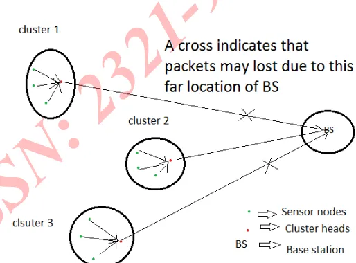
All the features discussed above overpower SEERR over the basic LEACH protocol. In LEACH, a small number of clusters are formed in self-organized manner. Data of each cluster is send to its own cluster head and then to base stations directly how far the base station is situated. And the problem arises due to this far location of base station because packets may be lost in between the path. And moreover measuring loss ratio at the base station or sink causes high delay. Fig. shows that data loss in LEACH.
Fig 4.1 Data loss in packet forwarding of data from each
cluster head to BS in LEACH
Here in fig we can see that BS is located miles away from clusters or source nodes and after aggregation of data at cluster head when they transmit their data along this far distance then data may be however lost or corrupted. Another major drawback is calculating loss ratio at BS is itself time or energy consuming. While REER perform loss ratio calculations at an intermediate node in between each cluster head and BS. This intermediate node called as smart node performs the calculations of loss ratio of each cluster which is the ratio of how many packets dropped and total number of packets broadcast from the source. Taken this loss ratio in consideration, the cluster size can be changed and forward node count of each node can be increased or decreased which is explained further.
[image:4.612.299.556.264.454.2]The operation of REER is broken upon in to some steps, where initial step is cluster building stage, after building of clusters second step is election of cluster head based on cost value calculations which is calculated by some random node chosen as supervisor node outside the cluster followed by third step which is data transmission phase in which data is transmitted from that supervisor node to the base station and alteration of cluster is done based on packet loss ratio calculated by supervisor node itself. In order to minimize overhead, the data transmission and cluster size alteration phase is long compared to the cluster building phase.
Data loss ratio calculation
We are considering the forward node count for each node which defines the broadcast and rebroadcast probability of a node. Forward node count is denoted by FNC.
Initially FNC [Nk] = FNC min, for all the nodes Nk, k=1,2…..
FNC (min) is defined as the minimum number of forwarding nodes. Without any loss of packet in general case we can consider that
FNC (min) =1, steps involved in Adaptive energy efficient forwarding phase are described below:
If N wants to forward the data collected to the BS, it adds its cost to the data packet and then broadcast the data packet to the closest neighbors.
When neighbor N1 gets the packet from N. it first determines whether its cost is low than that of N. in case of less cost, it further send out or forward the packet. Otherwise if N1 is not in the way of BS, it drops the packet.
Destination D calculates the loss ratio (LR) when packets reach to it. Loss ratio is defined as ratio of total packets broadcast and total packets dropped from the source.
D gives back this value of LR as a feedback to the Source node N.
After receiving LR by source node N, it analyzes this value of LR. It then changes the value of FNC as
FNC=FNC+ α, if LR> LR max……. (b)
Where we are taking α as min. decrement of the increment count and LR max is defined as the max threshold value of LR.
Then after modifying FNC it rebroadcast the data packets. When the rebroadcast packets receives by the destination D, it again find out the LR and gives back to N. It then reassigns the value of FNC.
For LR< LR max, then
FNC=FNC- α, until FNC>=FNC
min………(c)
This method of data aggregation is efficient in terms of reliability and energy since,
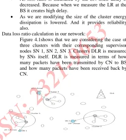
As loss ratio is measured by the SN itself delay is decreased. Because when we measure the LR at the BS it creates high delay.
As we are modifying the size of the cluster energy dissipation is lowered. And it provides reliability also.
Data loss ratio calculation in our network:
Figure 4.1shows that we are considering the case of three clusters with their corresponding supervisor nodes SN 1, SN 2, SN 3. Clusters DLR is measured by SNs itself. DLR is measured in terms of how many packets have been transmitted by CN to BS and how many packets have been received back by CN.
Fig. 4.2 loss ratio calculation for clusters
Initialization of network
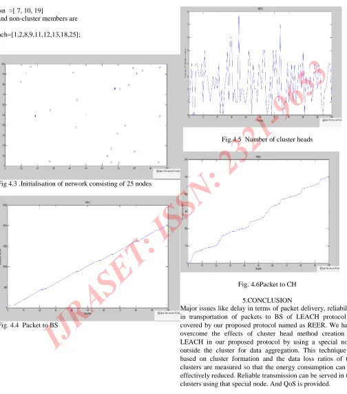
We have consider a network of 25 nodes where nodes dimensions for node 1 to 25 are
Node=[10,30;25,25;20,20;30,40;40,25;30,10;30,5;50,25;50,5; 60,20;70,10;70,45;95,40;80,25;72,15;80,15;90,20;15,70;40,80 ;50,70;40,60;55,55;60,75;65,60;70,80];
These nodes are considered in the network area of xm=100;
Ym=100;
Where the dimensions of sink is xd=99;
And yd=99.
Out of this network area; three non-overlapping regions for cluster is determined where sensor nodes are fitted. Three clusters are ch1, ch2 and ch3. These clusters have their members fitted in their own region.
Cluster member of first cluster is ch1= 3, 4, 5, 6
Respectively for ch2 and ch3 are
[image:5.612.295.550.141.424.2]sn =[ 7, 10, 19]
and non-cluster members are
nch=[1,2,8,9,11,12,13,18,25];
Fig 4.3 .Initialisation of network consisting of 25 nodes
[image:6.612.37.541.100.671.2]Fig. 4.4 Packet to BS
Fig.4.5 Number of cluster heads
Fig. 4.6Packet to CH
5.CONCLUSION
REFERENCES
[1] Muhamnmad Omer Farooq, Abdul BasitDogar, Ghalib Asadullah Shah, “MR-LEACH: Multi-hop Routing with Low
Energy Adaptive Clustering Hierarchy”2010 Fourth
International Conference on Sensor Technologies and Applications IEEE.
[2]Yuling Li, Luwei Ding, FengLiu, “The Improvement of
LEACH Protocol in WSN”, 2011International Conference on
Computer Science and Network Technology IEEE.
[3] JiaXu, Ning Jin, XizhongLou ,TingPeng, QianZhou,Yanmin Chen, “Improvement of LEACH protocol for WSN”, IEEE2012.
[4] Heewook Shin, SangmanMoh, and Ilyong Chung, “ Energy-Efficient Clustering with One Time Setup for Wireless Sensor
Networks”IEEE 2012.
[5] Shangwei Duan and Xiaobu Yuan, “Exploring Hierarchy Architecture for Wireless Sensor Networks Management” IEEE 2006.
[6] Qing Bian, Yan Zhang, Yanjuan Zhao, “Research on Clustering Routing Algorithms in Wireless Sensor
Networks”2010 International Conference on Intelligent
Computation Technology and Automation IEEE.
[7] M.Ismail and **M.Y.Sanavullah, “Security Topology In Wireless Sensor Networks With Routing Optimisation”, IEEE 2008.
[8] K. Romer and F. Mattern, “The design space of wireless sensor networks,” Wireless Communications, IEEE, Dec. 2004.
[9] Approving Renold, R.Poongothai, R.Parthasarathy,
“Performance Analysis of LEACH with Gray Hole Attack in Wireless Sensor Networks”, IEEE 2012.
[10] Rajiv Kr Tripathi ,Grad.Student MIEEE, Yatindra Nath